Work on the beleaguered U.S.S. BROWN C. STENNIS has been continuing at a rapid pace! For what really is the first time with one of my projects, I called for extensive backup from friends willing to lend some elbow grease. First, because some of them are more “car people” than me, and second, because everything on this thing is heavy. It’s like the Chevy of trucks: cheap and heavy.
Wait…. Hang on.
This post recaps all the events of about 2 weeks ago following its return from my mechanic; I elected to take it back since it had not yet been consistently diagnosable (i.e. it was becoming a “throw parts at it” situation) and I didn’t want to keep running up labor charges. I ended up going through a series of cross-checks and inspections and discovered the problem was all too familiar, but obfuscated by a compounding issue. In the end, it was literally entirely my fault, so I’m very satisfied; unlike most people, I’m only happy if I caused the entire mess in the first place.
Let’s begin.
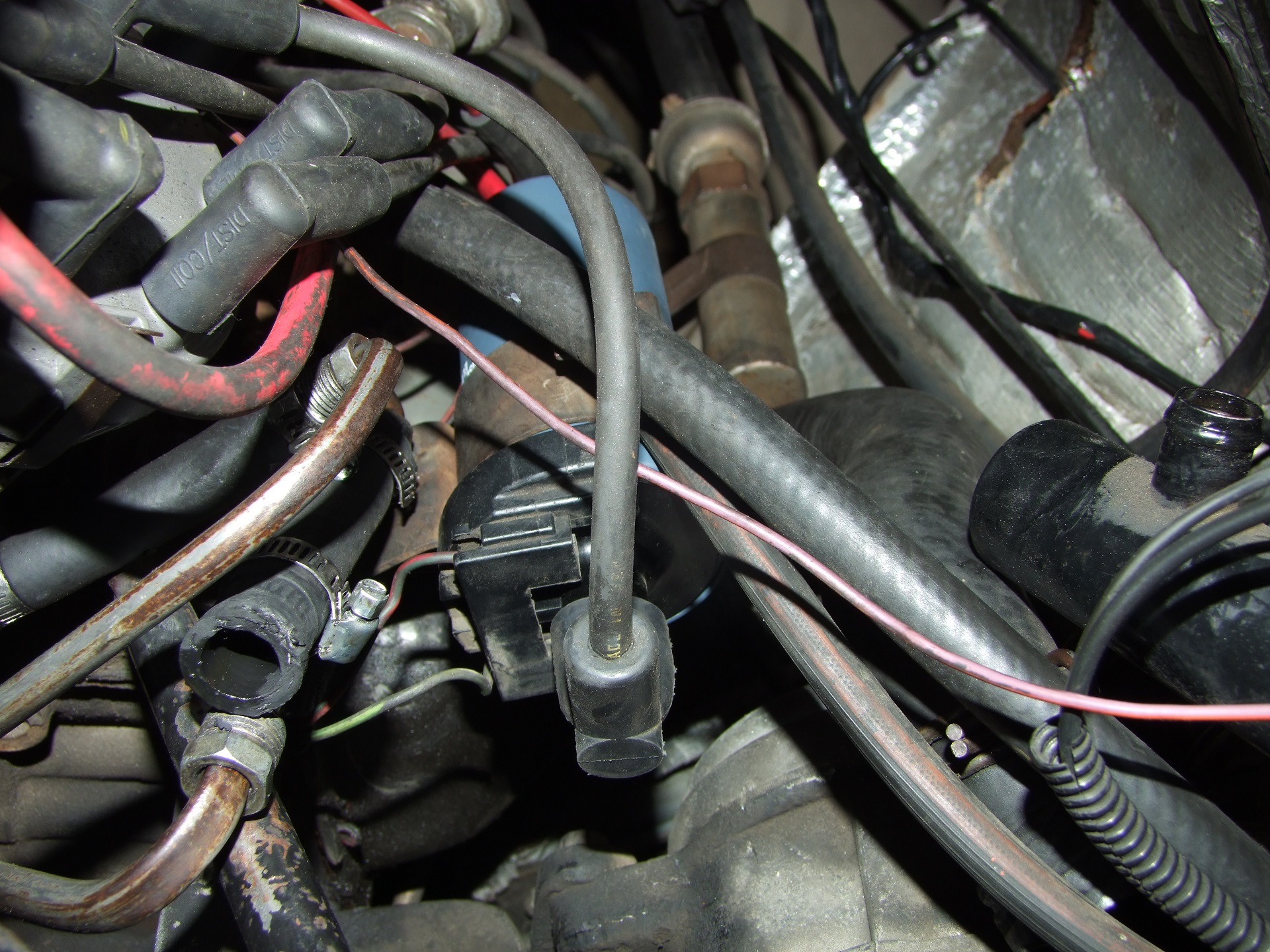
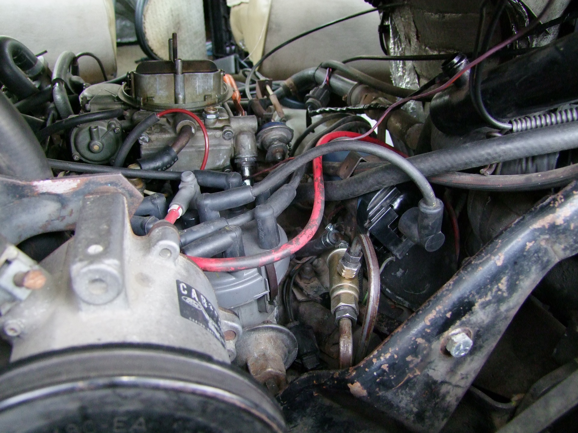
Prodding Ford Truck Bro forums and groups led a lot of Internet mechanics to suspect an ignition problem. The ignition coil on these things is tucked snugly into the valley between the two V8 cylinder banks (seen above) and its electronic control module can also succumb to temperature-related failure. As I described it, where the engine will start and run for only 10-20 minutes, it sounded like a temperature-dependent electrical issue.
I had my doubts, because it would only some times start and run for 10-20 minutes, and other times have a hard time starting at all. But seeing as these parts were all fairly cheap, I decided to outright replace them just in case.
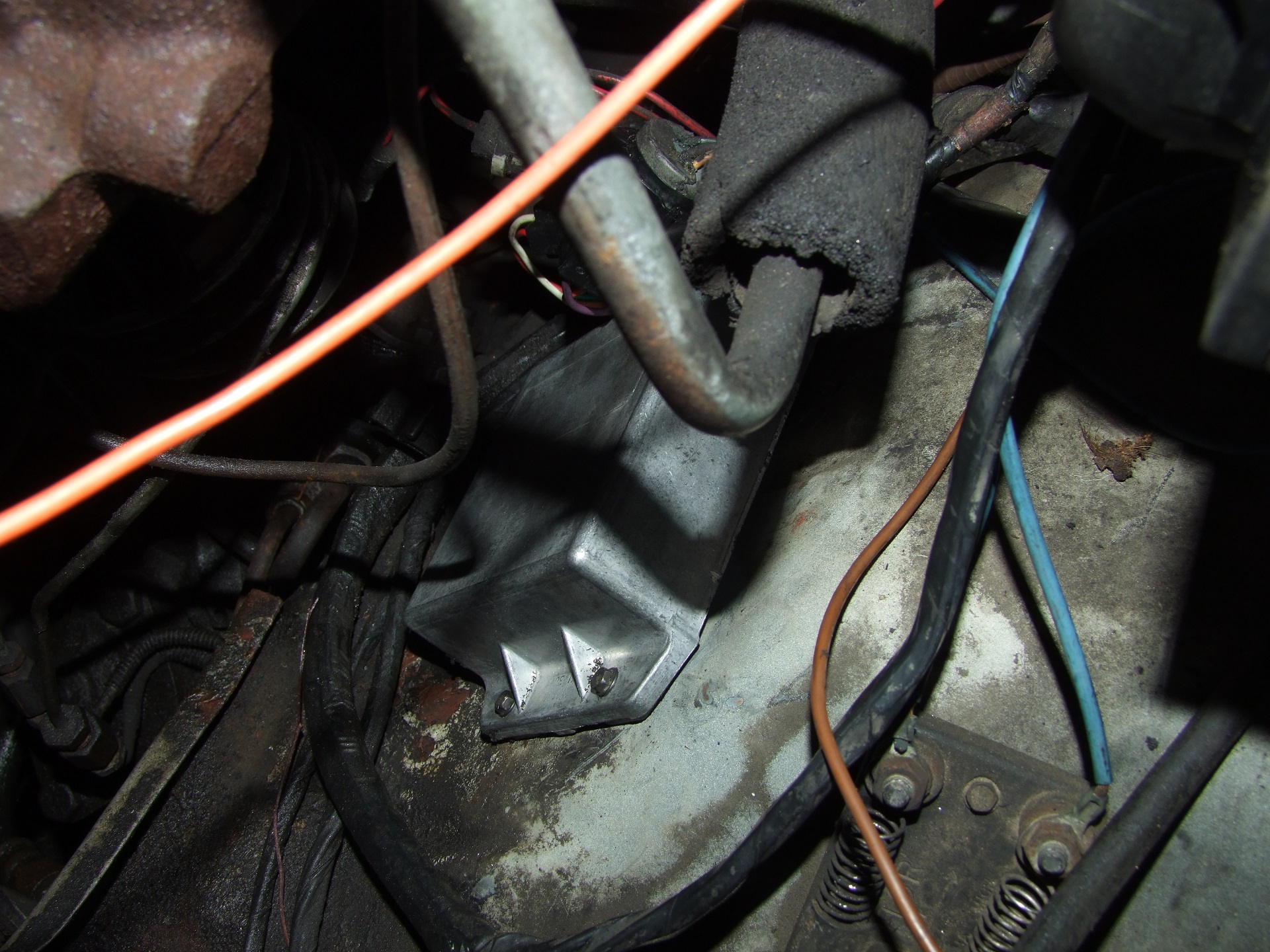
That’s the Ur-ECU ignition control module. I like how it’s just bolted into the wheelwell stamping like a good ol’ retrofit system that got put into production. “Looks good here! Build ’em like this!”
So this didn’t resolve anything. I started wondering about other electrical systems in the path of the fuel pumps. For some reason, there are a whole bunch, as illustrated by this handy diagram I drew in a fit of frustration:

I managed to locate and test the fuel pump cutoff relay but couldn’t find any trace of the fuel tank selector relay. Based on some more sleuthing, I deduced that the DPDT selector switch might have been wired directly to the fuel pumps. The object that says “NEW!!!!” all over it is this contraption:

Another one of those “Well why the hell did you do that?” parts on this thing is the fuel tank selector valve. It’s basically a small hydraulic solenoid valve that connects one circuit to two, but shittier and plastic. And it was the source of one of my troubles.
See, while bypassing the fuel pump power safety cutoffs, I did numerous impromptu fuel pump volume tests (because I wanted to see if it was pumping fuel with shortcut wiring). This led me to discover that some times, the fuel volume was low or nearly nonexistent. It would start off good, and then taper off. This actually corroborated a weird behavior I noticed where some times when the engine would start sputtering, I would wiggle the selector switch repeatedly for a few seconds and it would gain some run time. This was in fact one of the symptoms that made me think a power supply to the fuel pump problem.
Uh oh. Suspecting that this valve had been bad from the beginning despite me testing it on the bench listening to it turn over, I performed another volume test upstream of the valve. Both pumps were giving the correct volume, so I scrambled back to Pep Boys and picked up a new valve and spliced it in. I don’t know exactly what kind of failure mode it is – maybe the mechanism inside is sufficiently worn or damaged such that it might travel fine, but can easily be pushed out of position by fuel pressure. Maybe that causes it to backflow into the un-powered tank, or maybe it just plugs up and sits there.
The recurring lesson I’ve been learning from VANTRUCK is “BTDMIW” : But That Doesn’t Mean It Works. Just because I jiggled the component on the bench, or in isolation, doesn’t mean it actually is working correctly when installed.
But there was more! The fuel being pumped from the front tank, the one I personally serviced with a new pump and float – was rather BROWN. It was darker than what I usually knew gasoline as. Even more telling was that there was sediment on the bottom of the jar.
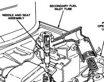
I instantly knew what was happening. The next thing I did was run around to the front and start unscrewing the carburetor fuel inlet line:
…and I sheared it off in the process, because I untwisted the first big nut looking thing I saw, but it was really the nut that went into that nut. Brilliant!
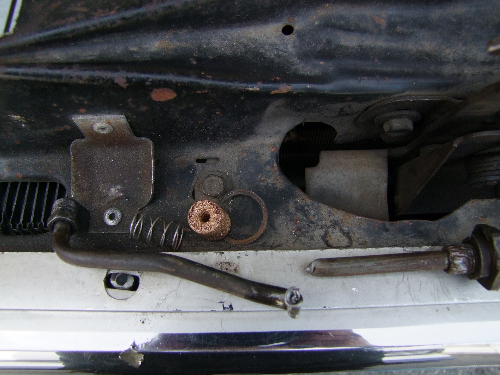
I couldn’t even blow through that little metal sponge. It’s the “filter of last resort” for the carburetor, and it had trapped in it all of the rust slurry being pumped from the front tank. You can see some of the visible grunge on top.
Dedicated readers might recall that I also replumbed the fuel tanks in the same operation that I replaced the front fuel pump in. Even more dedicated (or observant) readers will also notice that I did not install an inline fuel filter on the front tank. Why? Who knows?! Maybe I’m just traumatized by fuel filters. Maybe I thought the fuel pump’s jizz sock thing was enough.
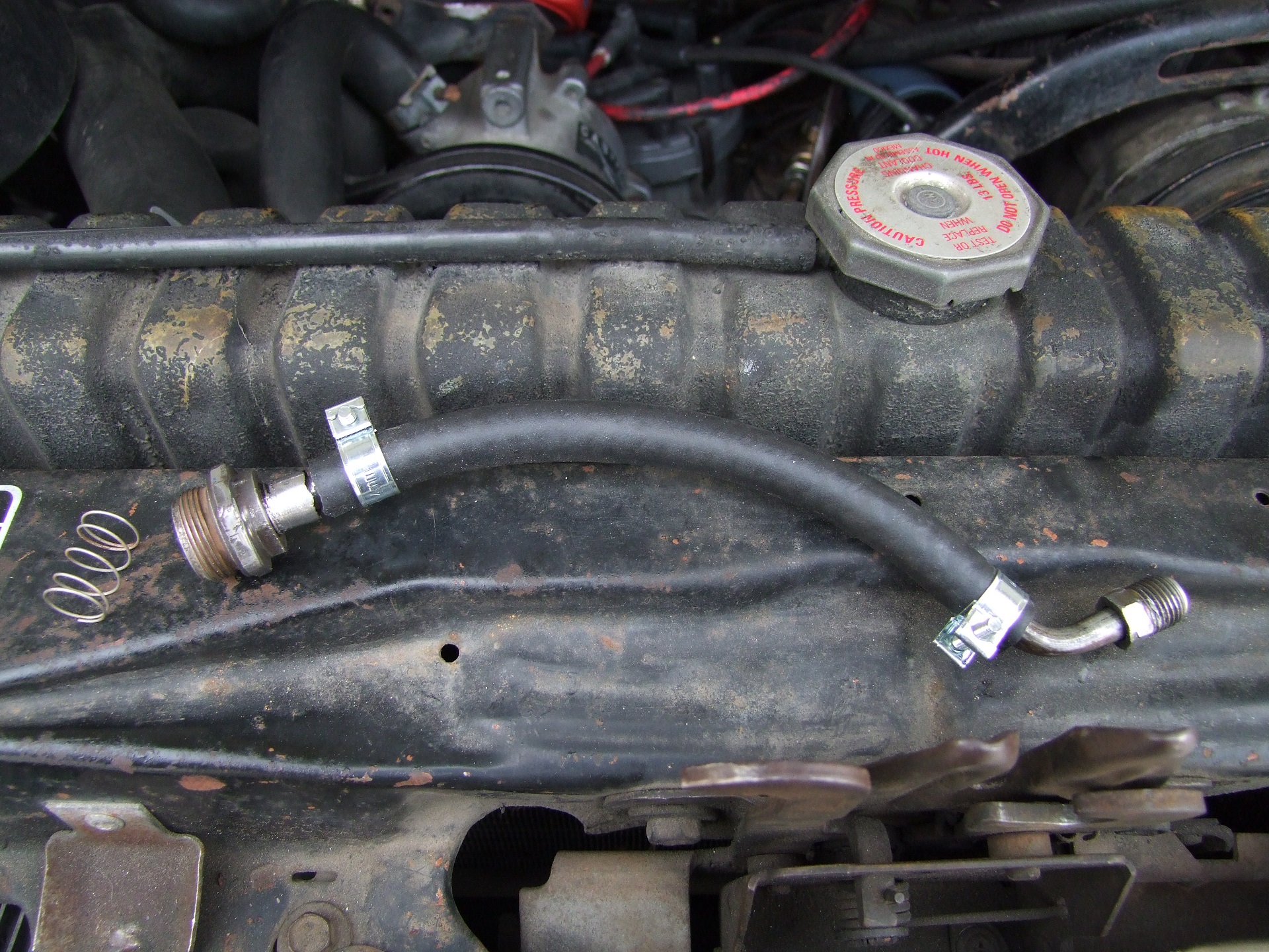
I patched this section of steel fuel line with some rubber hose and called it good.
Here it is installed behind the zinc-chrome part in the lower center. That is a “vapor separator valve”, or as I kept calling it, the vaping valve. It was bypassed earlier this photo series by a chunk of fuel hose. Unlike a modern fuel injection system where there’s a fuel pressure regulator bleeding off fuel into the return line, this is just a little pipe with a hole in it. Its nominal purpose is to prevent vapor lock by having fuel vapor escape through the little hole, along with small amount of fuel. Ford sells these in several hole sizes depending on how much you want your engine to vape and also to help modulate fuel pressure. What the hell? Almost every system on this vehicle in some way is analogous to touching a variable resistor to something. None of this is okay.
And you know what? It ran GREAT! Rev for days! Piss of the neighbors! A M E R I C A N P R I D E. Oh crap, what’s that smell??
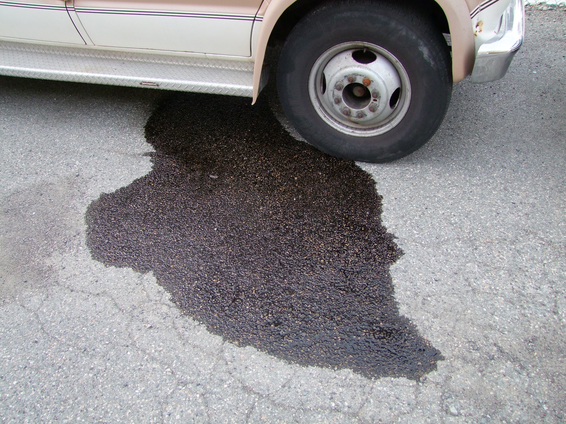
This is a giant puddle of BROWN that was slowly increasing in magnitude as I was having too much fun firing gun-wielding Bald Eagles out of the exhaust. Which, by the way, was backfiring (afterfiring) like crazy. It was clear the thing was running super rich. I now had literally the opposite problem as before. Hurray!
A little research showed that all of this BROWN was coming out of the vapor canisters. So much fuel was getting into the carburetor that it was coming out of, and flushing, the vapor collector lines and washing out the canister. Great! It’s like clearing your sinuses!
(The parking lot is still BROWN and smells like a freshly coated gym floor there, to this day)
So what was the cause? I dug into the carburetor manual a little after observing it with the air cleaner removed. That’s where I discovered another “tighten the incorrect nut” problem.
I found a little nut on the carburetor that I thought was left loose by the mechanic; since, you know, I kind of bailed it out of their hands before they could put it back together. So I tightened it. All the way.
Well it turns out that’s the fuel level adjust screw and accompanying locking nut for the secondary throttle (which only opens after about 50% throttle travel or so). All the way down is all the fuel, all the time, forever and ever. I noticed the secondary throttle discharge was completely wet even while idling.
This screw was adjusted more correctly.

And off we go! I went on a “Lap of I-95” test. On the whole, performance was excellent. I made a point to exit and then re-enter the freeway repeatedly to do full throttle pulls from ~25 to 70mph. It still tended to be a little backfire-y when letting off from high throttle demands. Given that the mechanic didn’t have a chance to properly tune and road test, I think something’s still a little whacky, but that is now an addressable problem.
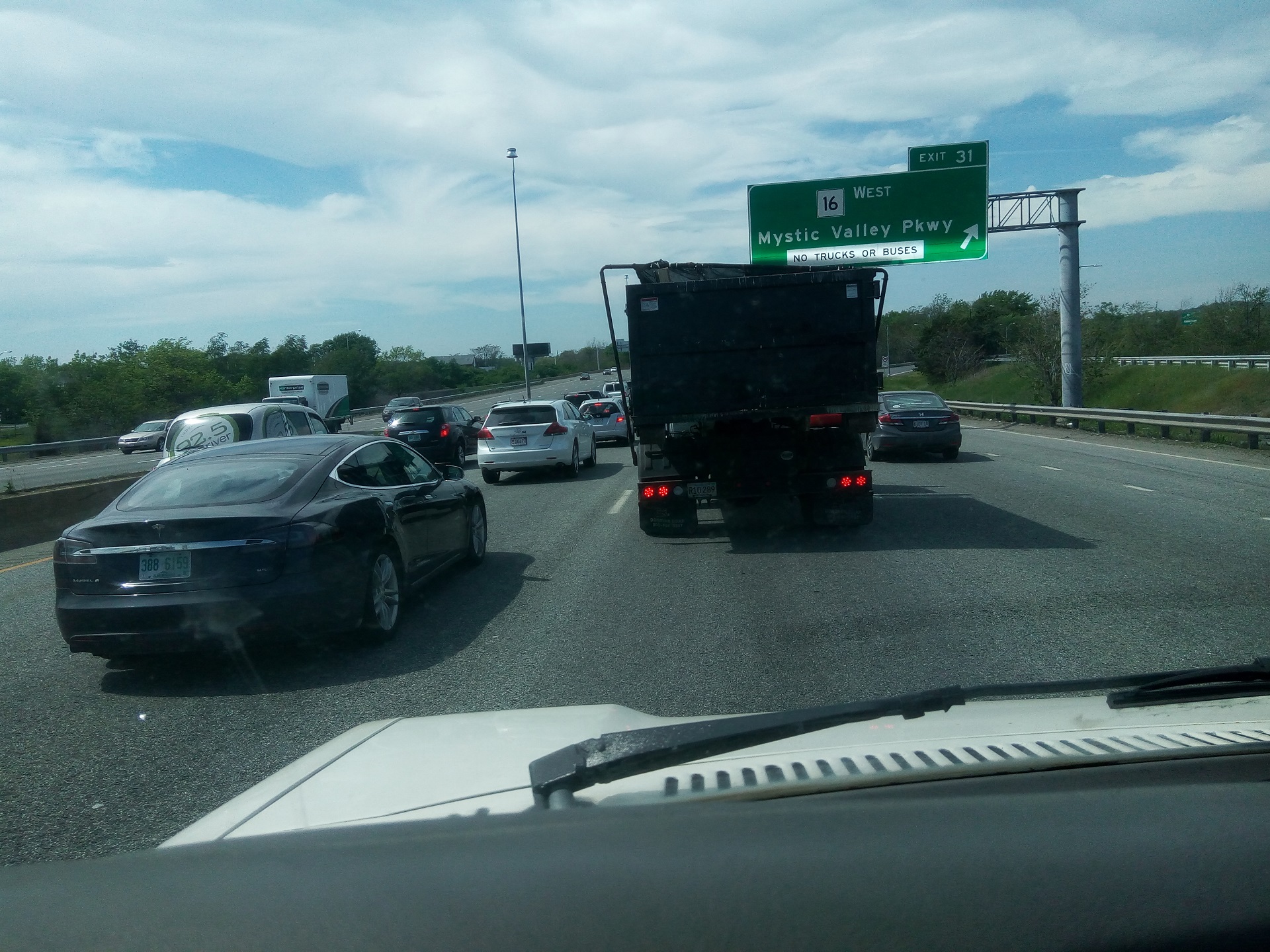
Hello, Mr. Tesla. Get in my belly.
In the end, I concluded that there had to be a very specific series of events and misjudgements for the running condition to get this bad. Here is my assessment of what happened:
- I replace the front fuel pump. Given that I had no lift and was working entirely on the ground without help, mostly in the dark, I didn’t drop the fuel tank fully and inspect it. I only lowered it enough on the straps to grab the fuel pump. Therefore, I didn’t see how much rust was inside.
- When the front fuel pump went back in, I neglected to install an inline filter on the output side.
- Filling of the fuel tank with new fuel, plus the force of the collision, likely washed a lot of loose debris into circulation, where it was picked up by the pump.
- I specifically used the front tank around town and during the Motorama trip attempt to ensure the system was operational.
- The carburetor began clogging with this rust slurry, causing me to abandon the Motorama trip as problems gently surfaced.
- Gradually, with additional around-the-town usage, it became worse as more rust slurry blocked the caburetor inlet screen.
- The particulate debris MAY have also affected the operation of the fuel tank selector valve – I am uncertain if it played a substantial role in the earlier problems.
- The mechanic was able to test for proper fuel volume delivery because the valve problem was a some times thing, which incorrectly ruled out the fuel system as a source of trouble. The Ford official player’s guide makes you only time the delivery of 1 pint of fuel as the test. I was pumping into a 5-gallon gas can and was purposefully holding the pumps on for a while in case something caused them to lose power.
- After the carburetor rebuild, I told him to continue testing using the front tank, because the rear tank was in an unknown state to me and had a non-functional fuel gauge sensor, whereas I said I had replaced the front fuel pump and fuel gauge sensor.
- Furthermore, for debugging systems in isolation, they bypassed the fuel tank selector valve completely and directly piped the front fuel tank to the carburetor.
- The carburetor began clogging with rust slurry again, leading to much the same symptoms and to the frustration of all involved.
- This timed well with me electing to cut my expenses and asking them to stop work.
So there you have it. Once again, one of my vans is stymied by the uncertain nature of fuel delivery. You know what? Electrons don’t need fuel filters! What are you gonna catch, some neutrinos?
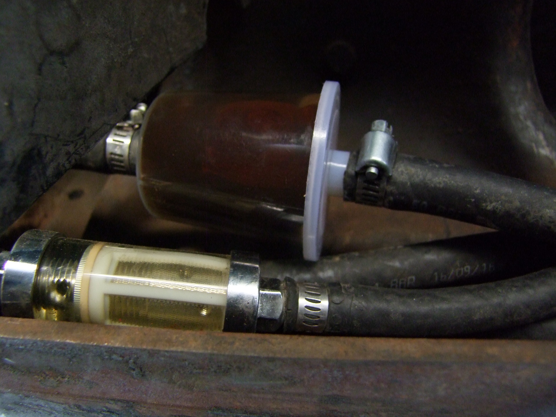
How bad is the front tank? Probably very. Before I turned anything on again post inspection, I went and bought the biggest clear inline filter Pep Boys had to sell and dropped it on the front fuel tank’s output line. That’s what it looked like afterwards. Delicious, delicious BROWN . I’m not likely to do any fancy fuel tank treatments to stop this. New replacements can be had for $100 or less, and as long as the bed has to come off, replacement will be easy. Plus, unlike Mikuvan’s filter, these two things are easy to reach, so I am likely just going to keep changing big plastic pubbles first and foremost.
Next time, the action starts for real:


