On this episode of “Charles is still CADing everything distressingly close to Dragon Con“, we continue with the development of Roll Cake to the point of completion, as well as begin with I CAN’T BELIEVE IT’S NOT OVERHAUL! Überclocker 4! I depart for DC 2016 in a few days, so there will hopefully be some updates on the physical construction of these bots on the road and in Atlanta.
So I spent quite a few days on and off puzzling over how to place components in Roll Cake. As I said last time, putting square things into a triangular robot often requires a lot of compromises and “dimensional exhuberance”.

This was one of the choice placements, using a 850mAh 3-cell lithium battery, the same kind used in Colsonbot. I also had a few 1000mAh ones used in Stance Stance Revolution, but they proved to be too long in every configuration here.

One of the other “mid experimentation” screenshots. I tried locating the battery on the same side as the drum motor. This involved pushing the drum motor to the interior of the bot, an option I was not favoring since it means the drive pulley was going to be pulling on the motor can farthest away from its bearings. This would end in certain tragedy.
Plus, it’s not like this side of the bot somehow had MORE length to put a battery in!

I decided on the configuration seen here after more component juggling. This places the battery in the flatter configuration (meaning it sticks out of the side more), necessitating making the whole bot wider by about 1/4″ to accept it. However, this meant the servo could be on the same side as the battery, which was highly advantageous.
Here, I’ve also generated the motor pulleys. The wheels were a design I already had; it is a little hard to tell, but the pulley sections have a V profile instead of the square bottom usually seen in small round-belt drive pulleys. I’ve found that this tends to give better grip for small pulley diameters, working a little like a V-belt. It also tends to be more tolerant of misalignments, since there is no square side for the belt to suddenly grab and be pulled off, and is also auto-centering.
The tires are a takeaway from Colsonbot and SSR, and are actually 1″ diameter rubber grommets (for sheet metal panel holes where, for instance, wiring or tubing pass through). They’re made of soft rubber and can be easily stretched over a hub. In this application, I’ve stretched them to being 1.25″ diameter.

Due to the tightness of the space around the battery, I did something I rarely do – simulate the chain or belt path. The 3/32″ roundbelt drive unfortunately has to make a Cleveland Left past the battery, in an area with minimal clearance. I specified and ordere some tiny little type MR63 bearings for this job – 3mm ID, 6mm OD.

Here’s the belt path simulated . It will need some grooves designed in into the frame to clear. I didn’t want to make the wheel pulleys any smaller due to the limitations of the round belt – too small a pulley and they don’t grip nearly as well.

The belt kink also allows the motor drive pulleys to achieve nearly 180 degrees of wrap. So at least I know that part isn’t going to be slipping! It also directs the belt up and away from the drum motor. I changed the drum motor to a slightly larger 2836 type motor which has a larger 4mm shaft. This desketchifies the pulley mounting significantly. The motor has been moved back to the interior of the drive pods, with the region around it beefed up in thickness and ribbed for its pleasure and rigidity.
All of the control electronics have now been moved to a pocket on the right side of the bot.

With the sides of the bot figured out as much as I care to, it was time to move to the clutch triggering mechanism. You know your unibody design has gone horrifyingly wrong when you have to start slicing the view to work on stuff.
The channel cut into the body here holds a sliding bolt-like structure which will be toggled by the servo.

Like so. This is shown in the retracted position, where the linkage holds the planetary gearbox’s output ring stationary and therefore the dog clutch ring spins freely.

And in the “This kills the servo.” position, where the sliding bolt impedes the motion of the dog clutch gear, forcing the output ring to begin spinning. This throws the cam linkage.
Based on the advisory speed of the clutch gears, which is 237.5 RPM (950 rpm/V * 11V battery / 2:1 gear ratio, then divided by another 22:1 in the gearbox) and the width of the valley between dog clutch teeth, the servo will have roughly 70 milliseconds to move the sliding bolt. These servos are rated at 0.11s per 60 degrees, and the bolt travel only needs about 15 degrees, so I HOPE there’s a healthy margin here.
The directionality of spin matter s alot. The frame is only bracing the sliding bolt in the configuration shown where the dog clutch gear is spinning clockwise. This means Roll Cake actually does have an “upside down” since the drum can only spin in one direction to use the flipping linkage. Hopefully, in a bigger version of the bot, this shortcoming will be addressed.

During this design work, I was thinking ahead a little as to how to 3D print the final product. The unibody turned out far too complicated to print in one piece, so I elected to split it into 3 pieces – left, right, and center.
One problem though. The bearing mounting supports for the drum, which are also the pivot points for the hinged flippers, make the left and right sides not completely flat if I sliced the part on the inner faces of the left and right sides.

I decided to make those rings a separate print each, allowing me to print the two halves concave-side up using no support structures, which results in a cleaner print.
Therefore, I added makeshift bolt holes on the inside of the drive sides, which eventually will have screws threaded through into the bearing mounting rings.

Each side had features added which allow me to fasten the side covers. Because the bot wasn’t symmetric, the attachment to the center U frame was different on the left and right.

One last detail was how to pass wires through. Besides the through-hole at the very back of the bot, which is supposed to fit a threaded rod (a last ditch everything-is-fucked way to keep the bot together), I put in two more semi-through-holes linking the left and right via the central frame. One will pass the battery cable, and another will be servo power and drive motor wiring.

I moved onto the final little details of the bot. Drums aren’t that effective without little feeder wedges to direct opponents into them, so I made small extensions that will mount metal — likely spring steel – wedgelets.

The side covers contain a few more injection-mold like elements to line up with the left and right sides. These will be made of heavily fiber-laden Onyx material as a desperate bid to fend off other weapons. Unfortunately the bot was already a bit overweight at this point, so no real armor here!

With the addition of the wedgelets and filleting every interior corner, the design is complete. To service either side of the bot, the five countersunk screws are unscrewed (the shoulder screw for each wheel axle is not bolted in, having clearance holes for the heads, so I can run the bot without sides easily and also not have to juggle wheels each service.

The hypothetical open position of the flipper.

And here is a “transparent frog” photo showing the incredible mess going on inside this bot. Like I keep saying, I’ll be damned if it does anything meaningful besides self-destruct.

And now I cut up the frame for 3D printing! Five parts total – two sides, the center U-frame (which will be heavily fiber-braced), and the two bearing support rings.
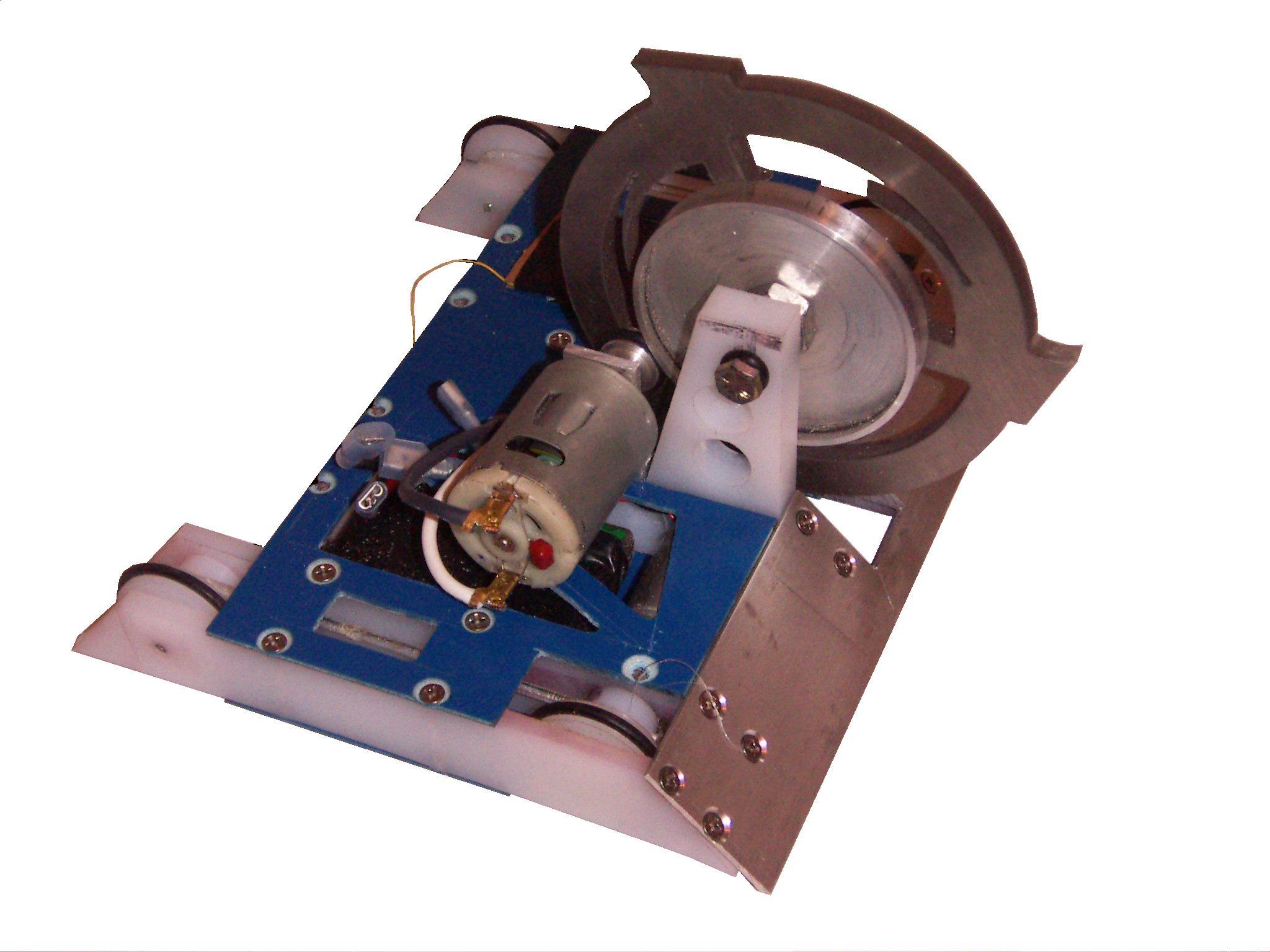
As a preview for what Roll Cake looks like IRL, here’s a pretend-o-bot from this past weekend. There will be build reports!

I CAN’T BELIEVE IT’S NOT OVERHAUL!
This post is now about wheels.
Hah, you thought you were getting a Überclocker design update. Well, in a way, it’s highly relevant, since I’m designing and casting custom wheels for this build from urethane resin and 3D printed molds.
One of the shortcomings of Overhaul this year at BattleBots Season 2 was the horrifyingly bad traction in the arena, compounded with my choice of wheel being poor for an overpowered drivetrain. I discussed a lot of this in the beta match recap. Basically, after the tournament, I was determined to investigate making my own wheels after seeing a few builders (including Beta) do the same. For me, the goal was less to get a specific wheel size or custom geometry than to find an alternative to the thermoplastic rubber Colson wheels, since nobody to my knowledge makes a real vulcanized-rubber 5 inch tire.
After doing some Internet Research, I decided the easiest way to start was to go with a polyurethane compound. There are many choices in that space designed to fit different applications.
Most of it, though, is optimized for some kind of mold making and so was hard to find relevant information for . That’s in fact one problem for me coming in as an outsider to the industry – I don’t know the industry words and niches where different terms mean different things. I tried finding natural rubbers and synthetic rubber base ingredients, as well as vulcanizing compounds (‘cure packages’) for natural rubber. But the only companies I was able to get ahold of were in the moldmaking & casting industry, and they’re so specialized that they didn’t know anything outside of the use of their product for moldmaking. Anyone with connection to the world of flubby substances is welcome to make recommendations – I really want to create a wheel with the same durability as a vulcanized rubber tire, like a car or go-kart tire, just with a softer compound. Now, slicing bits of tread off real tires and bonding/screwing into a custom hub is a possibility, but I really want to look at the next level up in elegance first.
As luck would have it, I was at the Detroit Maker Faire that weekend with the usual Power Racing Series crew. I had come only to help marshal the race and act as a tech/safety inspector – Chibi-Mikuvan sat out this race since I had not repaired the damage from last year’s New York Maker Faire. 10/10 would get sunburned again. I managed to get ahold of some Smooth-On company reps at a booth, so I got to hassle them with questions about the gooey substances they manufacture, including such cold-open gems like “So, what rubber would you use for a Battlebot wheel?” Based on the response, I’m apparently better at picking up middle-aged company sales reps than the ladies.
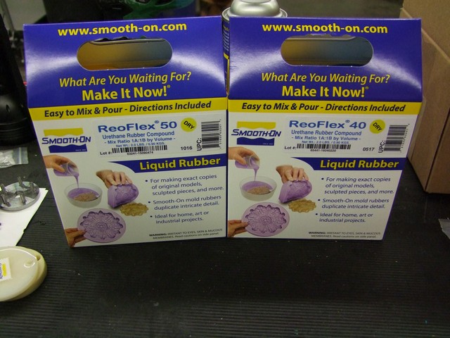
After 10 minutes of explaining what the hell it is I’m actually doing… since they’re mostly here again for the moldmaking and resin casting of tiny figurines and the like, two compounds came up very quickly – ReoFlex, a urethane rubber, and Simpact, a “rubberized plastic” as they put it. Both are, as far as I can tell, urethane-based. ReoFlex comes in softer Shore hardness ratings (20-50A) and Simpact in higher ones (60-80A). For reference, a skateboard wheel is usally 70 to 80A, a car tire around 60-70, and Colsons that are used in robots are usually their 65A Performa line. They were both recommended for higher tear strength relative to other similar products, which is important for wheel integrity.
So I went to Reynolds Advanced Materials locally and got a few hits of the stuff.
Lovely. Now what? Do I just pour one into the other and run for it?!
I next designed a core to hold onto the rubber tire. I knew nothing about this, and couldn’t find any good resources about “How to design cores for urethane rubber wheels”, so I freelanced based on what makes sense in my head. Those features were:
- Lack of hard square edges – gradual transition angles between rubber and plastic
- High surface area for good bonding
- No overhangs that can trap air bubbles
- Through-hole features to enhance gripping the rubber in case bonding fails

That’s what I came up with. Just a basic tapered V shape that has a bunch of through-holes around the permieter. I referenced the outer dimension of a 3″ Colson wheel, so if everything fails miserably, I can bail out to Colson wheels.
I desigend it so it could be 3D printed without support structures, so I can pass it directly from print bed to mold. Speaking of mold,

I then designed up a two piece mold that the wheel core sits in. The tread around the outside was added as an additional element to help traction in a box environment. The argument of tread vs. slicks has been a perennial subject in robotland, and now with my experience in the BattleBox, I think it’s pretty critical to increasing your effective traction. While a smaller bot like Clocker won’t really need it, I wanted to experiment with the molding aspect more, so treads it is!
The reason I think a light tread pattern is beneficial is because while you’re not trying to displace water or mud like in a road car tire, or grab onto rocks and dirt off-road, there is still plenty of fine powder-scale debris in the average arena. This debris is made of little metal bits, worn tire rubber, and SET SCREWS some times loose hardware. A tread that helps evacuate this debris would help put more rubber on the floor.
Tread design is one of those things I could spend a lot more time reading about than I had patience for at the moment, so I went for a simple helical groove pattern. The idea of the helical groove is to keep the contact patch relatively consistent (think meshing with the ground like helical gears) while trying to spread box debris sideways.

The mold was designed as one piece and then split into two pieces. Registration pin holes (not shown here) will keep the two mold halves aligned when together. A hexagonal bushing fits in the wheel and also keeps it centered in the mold.

By the way, I FINALLY, after literally 10 years, learned and used what Autodesk Inventor has for “part configurations”. In Solidworks, configurations are variations on a part stored in the same part file, so you can make different length standoffs, or different sized wheels, that each have the same feature history – no Save Copy As bullshit. In Inventor, this has been JUST barely out of my workflow path to be annoying enough and JUST stupidly named enough (SERIOUSLY? iPART???) that I have, almost on principle, never learned it. As a result, when I need to do a project that will make use of Configurations, I actually use Solidworks. And when I do my own stuff where my CAD file structure can be a Nightmare beta, I just Save Copy As or liberally spam Derived Components.
But that’s no more, because I watched a 5 minute Youtube video showing the basics of iParts, iAssemblies, and iMates, and just freelanced the rest based on expectations and mapping from Solidworks. So there! Now I’m fully Solidworks-free :p
And that’s how I made a 2″ wheel and mold just by editing some numbers in a table!
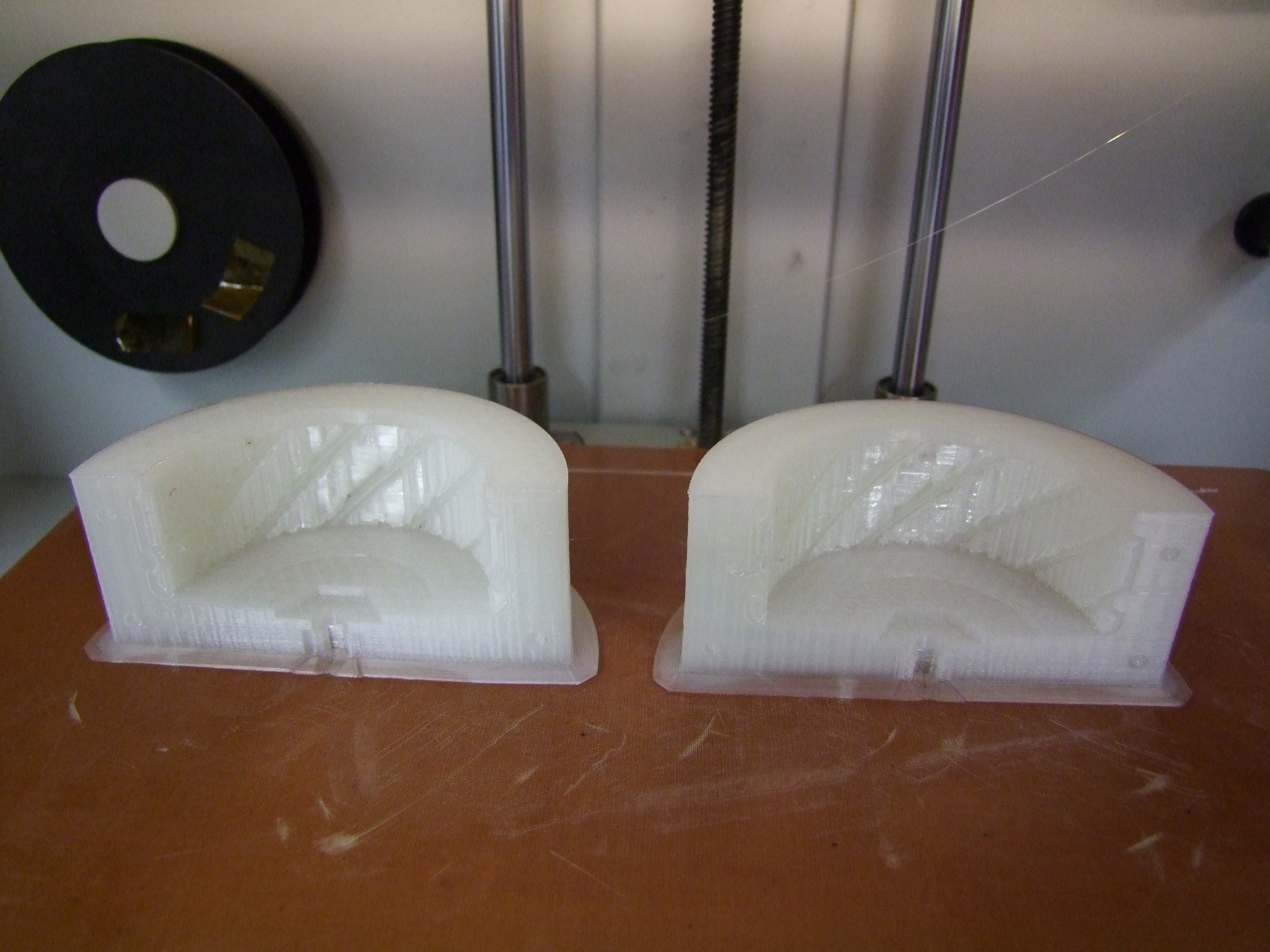
The molds were printed using the Mark Two machine in basic nylon, almost hollow. These didn’t need to be structural, after all, just quick to make.
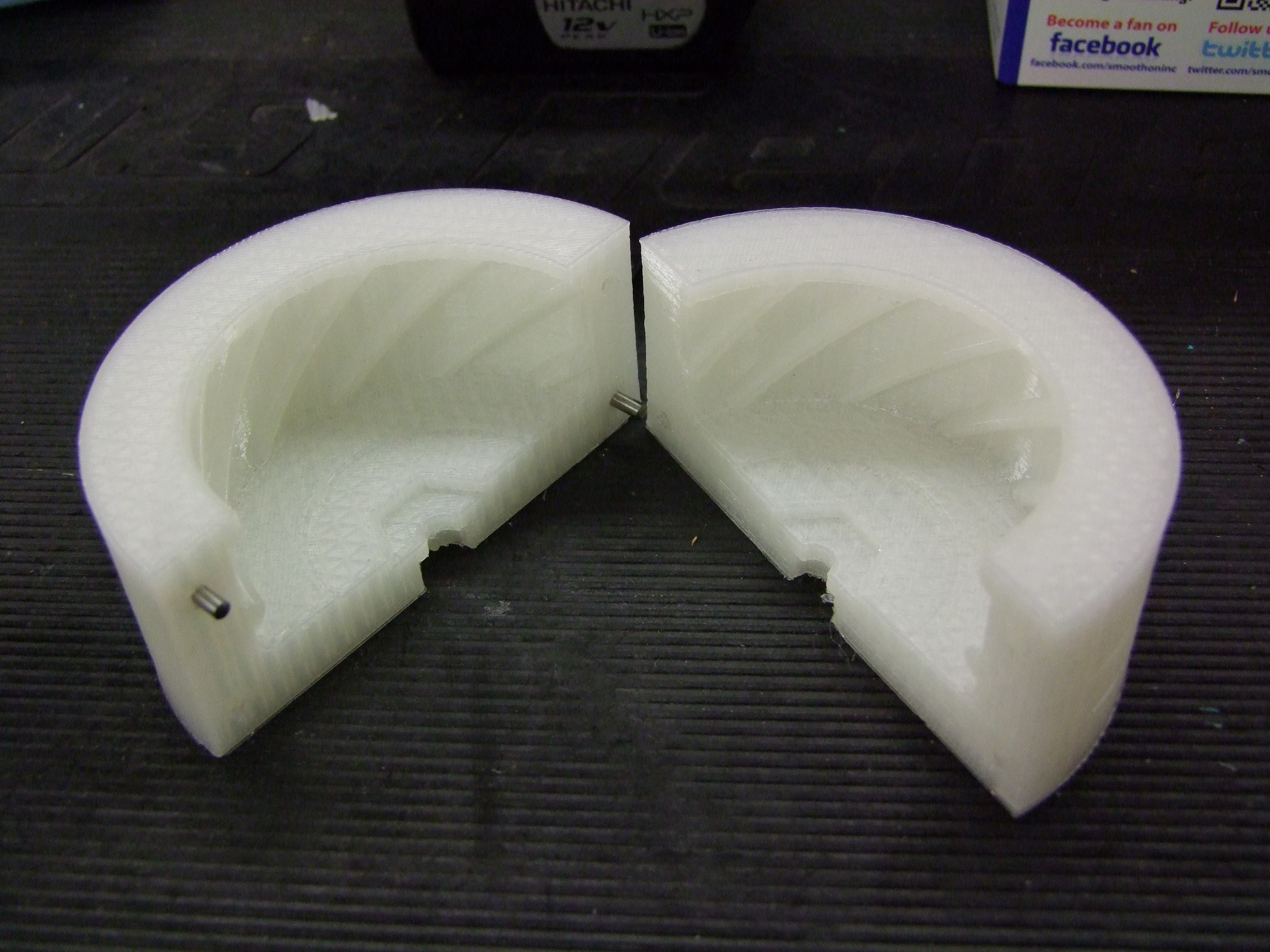
Mold halves with finish-sanding on the flat face (there was a small amount of warping) and installed registration pins.
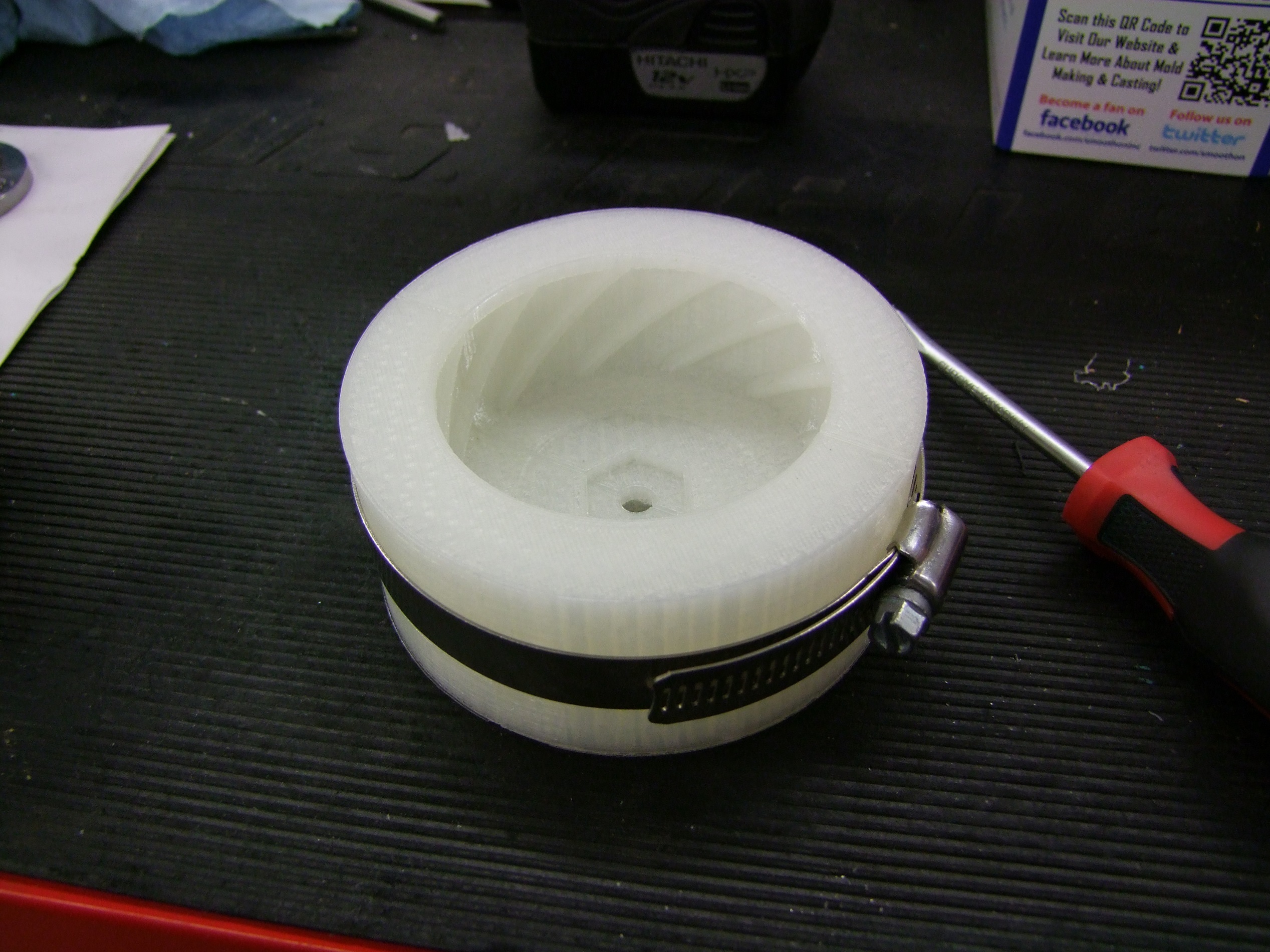
The retainment method is by a single hose clamp.
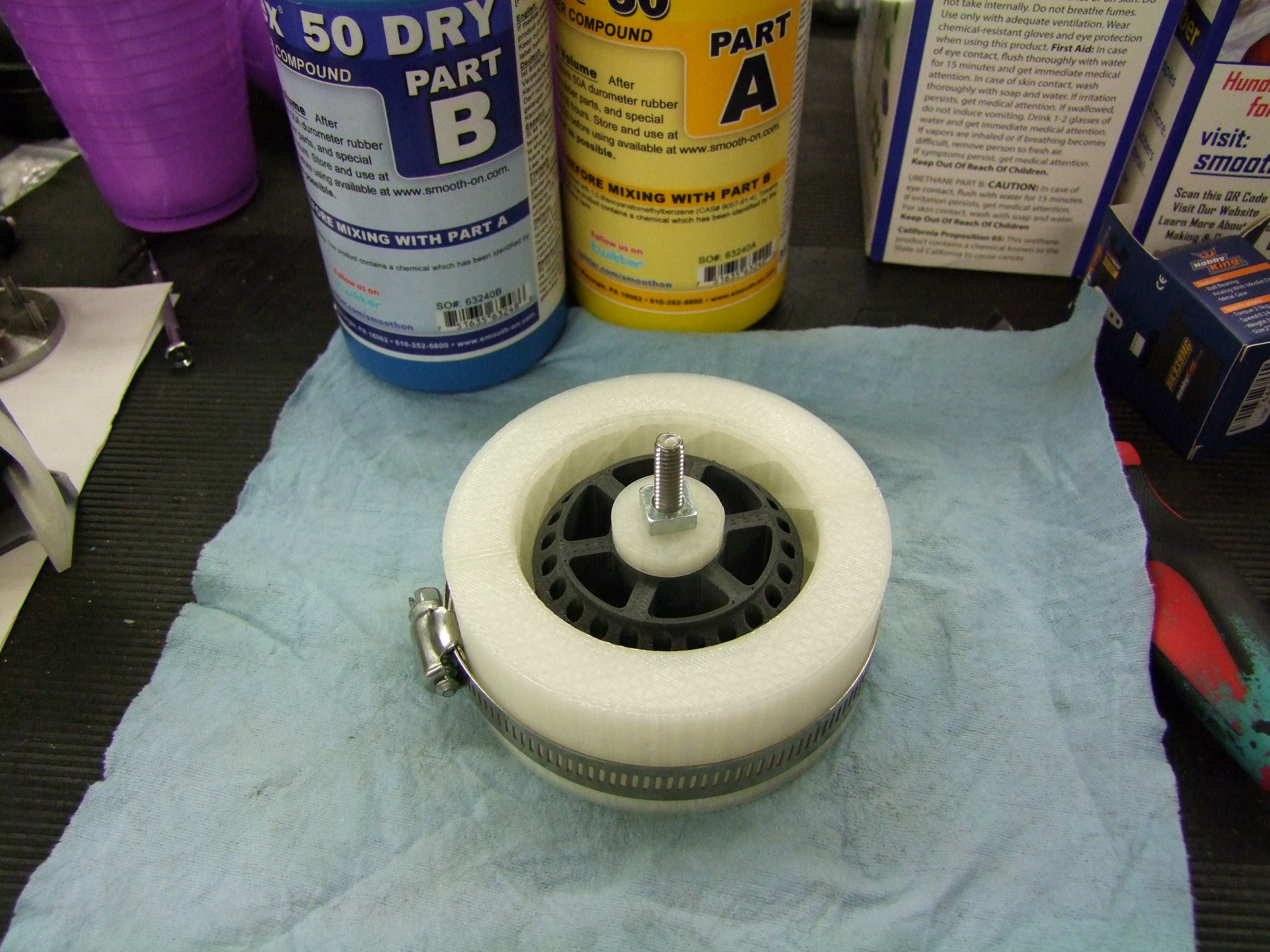
This is what the wheel looks like seated into the mold. A 1/4″-20 bolt keeps the wheel core tight against the bottom of the mold to prevent overspill.

I mixed up a dose of Reoflex 50 and put it in a borrowed vacuum chamber to pull out air bubbles. The mixing process introduces air, which makes your material basically a shittily-blown foam once cured and robs it of structural integrity (and surface smoothess & dimentional accuracy for people making cast objects from the material).
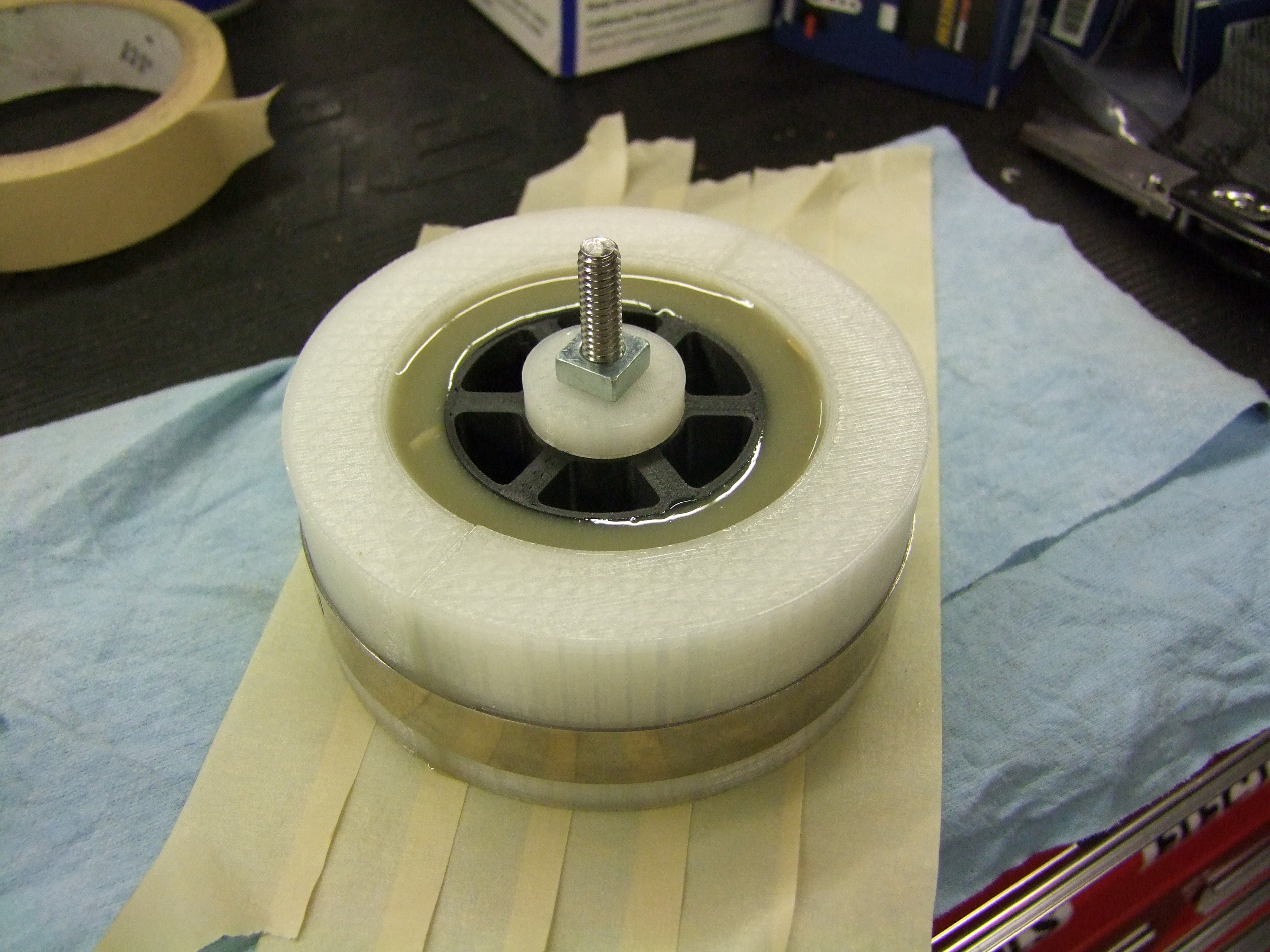
Next came the gentle resin pour. Simply fill to the top of the rim!
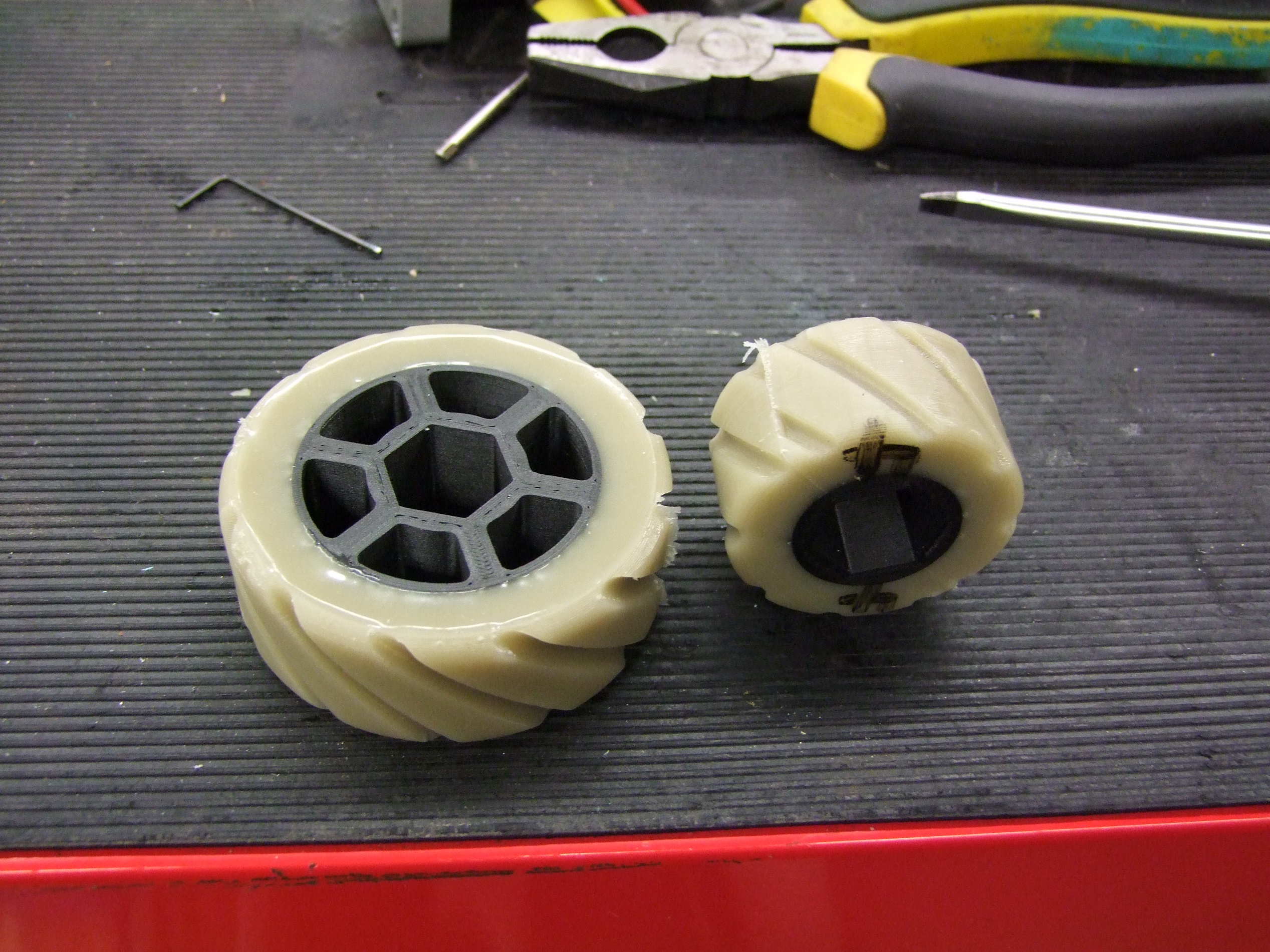
This is what the wheels look like. Pretty bland B R O W N color, but this can be pigmented if I so desire (Miku Blue wheel time??)
They feel pretty durable, but only testing will tell. This involves actually having a bot together to use them. So on the next episode: How to Scale your 250lb BattleBot and not Hate Yourself, a Self-Help Book by Charles.


