We take a short break from talking about Overhaul 2’s design in order to talk about something far more important: Ladies and gentlemen, from this day forward, I will be acting as the CEO of Marconi Motors, a company which will take on the likes of Faraday Future for the title of most overhyped bullshit of 2016. I even made a website! It even has a mysterious teaser on it!
nevermind that i swiped the product photo from Aliexpress and hurriedly pasted a Miku figure on the side
One of Overhaul 2’s defining characteristics which I divulged recently is its all-brushless, all-the-time drive system. Ever since then, a portion of the robot combat world has been going WTF? over it, which is the correct reaction, and I agree with it.
This post is extremely lengthy and detailed, so I’ve went ahead and split it into a somewhat coherent babble, instead of an utterly incoherent one like my preferred style. Here are the “sections”, but I heavily recommend just going to the bathroom right now, or declaring your lunch break.
Update: West Coast botmongler Xo Wang has put together a great writeup on the “behind the scenes” of some of this brushless controller shenanigans, and has dug into the firmware more than I have. Definitely worth a read if you want to know more about brushless controls in general and SimonK’s inner workings!
- Summary of brushless systems right now, and why they all suck
- Background on the idea and why I chose to pursue it
- Picking candidate parts for Sadbot
- Finishing Sadbot’s drivetrain
- Modifying the Dlux 250A controllers and tuning SimonK
- Testing and refining of the whole system
- Tips for chopping your own ESCs
Why does my motor need brushes if it doesn’t have hair?
Brushless motors have been in use for several years as weapon motors, especially in the smaller weight classes. Cheap ones – the venerable ICBMs, or Inexpensive Chinese Brushless Motors, a term you saw here first on etotheipiplusone.net in 2010, have largely been responsible for the rise of EVERY DAMN BOT LOOKING THE SAME optimal designs with spinning weapons – like vertical discs or “Tombstone-like” horizontal impactors. In short, they offer immensely improved power to weight ratios compared to DC brush motors, even high-performance thoroughbred ones like Ampflows.
The missing link to using them for drivetrains has been control. There have been brushless-drive robots in the past, even dating back to the original BattleBots on Comedy Central, generally using paired industrial controller & motor sets, but large scale (and expensive-for-the-time) R/C gear was not unknown either. Control strategies in this world of bots for brushless drive has generally been in one of three categories, discounting fully custom developed controllers by the builder (because come on, that’s cheating):
- Industrial servo drivers with similar industrial servomotors,
- Modified electric vehicle drives (such as e-bike or commercial vehicles), and
- High-end R/C hobby gear such as large marine / aircraft model controllers.

CrocBot, a 60lb design from the early 2000s.
Most recently, with the proliferation of brushless EV (such as e-bike) motors and brushless servomotors, more robots such as Overdrive and Chomp (ABC S1) have used brushless systems. These systems have become more ‘general purpose’ – you can usually plug one motor into another controller and have it either work, or require minimal tuning to work, but are still frequently sold as complete systems. The systems are usually limited in one way or another to reflect their industrial nature; examples include maximum controlled speed, motor stall protection, safety interlocks needing to be interfaced to radio systems, etc. In other words – yeah, it’ll work, but it’s a bit fiddly. Many things will work for robots if you are willing to fiddle. So that’s one constraint – ease of control implementation, and needing to be significantly invested in the details of operation of one particular system.
The second constraint of brushless drive is that of adequate operating envelopes. Hobby R/C motors, the ICBMs, are promising in their power to weight ratio and power to cost ratio, but hobby motor control equipment is not well suited for the task. Usually created for model airplanes, the controllers are lightly built, “rated” to an inch of the components’ lives using unrealistic methods, and usually do not feature reversing or the ability to maintain torque at low speeds and near-stall conditions, which is where DC motors shine. Generally, hobby motor controllers are not outfitted with any type of encoder or motor position sensor inputs, relying on motor back-emf sensing to start and run the motor, which means the motor has a minimum speed under which it will not behave. Yeah, your motor has to be moving before it can move. I know, right?! Those that are built to take Hall sensor inputs (such as these large R/C car controllers) will usually also not have current protection, so operating your motor near-stall will likely cook the controller quickly anyway.
The higher up in the market you go, generally the more robust the controller designs are, but that cost has priced brushless systems out of almost everybody’s reach except those who have easy access to them – like through sponsorships, or for whom money is no object. For the high-end R/C gear, the cost is generally high – approaching $1000 per controller, if not more, and of course you need at least two generally plus spares. Compare that with the cost of an average DC motor system for a 30-60lb bot: two DeWalt drill motors in mounts (Plug warning: like a DeWut, which I swear I will have restocked soon) and a controller to match might be under $600 total. Even for a Heavyweight of 220 pounds, two wheelchair motors and a set of Vypers runs you around $1,100 total. Cost is therefore the other constraint which has prevented widespread adoption of brushless drive systems.

Figure 1: Money money money money money
So the triangle of “choose any 2 out of 3” scenarios for brushless drive, in short, are:
- Industrial and commercial systems, such as e-bike parts, servo drives, and the like: DC-motor-like operation envelope, but expensive and often finicky.
- R/C model systems: Limited operation envelope, generally unrealiable, but plug & play (with price really all over the map)
The challenge is therefore to find or create a controller that can be used with virtually any hobby type brushless motor for drivetrain applications. Along the configurability axis, hobby equipment has a huge lead on industrial ones for the ability to “mix and match” motors, making them way better suited in principle for combat robots, which are generally bespoke systems not designed around any one particular drive constraint. Special requirements of drivetrains are the ability to handle inertial loads (recognizing that steady acceleration is necessary instead of forcible commanding a higher drive frequency, for example), rapid reversing, and DC-motor like near-stall behavior, if fully stalled behavior is not possible. And finally, it should be inexpensive enough to be worth investigating over a known DC motor solution.
It might not be optimal in all of the spaces, but it will be enough to make it worth my while.
And yes, I know that Radioactive used a plethora of NTM 50/60 motors with Hobbyking R/C car controllers for drive. But we don’t talk about Radioactive… :)
The origins of Brushless Hipsterism
I stood at the end of Season 1 wanting more from Overhaul’s drive system. Watching a lot of last year’s matches, and watching big bot tournaments in general, it seemed to me that the driving tactic in the bigger bots was more “point and shoot”. As someone used to driving 30lbers, especially a fast one like Überclocker, I had come to enjoy powerful drivetrains that can change speeds and directions quickly and which I can induce controlled sliding and rotation. I like drifting around and doing J-turns, and generally being swoopy and unpredictable. The best consistent drivers in the heavies know the dynamics of their own robots and use it to their advantage each match.
As a result, the wheeled drive modules of Overhaul, which we made knowing that the shuffler drive offered no advantages given the lack of a weigh bonus, was geared fast. Overhaul could hit up to 19mph, and overall I was satisfied with how the bot handled (with the exception of some squirreliness due to the weight being over the two front wheels only). I think the Lockjaw matches showed my driving style preference quite well, despite me constantly complaining that Overhaul drove like an overladen Chinatown bus.
But ultimately, that gearing turned out to be too hard on the Ampflow F30 series motors. Lacking experience with ‘big bot motors’, and having grown up watching winning bots use Magmotors (and their spawn, Ampflow), I poorly assumed they were virtually invulnerable. While we never overheated and cooked the windings, the brushes were the first to give out, taking out the commutators when they did. We basically came down to swapping out for spares every match as a precaution. In smaller bots, you generally toast the motor windings before the brushgear is damaged, so I was expecting this failure mode. I was dissatisfied that $300+ motors were limited in their performance by a quarter square inch of graphite.

Toasted Ampflow armatures from Overhaul in 2015
During late 2014 and 2015, some small bot builders had begun experimenting with using brushless drive with hobby controllers that were outfitted with a custom firmware written for DRONE RACING, BRO high performance multirotors. While I had glanced through their discussions, I wasn’t able to try it myself due to, umm…. certain pressing robot matters until well after Season 1 ended. I picked up some controllers which had been designed around the needs of the multirotor community and used them in Stance Stance Revolution. You can read SSR’s build report here about 1/4 of the way down where I talk about the Simonk-flashed controllers. Here’s a brief quote to save some searching:
They’re the “Afro” series from Hobbyking, and besides making me wonder how they came up with that name, I also really enjoy their extensibility. You see, the DIY multirotor community has been working on a better firmware suited their needs for years. They now have a massive database of upgraded firmwares for many of the ATMega-based brushless controllers. the Afro line evolved out of this community’s needs, and in fact contains a bootloader onboard such that you can upload new firmware using only the PWM wire – no need to try and find the programming pins on the boards. The firmwares offer many configurable options, including reversing.
Hmm. It’s piqued the interest of a few robot community folks, one of whom put together a guide on how to update the firmware to a “bot compatible” one. I performed these mods on my ESCs and did a demo video on how it affected a relatively high inertia load like a blade.
-me
The stage was therefore set for me to think about how to expand this to the realm of big bots. Quite a few 1lb through 15lb, and even the odd 30lber, had at this point used a SimonK-cracked cheap R/C controller to drive, to varying degrees of sucess. I got intensely curious over the end of summer about what the SimonK firmware does differently to make it more robust in starting detection and reversability (The answer would come as a surprise later…), and what made that curiosity stronger was the fact that there are many open-ended settings in the firmware. I wondered if these settings could be used to better suit the controller for heavier loads. Small robots are comparatively easy; that is, they have much less inertia, as well as a higher inertia to power input ratio (i.e. motors are more RELATIVELY powerful for the robot size). Many competitors got away with using stock SimonK settings or using minor modifications to braking settings, and I wanted to see if the same was still true in the 250lb range, or if I had to start tinkering with
It was clearly time for some experiments.
The Manchurian Shenzhenistani Candidate
As usual with one of my developments, multiple independent threads of projects and explorative experiments converged on something that I could move on improving for Season 2. In other words, there’s no clean sequential path from nothing to a successful brushless drive system, so you’ll have to get the whole story.
Having experienced almost all the failure modes of using R/C airplane motors in EVs through both my own projects and the go-kart class sessions (which means I’ve seen almost all the failure modes you can possibly imagine out of anything), I knew that the controller was going to be the limiting reagent. In robot fighting, you so rarely see brushless motors cook themselves before controllers. Why?
Modern hobby motors are usually well under 0.1 ohms of line to line resistance (the resistance between two of their three wires), which means anything you do will cause hundreds of amps to flow. The motors are no longer what’s preventing your systems from blowing up due to too much heat from current draw, so what’s next? Not really the battery either, because modern lithium batteries will also easily source many times their capacity ratings – could be hundreds or even thousands of amps from a larger pack – without blinking.
This is one of the things I taught in the go-kart class. You can’t really calculate torque and power any more from “stall” characteristics with the current generation of parts, because it will create unrealistically high results that cannot be reached. As a simple example, your motor might be 30 milliohms L2L, your battery a total of 25 milliohms for a moderately sized 6S (22.2v), and the motor controller an additional 5. The theoretical loop current that wants to flow is 22.2v / 0.060V = 370 amps.
The element in the middle, the motor controller, has to handle throttling all of these amps that want to flow, and without current sensing on most R/C controllers, powering into a stalled motor can result in pulses of high current that very quickly heat up and destroy the FETs, board traces, etc. So the controller has to be extremely oversized compared to the motor. Those R/C controller ratings mean basically nothing, by the way, much like the horsepower of a Shopvac (This is more true for the lower end than the high end of the R/C market – which tends to be rated more truthfully).
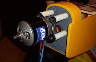
For the motor, I was most interested in the HobbyKing SK3-63 series of motors. These things are reasonably well built, and more important, have a rotor bearing (lower left) that helps prevent the can from coming apart at high speeds because one end of it’s unsupported. They’re also currently the largest motors HobbyKing sells that have the shaft coming out of the “correct side”. The larger Rotomax series do not have a reversible shaft without remachining, and they’re designed only to be radially mounted (sticking out of the front of the plane like the old style radial engines). By power analysis, they seem to be worth roughly 1 A28-150 apiece depending on what system voltage you run at, but weigh less than half of the A28-150.
Control-wise, I had to think a little harder. Luckily, I had a bit of a head start in this realm last year when I collected all of the large Hobbyking controllers to investigate their construction and power design THEY’RE ALL THE SAME GODDAMMIT WHY for the EV design class. As the product lifecycle of nameless R/C model parts goes, some of these are no longer produced or are “permanently out of stock” as HobbyKing loves to do:

Three out of a few more that I bought and unpacked For Science
The ideal candidate would have an ATMega series microcontroller to flash the SimonK firmware directly onto and be well packaged, such as in its own case with a heat sink. That pretty much took out the YEP (yep…).
It’s worth noting that all of these inexpensive big ESCs are pretty much genericized designs. They all use some pin compatible 8-pin, ~1 amp half-bridge gate driver like a LM5109 or an IR2101, driving a rail of MOSFETs per leg of the 3-phase bridge (between 5 and 10), with buttery slow switching times. The logic power circuitry is generally a chained linear regulator setup – none of these designs supply receiver power (BEC), so it just has to power itself. Some of them have SiLabs 8051 core microcontrollers like the C8051F367, and other an ATMega8A or 8L. I’m not sure entirely of the implementation difference that requires one or the other. The Aquastar and Fatboy both had SiLabs chips, which I didn’t have any programmers for on-hand; given that RageBridge is built off ATMega microcontrollers, I already had an Atmel AVRISP mkII and magical chip sockets.
The only controller that was left after this was the dlux 250A HV, which seems to be a visual mockup of the JETI Spin 300 Opto. It’s quite hefty – under the finned double-sided case are 36 IRFB3207 – my old favorites – in a weird upside-down hand-soldered TO-220 package arrangement. The other big ESCs used surface mount devices, whether a power 8-pin package or surface mount D2PAK.
My opening shot into leveraging Big R/C for robot drive was therefore the dlux 250 and the SK3 63/74 motor. As for which SK3, I played around in the Torque Calculator for a while to get a space of satisfactory results, also considering practical needs.
I decided to use the SK3 63/74-192 over the -149 variant. While I can get more torque per amp usng the 149Kv winding (it rises as Kv, or RPMs-per-volt, falls), I would have needed to run very high voltages, like 48v and up, to get satisfactory performance. I could instead use the faster winding and simply gear down more to trade the excess speed for more torque. To a degree, this “free power via high speed” is how R/C products claim ridiculous horsepower in small packages. Anything can push 10kW if it’s spinning at 40,000 RPM… doesn’t mean it’s remotely useful to do so.
The other practical restraint is that it needs to be easily interfaceable to Overhaul’s spare wheel modules and battery, which I had earmarked for this experiment. The motors were going to spin in the neighborhood of 7,000 RPM, so I figured they were probably going through a gearbox of some sort.
I also needed to put together a frame that held the wheelpods, and would end up weighing around 250 pounds. And that’s where the story of #sadbot2016 began, and where we pick up again now.
Finishing #sadbot2016
We pick up where we left off, which is mechanical completion of the frame to the point where I could start putting in the motors into the Overhaul drive pods. To do that, I needed to mod up some gearboxes.

Here, we have Collective Internet Gasp #17,385. The gearboxes I decided to use for this experiment are BaneBots P80s. First, because I had them…. well, isn’t that all the reason you need? Second reason is, I felt like they were a good size and power fit for the SK3 motors, which have natively 8mm shafts.
Last season, we used P80s on Overhaul’s lift and clamp gearboxes, which were mated to F30-150 motors, and they held up quite well. However, in that application, they were isolated from direct loads by the chain drive and ball screw. The SK3 and P80 make such a great sized package that I was determined to see if the lower ratios could be used as a building block for drivetrains. P80 gearboxes have been one of those “parts nobody talks about” in the combat robot universe because of an early reputation stemming from quality and materials. But they’d been redesigned recently, and I honestly don’t think they’re that bad any more. But how bad are they? That’s what Sadbot was supposed to find out.
To mount the SK3s, I needed to make two modifications, one to the gearbox and one to the motor.

The 8mm shaft of the motor needed a 2mm keyway cut into it. That way, the P80 pinion can slide right on. This is one of the reasons why I thought the P80 might be a good match, because there’s minimal shaft modification needed compared to the Ampflow motor, which has a 1/2″ shaft. For that, you can only use the 3:1 ratio (and multiples thereof) because the pinion has to be bored out and keyed for a 1/2″ shaft.
I had a bunch of 3:1 P80s left over from the Overhaul actuators, so I started with those, but ordered some 4:1 gearsets from Banebots in the interest of testing the effect of higher and lower ratios on the sensorless start, the conjectures for which I’ll explain.

I also needed to put the four SK3 mounting holes into the gearbox housing, which was easy enough. The motor mounting block was shortened to 1/2″ thick from 1″ (basically, where their octagonal extension stops). This put the SK3 shaft at basically the exact right length to engage the pinions.

Here’s a completed drive unit. See what I mean about how NICELY it fits?! The SK3 is barely smaller than the P80 – 60mm vs. 62mm, so I can still even bolt the P80 using its side mounting holes to a flat plate without the SK3 hitting anything.

A few more holes and this assembly is now bolted to the Overhaul drive pods and linked up with chain. I used a stock Vex #35 double-sprocket on the P80 output, like Overhaul had hooked up to the F30-400 motors., so this step was super easy.

Drive pods are bolted in. I added a bunch of rubber shock mounts for mounting the (eventual) top plate. They needed to clear the tops of the drive modules, and I figured in case this thing ever goes to a tournament for some reason, I should have a modicum of top armor. For testing, I planned to just use some plywood.

I cooked up this quick mount for the dlux 250s that jus theld two of them nested into each other. The switch on the left is a modified Hella switch that I made when I was fed up with breaking melonscooter’s Hella switch off every few months – it turns the Hella into something resembling a Whyachi switch.

Around this time, I got an intern. Here’s Mr. Hypershock himself helping wire up Sadbot, since he was also sort of vested in the outcome. Why? Well, because [ REDACTED DUE TO NON-DISCLOSURE AGREEMENT ] and that’s how we wanted to win against Tombstone.
Make sure to catch the Season Premier of Battlebots Season 2 on June 23rd, 8PM eastern, 7 central, on ABC, to find out…
Dcoding the Dlux

So we’ve gotten the bot prepared and all the bitch wiring power system work done by Will Bales. The thing that was left on the agenda was how to stuff SimonK onto the dlux 250. Time to bust out the AVRISP mkII… Luckily, I already had the fancy socket on it from programming Ragebridges. I already had the KKMulticopter tool ready since I’d done this for Stance Stance Revolution. As a reminder, basic reflash procedures are found in this AfroESC Guide for Robots & Dummies Alike document written by Lucas Grell.
In the Github repository (because…. open…. source…. uuugggghhhhhhh) there are some directions on how to discover pinouts of new ESCs in order to assign the correct pinout and change other settings like which pins to use to drive the FETs. I hammered this out in an evening using a multimeter and oscilloscope. For reference below, the signal side pinout nonsense of a dlux 250a controller:

Yeah if you know what that means, you’re ahead of me.
In short, there’s 4 main things you have to do to set up a compatible ESC for SimonK:
- Identify on which pins the six FET driver signals live. Phases are called A, B, and C, and the upper or lower half is notated “p” and “n” respectively. This is a bit of a carryover from earlier generations of R/C controllers that used P-channel MOSFETs on the high side of a output bridge for easy gate driving (yoink the P-channel low to turn on, easy to do from a ground-reference microcontroller). Newer ESCs use all N-channel MOSFETs, which are literally better in every way, either with special driver chips or discrete helper circuitry.
So “p” means HIGH SIDE and “n’ means LOW SIDE here. The six FET signals are An, Ap, Bn, Bp, Cn, and Cp. This is done when the controller is off, via pin-poking to check for continuity between a microcontroller pin and the input to the gate drive, whether it’s discrete (made of helper transistors) or a driver chip. - Identify on which ports they live – to do this, you need to cross reference the pins using the microcontroller datasheet. I just printed out the pinout diagram and scribbled on it, so I right away knew if it’s Port B, Port C ,and so on.
- Idenfiy what default polarity the pins are. Depending on the ESC and method of drive, it might need one set of pins to be default-high instead of default-low, with oppositely-conventioned PWM. If you get this wrong, things will probably blow up.
This is done by powering on the controller with the stock firmware and using an oscilloscope to check pin levels.If the ESC uses driver chips, chances are everything is default-low (which is what my “All INIT_Px = 0, no inversions” comments meant. All of the large ESCs I’ve checked that use driver chips are non-inverted. - Identify where the feedback voltages from the motor phases come back. This took the longest time for me, because there’s two intertwined connections going on.
First, there’s the phase leg divider shown in the graphic “Phase structure”. You start with the multimeter in Ohms mode on one phase output, and scout for pins on the microcontroller that read resistances to that phase output; typically it will be tens of kilohms, and they’ll all be the same value. That’s what Sense A, Sense B, and Sense C are on the microcontroller diagram.
What Sense A-C are also connected to is each other, through a “resistor star”. There was likely a pin on the microcontroller you found when you were trying to match up the phase sense pins that read some other, higher resistance value to the phase. Well, check that pin relative to the other phases, and it will probably be that same, higher value. This is the “virtual ground” of the motor. Note which pin this is. - Finally, the other kibbles remain – which pin is getting the R/C input pulse, and which pin is the bus voltage sensing line (and the associated resistor values to voltage input and ground).
Here’s what some screen of the kkmulticopter tool looks like with some of these settings for the dlux 250:


Your pin mileage may vary.
While the Github directions are sufficiently detailed, this is indeed a very daunting task to do the first time, but that should be the only time. So grab an EE friend…
Testing & Refinement
After arming up the firmware, we tried to confirm operation:
Hey, looks pretty okay! The stock settings would clearly work on a small bot, as they did for Stance Stance Revolution too, but it had some trouble with the Motenergy motor (“brushless etek”) which has a heavy steel disc rotor. Increasing the “start power” settings PWR_x_START helped, as did enabling COMP_PWM, which turns on synchronous rectification. COMP_PWM plays a large role in why I think any of this works, and I’ll explain why later.
After consistent behavior with the big motor, we decided to just throw it on there and have at it! Here is test number 1. Bone stock settings except for my changes to PWR_x_START.
Alright, enough excitement. I was truly surprised it could move at all.
From my motor controller debugging spidey-sense, there were two big issues in the video. First, the controller was still losing track of the motor during reversing and when I moved the stick quickly enough to try and start. Second, not shown in this video, it would reset on hard acceleration. Otherwise, it seemed to drive great, and so long as it kept moving or had enough inertial to keep both sides in motion, I could drive around as I usually would.
It was a proof of concept, but still needed refinement. Following this test, I actually reached out to the SimonK himself, through the e-mail on his website, showing the video and my (up to this point) detective work and asking if he had any guidance. Here’s an excerpt from my email:
> My question for you involves how to tune the variables to respond to
> ground applications better, which generally need much higher starting
> torque and a slower “ramp up rate” (since the load is largely
> inertial). I notice the bot has trouble some times if I punch the
> throttle stick from a moving start – the motors desynchronize
> repeatedly. Additionally, more power applied during the starting phase
> is beneficial, as is a lower ‘minimum speed’. To this end, I’ve been
> playing with the PWR_x_START variables to increase the starting torque.
> This has worked out well. I am now trying to study the code to see
> where I can adjust how quickly the motor speed may change (‘ramp rate’)
> and how to affect the controller’s minimum speed.
>
> I’m therefore wondering if you have some pointers as to which variables
> dominate what behavior of the motor. I’ve tried adjusting the
> TIMING_RANGEx variables, but this did not seem to produce different
> results, for instance. I also measured the switching times of the dlux
> so I could adjust MIN_DUTY and deadtime to better suit the large Dlux,
> neither of which affected motor behavior much.
Simon was actually quite responsive, and extremely helpful in his replies. Here are a few excerpts from his very lengthy and detailed responses:
We will probably need to discuss particular cases, since you mention two
things: motor desync when you “punch the throttle stick from a moving
start”, and “more power applied during the starting phase is beneficial.”
These issues often overlap. :)For greater low power range, lower MIN_DUTY to something like 6 (which is
about as low as it can go without just widening a zone of minimum duty).
This just makes up for some cycles lost while the hardware jumps to the
interrupt, etc. It is set higher than needed normally to overcome coggy
motor starting in most cases (not needed for car style things).…
You will probably get more torque/acceleration and maximum speed out of
MOTOR_ADVANCE=30, but it will cause more torque ripple and be less
efficient. I wouldn’t run it that high unless you’re trying to compensate
for gearing or some other issue.PWR_COOL_START is only used if it tries to start while rotor-locked. It
specifies the duty limit that is modulated in only to avoid overheat.PWR_MIN_START and PWR_MAX_START are the initial and eventuald duty limits
applied while in starting mode, which is the mode where we haven’t
confirmed timing yet, forcing MOTOR_ADVANCE to 30 while we figure out how
long any particular cycle is (needed to calculate an angle).ENOUGH_GOODIES is the number of commutation steps needed to presume
confidence in the timing feedback before we leave starting mode. You can
likely set it to 6 or something if you want to not be limited by the
PWR_MIN_START, etc., duties for as long (when starting from stopped).
But, 6 commutations should probably happen very quickly unless you’re
directly driving the wheels with no reduction, or something. :)PWR_MAX_RPM2 is totally unused (forgot to remove it, sorry).
PWR_MAX_RPM1 is the limit that is mixed in when timing is slower (longer)
than the TIMING_RANGE3 interval. This is another form of “starting ramp”
that limits the duty just based on timing, so as to avoid overcurrent at
low speeds if 100% duty is requested.…
COMP_PWM can certainly help take away some of the noise that otherwise
comes up on the undriven phase. The collapse of the current flow usually
results in some noise, and that is mostly masked by complementary PWM.
This makes starting a little easier, and it will run with less diode
conduction (less heating) at the expense of more torque ripple.…
In practice, the braking force and current will be highest at the
beginning, and in most cases the timing will be tracked the whole time,
usually resulting in some pull-back of the duty around the time of the
zero speed crossing…which isn’t as useful as if it did it at the start
of the direction change. To fix, a concept of a direction change really
should be introduced, and the ramp calculations should count spinning in
the opposite direction as a case twice as “strong” as when starting from
stopped.The ramp serves two purposes, though: making it easier to actually track
the back-EMF when it’s weak (nearly stopped), and for current limiting
for large jumps. A blend of the two is probably required for your case.…
This was all extremely helpful information, and probably makes sense only if you are also a motor control nerd. In summary:
- MIN_DUTY is the lowest on-time for the PWM generator (so not TRULY a “duty cycle” modifier, but on-time). I lowered it, but not by much. Essentially, if it’s too high, the motor will want to immediately start moving quickly, and the heavy robot on the other side won’t. I was going to have to adjust this way down – I planned to just see how low the duty cycle can go before the MOSFETs just stop turning on fully (and be a little above that for safety).
- MOTOR_ADVANCE is how many degrees (electrical) the controller “stays ahead” of the motor, which is important because every action – from switching MOSFETs to having current build up in the windings to it interacting with the magnets and the rotor starting to spin – has a bit of delay associated with it. The controller needs to therefore work a little ahead, so to speak. But it can literally get ahead of itself when at low speeds and near stand-still as to bump the motor back the wrong way a little. Increased torque ripple is a symptom of too high timing, and if the motor doesn’t start moving quickly enough but the controller is convinced it did, it could actually push the motor back the wrong way.
- I was correct with the behavior of PWM_x_START, but I was confused as to what they meant and did, which was cleared up. It seems that PWM_MIN_START and PWM_MAX_START are the ones that really dominate the behavior, so I was comfortable in cranking them up.
- The “braking force” he refers to are the settings BRAKE_POWER and BRAKE_SPEED in the firmware assembly file. These control how quickly the controller ramps the motor down if a decrease in speed is commanded. Absent a current sensing method, this is the “open loop” way to get a variable braking effect.
- Combined with COMP_PWM, synchronous rectification, increasing BRAKE_POWER and BRAKE_SPEED causes the motor to track its ideal unloaded speed according to the PWM duty cycle (if it were drawing no-load current and just spinning attached to nothing) more closely. Effectively, this translates to the robot trying to go exactly as fast as the stick command, all the time. If it was travelling faster than the command, the PWM duty % would be lower and it would act as a brake, and vice versa, with BRAKE_SPEED commanding basically how much “lag”.
My conjecture was that COMP_PWM with maximum BRAKE_SPEED, decreased MIN_DUTY, and increased PWM_x_START was the key to making it work well for heavy loads, at least from the software side. This causes the motor to start spinning more slowly, but with more initial punch, and try to force the robot to track your transmitter stick position by active braking instead of letting it coast.
There was only one thing you as a driver had to do in this case, which is to not mash on the stick like an idiot. Smoothly bringing the commands across zero (reversing) was needed, so the robot can brake, stop, and then start again in the other direction. Having driven bots almost exclusively since the Ragebridge Era using synchronous rectification ESCs (COMP_PWM), I was already used to this and preferred it even back when controllers had shitty “ALL MOSFETS TURN ON” braking at neutral signal.
So let’s get to work. First, I decided to measure both high- and low-side PWMs at once using the 4-channel oscilloscope to check the switching time and deadtime. One trap of COMP_PWM is if your FETs don’t turn on and off quickly enough, they’ll cross conduct and reduce themselves to the simple case of touching your battery leads together. This kills the MOSFET, among other things.

In this screenshot, yellow is the low-side FETs of one phase leg and red is a differential measurement between the phase output (midpoint) and the gate of the high side FET, and it shows the switching timHOLY SHIT, THERE’S SO MUCH OVERLAP HOW ARE THESE THINGS STILL ALIVE IT’S ENTIRELY MADE OF SHOOT-THROUGH
Hmm, well, that would explain why the ESCs got so hot running the bot when we were pretty gentle with the throttle. Like I said, butter-soft switching times keep these controllers alive…
So that’s with DEAD_LOW_NS and DEAD_HIGH_NS at the default 300 nanoseconds, which is no.

I adjusted it out to 1400ns (shown in this image is 1300ns) to give a comfortable margin between the high-side turning off and low-side turning on. In this same setup, I also tuned the MIN_DUTY all the way down to where the yellow curve roughly ends now, which was 16. Based on the MIN_DUTY and POWER_RANGE variables now, this resulted in a roughly 2% minimum duty cycle. I probably could have shaved off more, but FETs not completely turning on will negatively affect the starting behavior.
After changing the other variables mentioned, it was time for drive test number two:
Massively improved behavior!
At this point I think I was hitting the limits of hardware. The software wanted to perform, but now that we’re pushing the bot harder, the controller is resetting constantly. Fortunately, the deadtime setting helped elimiate the heating problems entirely. After this drive session, the ESCs were still cool to the touch! So that’s what happens with your MOSFETs aren’t scientifically shorting the batteries 16,000 times a second.
I knew from my own controller designs that the amount of DC bus capacitance mattered immensely for the controller’s survival. Capacitors are a fast-reacting local farmed 100% natural and organic non-GMO source of electrons for the immediate switching of bazillions of amps. Without enough capacitance, those electrons have to come from somewhere, and that usually involves getting sucked through comparatively small-diameter wires, causing voltage sags and spikes as the FETs turn on and off. These ripples mess with the stability of everything. There is literally not a thing as TOO MUCH BUSCAP, and the vast majority of R/C hobby controllers are under-capacitored by like a whole order of magnitude.
I had to remove three of the five capacitors on the dlux 250 in order to get access to the microcontroller – they’re soldered on AFTER that shiny aluminum case is put together! There wasn’t much I could do for now – I ordered some hardcore electrolytic capacitors – UCC GPD series, in the same size but much greater capacity and ripple current than the unknown Chinesium caps on there. The original capacitors were combined 2350uF (5x 470uF), and just two of those are 4,400uF.
But they wouldn’t get here for a while yet. For now, we’ll have to take it easy in testing. I turned my attention to finishing the rest of the hardware, since Sadbot was also to test one more thing for the still-being-designed Overhaul 2.

Let’s put together the pokey stick! The item that I was machining in the last Sadbot build report has been welded to the 1.25″ cross shaft.

Here is a third P80 +SK3 module mounted to the frame of the pokey stick. I was also going to employ the SK3s in the lifter for Overhaul, so I wanted to test what kind of gear ratios I needed. Sadbot was designed explicitly to use the same gear ratio on the pokey stick and the same arm length as OH2 (at the time).
To design the gear ratio, I actually approached it from the speed perspective. A lot of gear ratios in the high tens to low hundreds-to-1 would have worked if I were okay with the SK3 guzzling a hundred amps to do so, which it will happily do. But to give the design more room for error, I limited the maximum speed of the lift to a combination of something that sounded sane to me – around 3ft/s as well as was an easy ratio to make using sprockets. I ended up being the most happy with 192:1.
At this ratio, the SK3 only needs about 70 amps to lift the designed mass at the end of the stick, and it was an easy combo of a 16:1 P80 gearbox (which I had on-hand from Overhaul’s actuator as a spare part never used), a 4:1 chain stage, and a 3:1 chain stage.

The frame is bolted to the baseplate using a bunch of cap screws (the vaguely H-shaped pattern on the upper half of the bot). Even though this is a lot of steel, I’m fairly sure in actual fighting conditions the baseplate will warp since it’s holding on to the pokey stick frame entirely by itself, so if I were to rumble this against the Boston-based 250s later, I might weld in some frame reinforcements.

And that’s basically it! At this point, Sadbot weighed around 235 out of 250 pounds. Stuffing some controllers, heavy wiring, and a top plate ought to bring it to around 240, close enough fo rnow.

I cooked up a new ESC mount for three dlux 250s on the Mark One (this was all back at the IDC prior to me leaving), and also a switch mounting bracket. This device stacks three dlux 250s on top of each other and sandwiches them together.

An alternate wiring scheme was also needed, since I was no longer just connecting two ESCs and the ring terminal stack on the master switch was getting too fat. I dug around in my wiring products cabinet and found an old audio power distribution block. It split a single 4 gauge wire to four 8-gauge wires.
After whipping everything together, it was time for test number three, now with 100% more pokey stick!
Ouch. Well, something was sure unhappy…

The post-morten of the failed ESC shows an average HobbyKing afternoon barbeque with your friends “Lack of gate protection on the MOSFETs” and “Poor PCB layout and component arrangement”.

But that asshole “Not enough buscap” keeps showing up even though you didn’t invite him.
I think I can identify the exact point while driving when these capacitors let go, to be honest. The bot went from driving smoothly to suddenly “cogging” (missing starts).These capacitor leads are obviously made of steel. They’re magnetic! That should tell you about their quality in general, really.
It was clear that with the firmware tuned so rigorously that the hardware could no longer keep up.

Luckily, my Übercapacitors showed up. Honestly, I want to replace all five of the former caps with these. Two might be enough by capacitance, but even their wires can only handle so much ripple current. It was a short job to replace all of the remaining caps inside the ESCs for now, and I could think about how to add the rest back later.
To my horror, I discovered that during the drive-and-poke test, all three dlux 250s had at least one melted capacitor. May Brushless Robot Jesus save me.
The one that let go had both capacitors fail.

While Sadbot was taken apart for surgery, my 4:1 Banebots P80 stages also arrived, so I went ahead and swapped them out. This drops Sadbot’s top speed down from ~18mph to ~14mph. You know what? I’m fine with that.
A higher gear ratio means the motor has more leverage against the load, which helps in starting reliability. One of the things I taught in the EV class was this caveat for designing your drivetrain, which affected only the students who chose to go with R/C systems and sensorless drive… Hey, once they got going, it was great… They just had to do the “hump-in-place” dance to get going.
It was time for the ultimate test of ultimate destiny. Added capacitance (relative to how much they started with, hence the +2000uF you’ll see) and no further settings changes. The test subject, a piece of crufted lab equipment, weighed around 100 pounds – it was some kind of shaker table for chemistry magic, so it had a very heavy cast iron frame inside.
Result? Absolutely gorgeous, in my best Steve Irwin voice possible. I honestly forgot half of my own driving advice here and was handling it almost like Uberclocker.
What happened at the end? Well, inexpensive robot gearboxes gonna inexpensive. The P80 shaft is only retained by 1 snap ring on the inside, which got levered out from the rapid reversing loads of throwing the shaker table around.
I pulled the gearbox apart for a post mortem:

This was after I pushed the shaft kind of back in. Notice also the deformation of the D-shaft. This is another limiting factor which will affect how much torque you can push through these. An industrial planetary box like an Apex or Parker might have a one-piece machined shaft, or a shaft that fits into the carrier with huge splines. A D-shaft will concentrate stress of torque transmission onto the vertices of the D, and they’ll start deforming. The mating D-bore in the output carrier fared much worse because of the shaft being mushed out of it.
This is actually a good destructive test of the P80 for the Overhaul 2 build, so it will make me strongly consider how they are mounted. It seems like the P80 will definitely need dual-support for high torque loads, instead of just hanging a sprocket off the motor (single support)

For further testing, I was going to haphazardly dual support the output shaft on the other end. I used the Mark One to 3D print this fiberglass-reinforced nylon bearing bracket.

The bearing bracket anchors into the baseplate and braces against one of the unused slots in the pokey stick frame, and grabs the shaft with a shaft collar. It looks sketchy, but entirely resolved the “shaft exploding out of the P80” problem in further tests.
Unfortunately, video of these further tests weren’t collected, because by this point I’d gotten too spoiled by Sadbot working too well and would casually whip it out and impale dumpsters practice driving.

And here is the finished bot. Sorry BattleBots, this is all you’re getting. No Overhaul for you.
That top plate was a piece of 1″ thick UHMW plastic that I recovered from a group getting rid of materials. It was cut out of a larger piece using the CNC router and then “cut interior features to fit” with a jigsaw. This is actually pretty damn serious top armor in the realm of heavyweight weapons that exist right now! The total weight of the bot in this photo is 243 pounds.
During January 2016, Sadbot was moved to the Artisans Asylum along with the rest of my robot stuff after I left my job as IDC shopmaster.
Lessons Learned and So Can You!
Wow, that was a FRIGGIN’ YUUUUUUUUUUUGE build report, and probably a whole lot of material to go through. After finishing Sadbot and testing, I was entirely confident on using chopped up R/C model brushless parts for Overhaul 2.
Let’s start with a quick cost breakdown, not including “head-desking time” a.k.a nonrecurring engineering costs, which is basically the pains of developing unit #1.
- SK3-6374 motor: $80
- Banebots P80 4:1 gearbox, standard shaft: $90
- dlux 250A HV controller: $210
For around $380, I get a small gearmotor that weighs 4.5lb (add 1.5lb for the big controller) which can push, by my visual estimates as well as via the Torque Calc, basically equivalent power and tractive force to the twin F30-400 drivetrain of Overhaul with a vast majority of the operating envelope. More testing will obviously be required from here to get a feel for the more long term reliability, especially of the P80s’ output shafts. Additionally, Sadbot has yet to complete the “drive off a loading dock test” to shake up everything.
Recall that all of this testing basically went on while I was working on Overhaul 2’s design, which is why you saw the SK3/P80 combination right away in the first CAD post.
So, to break down all of the testing and info presented here into a “How to” format. First, some caveats before you think brushless drive with Hobbyking gear is the harbringer of the robot apocalypse:
- Brushless drive isn’t for everyone, yet. This is just one highly experimental implementation and only one branch of hardware testing out of many. There may be no hackable R/C hobby ESC which works best in all three domains of adequate operating envelope, reliability, and cost. Custom hardware might need to be developed to maximize all 3 of these needs.
- The shortcomings of brushless motors remain. Even if the motor can push as much power as one three times heavier, it just means the power wasted as heat is being put into a mass three times smaller. Brushless motors win in power to weight ratio for sure, but even though they are more efficient (often 20-30% more efficient, up to 90-95%), they can draw much more current and heat up much faster. I will need to make sure that Sadbot can run for 3 straight minutes of hard driving and not toast the motors – so far, they’ve been good, but this was outside, in January, in Boston.
- Gear low, not high. The more opportunities your ESC has to read your motor before it faceplants into the robot’s inertia, the better. That means possibly choosing a faster Kv motor over the lowest possible Kv (or RPMs per volt input rating), and gearing down more than you otherwise would. Furthermore, “chain slop” or drivetrain backlash is less preferable as a cheat to get around gearing – since once the ESC starts the motor and begins to estimate its speed well, the motor might just, once again, run into dead-stopped robot.
Spring-compliance is preferred to “deadband compliance” a.k.a backlash. A high-ratio planetary gearbox, for instance, gives plenty of springy compliance, as do long-but-tight chain drives, or rubber belt drives. Spring compliance is where the whole system still transmits the forces, but stretches and unstretches smoothly to effect more gradual motor speed changes. - I still wouldn’t use this in a pushybot, says Charles, as he designs an all-drivetrain Battlebot. The region near zero speed is still a minefield with sensorless controllers. Your driving style has to change a little, and every small bot builder which has used the AfroESCs and other hackable controllers in the 12/30lb classes will agree. Basically all of these bots have been weapon platforms, which brushless drive helps by being super light weight and power dense in a bot which does not demand all from its drivetrain.
Next, here are some tips if you want to peek inside your surplus stash of massive R/C airplane controllers to flash SimonK onto them.
- Increasing PWR_x_START increases the initial current into the motor, aiding starting. The more important ones are PWM_COOL_START, PWM_MIN_START, and PWM_MAX_START. I don’t think cranking these all the way up to “Max PWM %” will help, but certainly moving them from the stock settings did. However…
- The greatest improvement in drivability came from well-tuned COMP_PWM (with appropriately set DEAD_x_NS times) and BRAKE_SPEED & BRAKE_POWER maximized. What this means is that the robot will never coast. It will always be forced to travel at a speed associated with your stick position, and the controller will actively brake the motor to do so. If the robot is able to coast, the controller has to push power into the motor to fight that forward velocity first, which may make it skip poles (cog) if you command too fast of a speed change. Whereas with braking, by the time you command reverse, the controller’s already brought the motor to a stop.
- Higher timing angles do not necessarily help. For all but the very first test, I backed down the MOTOR_ADVANCE from 30 degrees to 15 degrees. Some keep-ahead is beneficial for higher speed operation, but too much will actually cause problems with inertial loads like robot drive. The firmware does not have an actual motor state observer which reads currents and voltages to solve for rotor position. It is basically performing open-loop numerical wild-ass guessing.
- A smoother driving style is helpful. Don’t stop, then go, then stop, then turn, then stop… The more you keep away from neutral stick, the better your life becomes. Even if one side of the bot is moving and the other is standing still (turning about one side), it is trying to force the standing motor to rotate, which aids in restarting when you pull out of the turn. Learn to figure skate and stunt drive with your robot.
- Every ESC needs more capacitors. Period – small bot or big, chances are the capacitance that comes with the ESC is borderline if not straight up laughable. Additional buscaps should be a low-ESR electrolytic capacitor strapped as close to the power devices as possible – a capacitor a foot away at your battery isn’t going to do anything. Additional caps help smooth the power input and keep the ESC motor sensing circuitry noise under control, as well as prevent violent voltage ripple that can damage the FETs. Caps are especially important in low-speed, high-current scenarios which is what every bot faces at some point, like during a shoving match (something something DON’T USE THIS IN PUSHYBOTS…)
So that concludes this grand treatise on brushless drive systems. I didn’t report on this as I went, as is my usual habit, because I was completely unsure if it was going to work at all at first, and then it turned into a bit of “secret sauce” for the BattleBots build season. However, I feel like this is now the right time to help paint a clear picture about brushless drive, especially for bigger bots, since by the state of the art of brushless motor control today, SimonK is quite crude – simple but crude, which is perhaps what works best for robot fighting. Other “DIY” and open source motor controller threads have been quietly woven together by their own communities over the past 2-3 years alone, and my attention is beginning to shift to those. Maybe I’ll pick up a set of VESCs to test on Sadbot in the near future, or I might just get back to Brushless Rage…
But now we can go back to Overhaul build reports!