The Overhaul 2 Design & Build Series, Part 6: Electronica

No, I haven’t gotten into the electronic music industry, but a lot of electronic was definitely consumed during this stage of the CAD! The build season is in its last week or so, which means I’ll be prioritizing shipping a working robot with build reports and more photos to follow the April 5th ship date.

With the mechanical design basically complete for the first pass – everything at least having a shape I can think about later if need be – it was fine to give the electronics a home. The typical electrical system for a bot like this is relatively simple, and components come in bite-sized modules that just need to be mounted to something in a vaguely robust manner. Rarely do you see fully custom PCBs or integrated controllers, unless the builders are electronics engineers by practice or hobby (an example is Dale’s bots).

OH2 is sort of a mix of the two cases; while I’m not using my own RageBridges due to the simple fact that they have 2 wires instead of 3 do not run brushless motors, the controllers I am running are extensively hacked and modified to serve in ground traction application (More on that soon, I promise!) But they’re still in their original cases, so my job is kind of easy – THROW THEM IN THERE WITH SOME VELCRO AND DOUBLE SIDED TAPE AND BE DONE WITH IT!

Nah, I think I ought to do just a little better. Since the functionality of the system is a known quantity from my testing with Sadbot, I was out to optimize the survivability and serviceability. Particularly, the goals of the electronics containment structure (hereafter nicknamed the e-deck) were:

  • Full self-containment – basically, a robot control system in a box, with receiver, power supplies, and cooling as the cherry on top. It wasn’t just going to be a box of motor drivers.
  • Rapid swappability – I planned to build two or more, and if something happens during a match (but I come out on top), swap the spare unit in and deal with the damaged one later.
  • Pursuant to the first two requirements, be internally modular or easy to service so I can remove the broken component relatively easily.

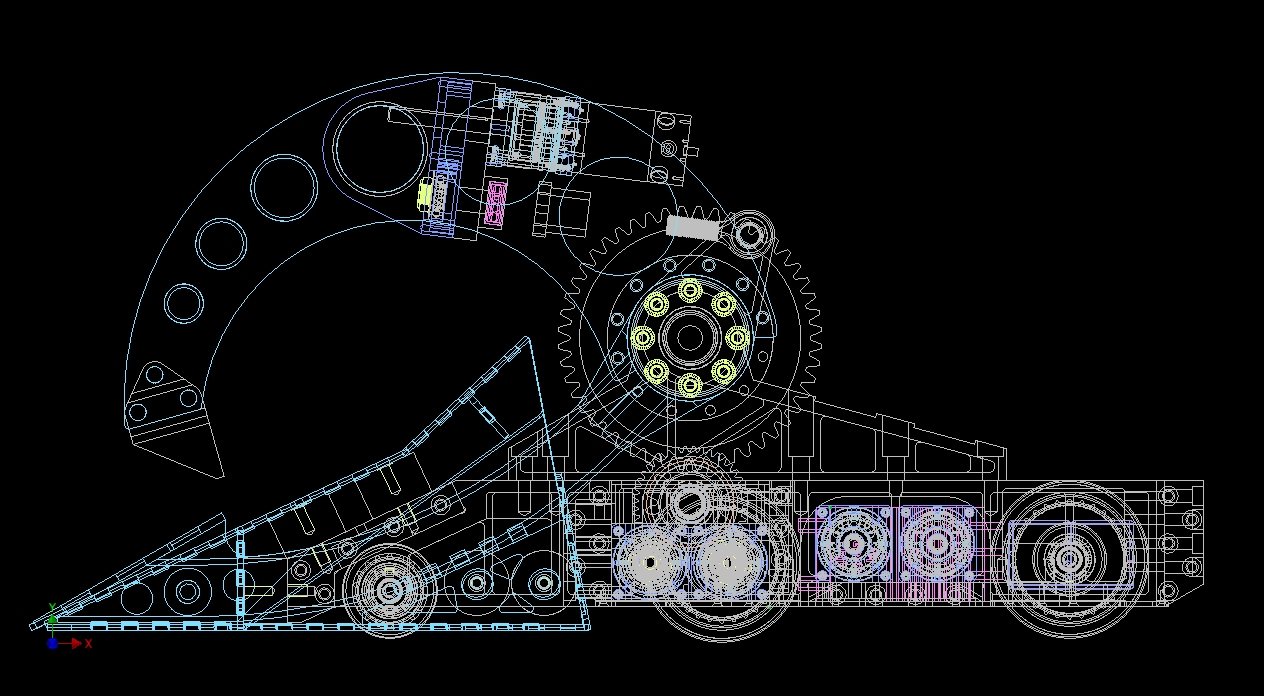
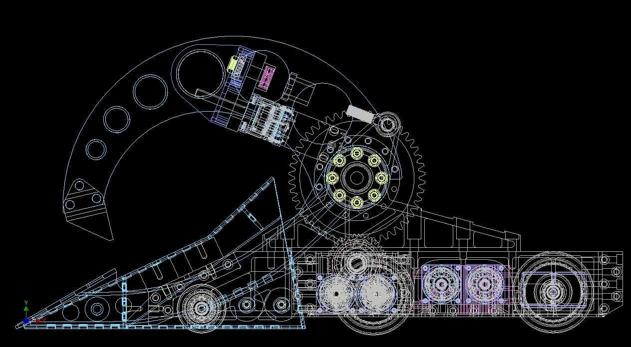
Historically, when I’ve made an electronics enclosure at all in a project, it’s been a constructed (usually t-nut) box made of polycarbonate or some other plastic. So let’s start with what I know. First, here’s the layout and the space I have to work with.

At the time of this design version, the Hobbyking Graphene batteries  had just arrived on the market, and I was eager to try them out. OH2 is not a bot which needs to pull hundreds or even thousands of amps in an instant like a kinetic energy weapon would do, and the new large-capacity Graphene packs (12AH and up) were highly attractive. I designed around the 12Ah 6S packs to begin with. They’re represented with external rough dimensions provided by the HK product page here, in gray. To their left is the final configuration of the DLUX 250A motor controllers after playing with exact spacing.

I decided to start with the “known known” and package the batteries up first. They were going to occupy the only large contiguous space in the back of the bot, which was originally designed to fit four of the Hobbyking Nano-Tech 8Ah packs that OH1 used. These are actually slightly shorter than two of those back-to-back, so I had a little more room to play with.  I made a “minimum dimensional enclosure that’s a clean fraction above the size of the packs”. The enclosure will be made of  1/4″ polycarbonate, likely waterjet-cut, with plenty of my special-sauce t-nut joints holding everything together. This part I’ve done dozens of times, so I left the geometry simple for the time being in order to move onto the rest of the system.

By this time, I had begun receiving lots of parts in the mail, and I began realizing something very distressing – that two Whyachi MS-02 switches were going to be too large to fit. The newest BattleBots rules now require you to have independently-switched weapon and drivetrain power systems. While I had submitted an application showing two Whyachi switches, actually trying to size them in the design showed me that this was mostly ‘last minute homework question’ and practical. Essentially, yes I could fit two MS2 switches, but I would prefer not to.

So naturally, in keeping with the trend for this bot – I designed me own. Gee, can you make touching two wires together scientifically any more complex? Yes, I can.

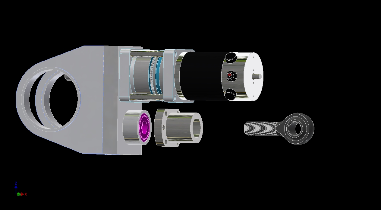
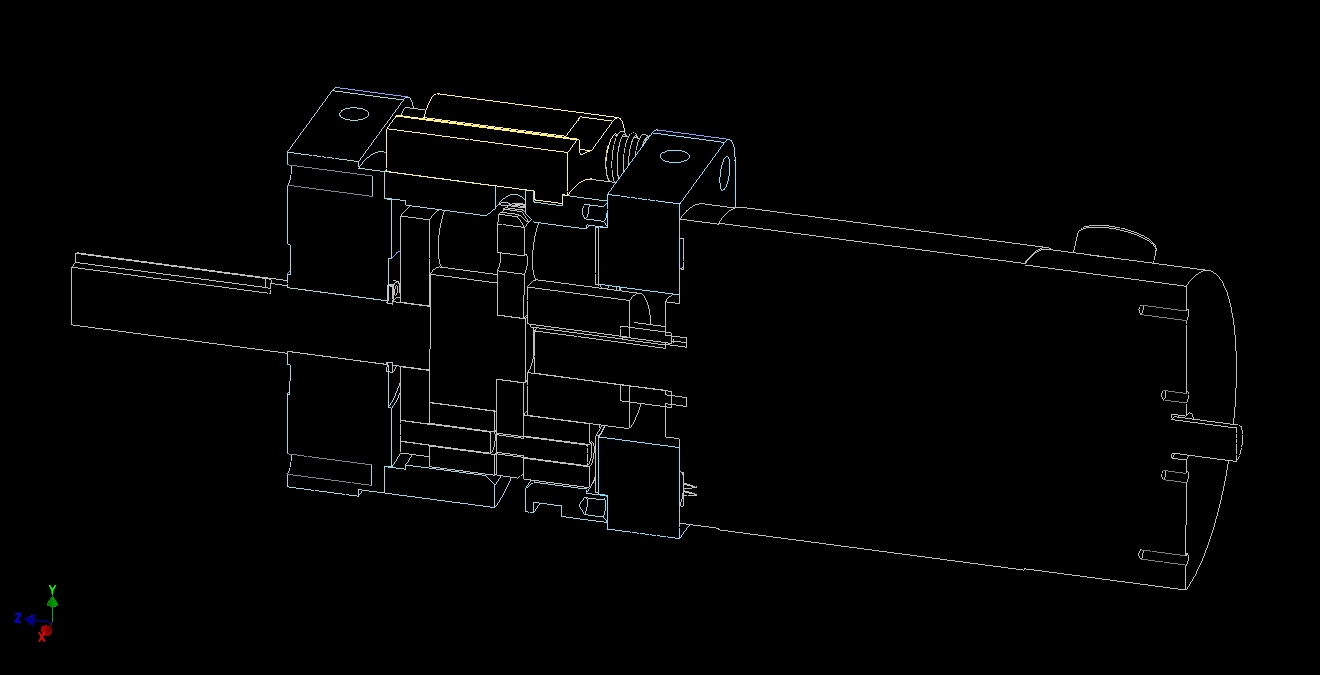
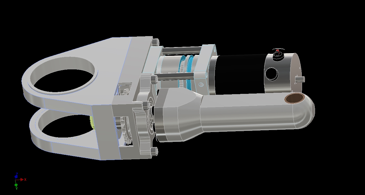
Here’s what’s going on inside that block of nondescript 3D modeling clay. Hint: It’s not much. It’s literally a gigantic Fingertech switch. I designed it such that the square area of the face of the switch (where you crank the contact) is half the size of a Whyachi MS-2, so I could fit two side by side in the space of one MS2. It goes “back” further, but I had that dimension more available.

I didn’t want to get fancy with the contact method, so Fingerth-style “tightening two conductive things onto each other” was the way to go. The terminals are 1/4″ thick copper, and the contact is a 1/2″-13 brass socket head screw. Brass isn’t as conductive as copper, but sheer area makes up for it here – the cross sectional equivalent is a 6 gauge copper wire.

That is revision 1 you see up there. Come build time, I’ll show some updates to this design that make it more refined and less terrifying to use, with the possibility of it being a future Equals Zero product. For now, once again, the shape is set and I can stop thinking about it for a little while.

I’m playing the layout game a little more here, having added a RageBridge 2 to the equation. Instead of “rack mounting” like I am going to do with the DLUX controllers, I decided to lay it flat. The reason behind this was that Rage2 is rather short (heightwise, from the heat sink plate) compared to everything else, and I needed the same area to also be occupied by the switches. If the Rage were also vertical, I’d have needed to push everything sideways, right up to the width between the motors. Leaving some breathing space in a big bot is good for serviceability, the fact that I didn’t want to optimize the design into a corner right away notwithstanding.

I began generating an ESC box in the same manner as the battery box. Check out those big bus rails – that’s how power distribution will be handled. While thinking of ways of avoiding a gigantic tree-root of wires splitting off into smaller wires, I was reminded of the existence of bus bar products after digging through my wiring parts bin and finding some car audio power distribution blocks.

However, most industrial bus bars look like this, which requires putting ring terminals on the controllers. While not the end of the world, I usually prefer the direct wire contact style of the audio distribution blocks. There’s also busbars which look like this, more commonly called ground bars, in the audio power distribution block style. I started shopping around for them, before the realization that they are simply blocks of metal with set screw holes tapped into them hit me.

Well, fine then. Not like I wasn’t going full hipster on everything else electrical already, right? After doing a bit of research on bus bar manufacture, I decided to get some alloy 6101 aluminum from McMaster-Carr and just drill and tap some holes into them. 6101 is the most conductive aluminum alloy in common use for electrical appliances. Aluminum has less conductivity than copper, but you make up for it using more. The equivalent cross section of the bars I modeled is 6 gauge copper wire at the minimum.

The bus bars are offset horizontally from each other by about 1/2″. With another set of holes oriented vertically, it means I can stick a hex wrench through a hole in the top one and land it in the set screw socket of the bottom one. To prevent accidental crowbarring of the circuit (nevermind the fact that the whole bot’s going to be turned off, battery disconnected, and most likely this whole electronics deck removed from the frame when I work on it), the screw access holes will be given little nylon bushings to insulate a passing tool.

The final bus bar design is made from the 6061 bar stock, are 1/2″ x 5/8″ in profile, and about 8″ long each.

Moving on from generating the crude rectangular-box housing to stitching the edges together in my usual style.

Shown also are Anderson 75 amp Powerpoles. It’s a well known fact in the robot world that the 75A Powerpoles are actually capable of substantially more than 75A in bursts. Since I’m not a giant spinning weapon, I needed something which was more substantial than an XT or Deans connector, but to size an actual industrial connector to my load “like 200 or so amps” would make OH2 just one big connector. I brought in two pairs of them to check on the available height for mounting.

In a way, I’m counting on running extremely high voltages to avoid using high current to push power (the alternative being a low voltage system like 18-24v and like all the amps ever).


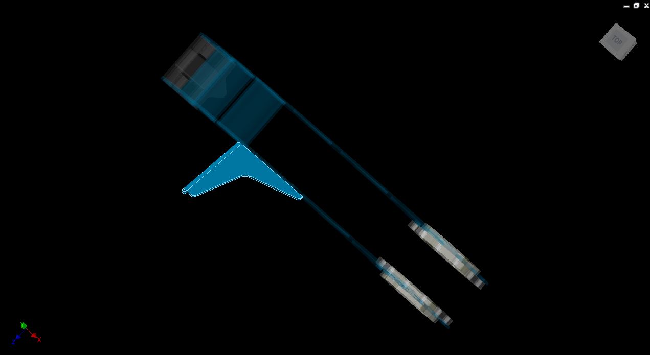
It began being easier to look at in dark wireframe mode – basically Shaded with no shade. Wireframe was too messy, and the transparency of modeling in polycarbonate with default looks meant it was still hard to see the edges. Above, I’ve added the slots for the #4-40 t-nuts.

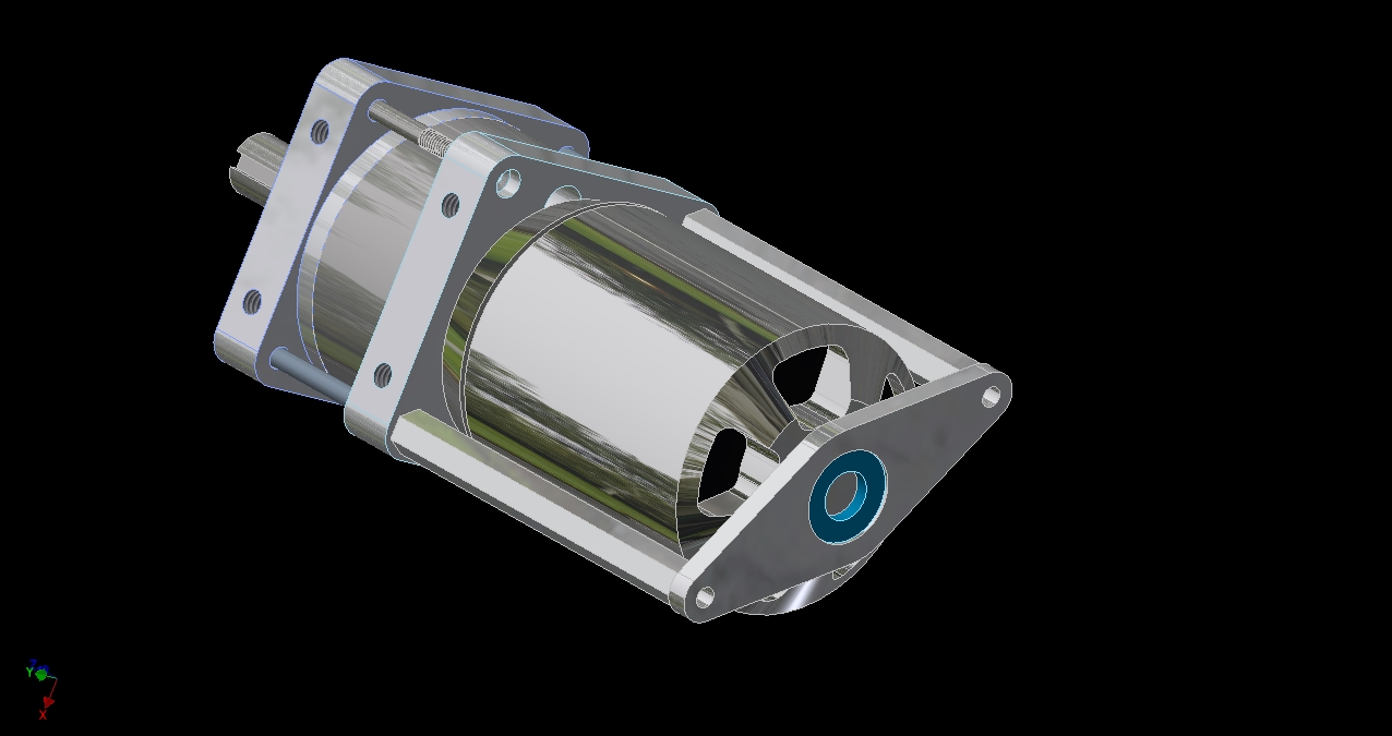
I toyed with the idea of a backplane connector style of battery attachment, where the Powerpoles are mounted to the polycarbonate enclosures, and the whole assembly kind of snaps together and gets bolted in place. I even modeled a 180-degree rotatable Anderson Powerpole mount to do this, seen above.

However, the more I thought about it, the more I wanted electrical connections to be as compliant as possible, not hard-mounted. So, the bot-side electronics enclosure will get this Powerpole mount, but the battery itself will just have a loose connector pigtail.

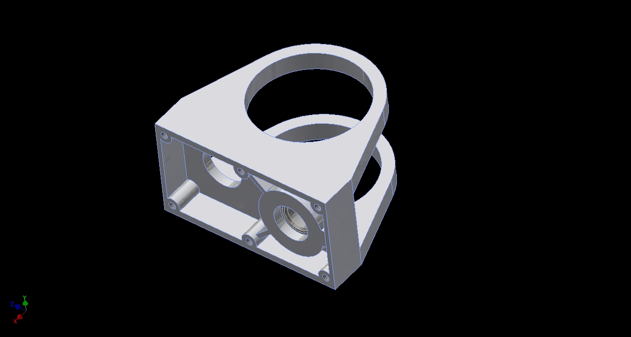
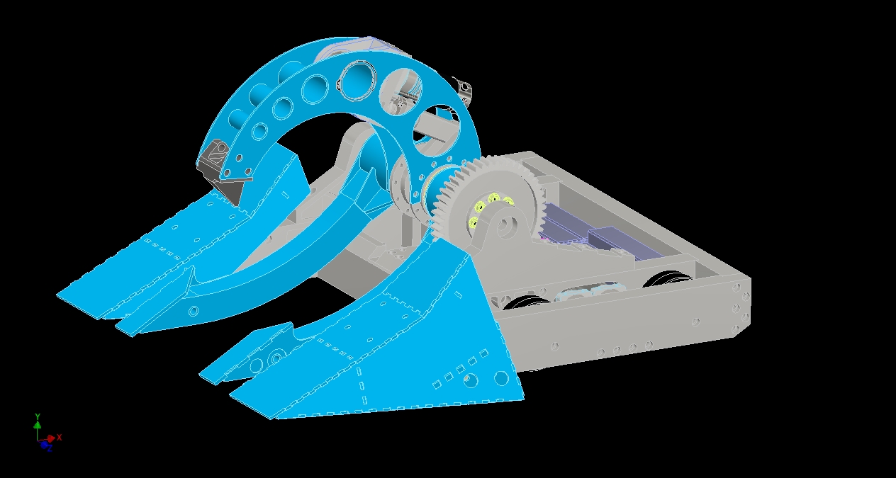
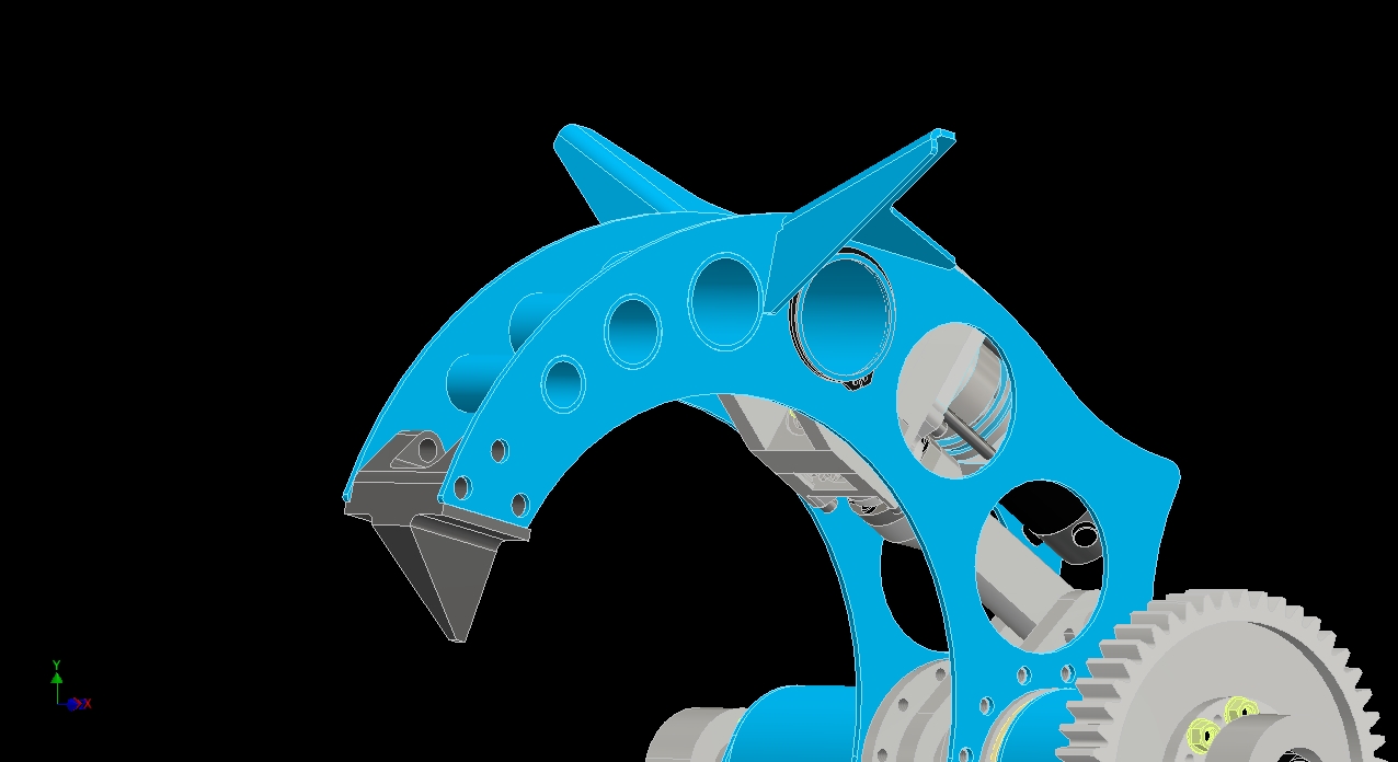
After establishing how big the enclosures were, it was time to flow a bracket around them to hold them in place. This had potential to be the largest part ever printed on a Markforged machine yet, so I was highly tempted.

The premise of this universal bracket was to contain the enclosures using massive areal contact of something mildly compliant (nylon), and also to presenting vertical bolting features to further restrain horizontal planar movement as well as vertical movement.

It also acts an air guide shroud for the drive motors. At this point, I’d been thinking of ways to do forced-air cooling of the whole system, and the holes & vents in the electrical deck were created with that in mind. I was planning on having a central fan somewhere – likely in the empty space to the right of the lift motors and having it pull air through the bot.

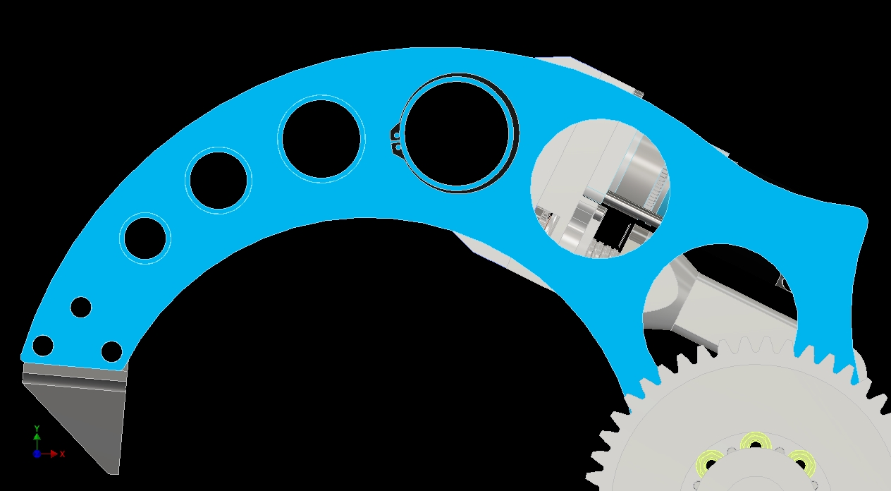
Here is the completed Everything Bracket, with its own mounting features.

I’m now at a point where the whole design is basically “first-pass complete”, meaning I know where everything goes and what it should do, even though it might not be well thought out or optimized. I find that this point is a very helpful one to reach, because the changes you’ll make to the design tend to be evolutionary instead of revolutionary (scrap it and start over). Not to say I haven’t done the latter, but…

In the next episode, I’ll introduce some of the very last CAD kibbles before the real fun starts – the build reports!

The Overhaul 2 Design & Build Series, Part 5: The Top Clamp Arm and Actuator CAD-o-rama

We’re beginning to reach the “minimum entropy point” of the design now, which is the point where I know exactly what needs to get designed and do those in sequence. For me, this usually occurs at the 2/3rds or 3/4ths mark (roughly), when I see the light at the end of the CAD tunnel. Basically, after this, the design sequence will probably get more chaotic as I visit and revisit portions of it.

This post will start where the previous left off, with me beginning to sketch the basic form of Overhaul’s characteristic rounded upper arm.

During the design of OH1, we went through a few arm shapes and construction methods. In large part, the rounded shape was dictated by the desire to avoid bends or miter-welded tube sections to maximize strength, since OH1 at this point was still focused on crushing. We’d already designed the lift arms to be the “tubes and AR400 side plates” method seen again in OH2’s lifting forks, so it was a matter of maximizing strength while minimizing weight.

The arm plates had large circular cutouts to reduce weight without adding stress rising sharp corners, and also looked cool because it was a Preda Raptor knockoff looked like historic machine tool cast iron girder frames. With a bit of reinforcement, that clamp arm turned out to be the most rigid thing on the bot, even without the reinforcing cross-tubes we designed to be welded into the holes.

I wanted to keep the design and look (adding to the visual continuity of the bot) so I started modeling the same way we did for OH1 – with a really big circle. The inner circle is not concentric, rather driven by the radius of the circle forming the hub/attachment portion and the desired tip width. The third constraint in the size of the inner circle was…

…the welded crosstubes. Through some geometry-mancing (geomancing is taken), I came upon a solution for the outer and inner circles which incorporated commonly available sizes of steel tubing that had the holes spaced all roughly the same distance apart. The spacing is not exact, but visually hard to discern the differences. That’s it, I’m keeping this design. It cannot possibly get better from here.

Modeling in the cross tubes. They keep the front portions of the jaw, where the highest compressive forces are seen in an attack, from spreading or buckling. OH1 relied on the tooth joint itself and a sheet of steel that was rolled to match the curvature of the outside of the jaw, welded to the top edges of the side plates.

I quickly modeled a tooth that could be machined from some tool steel in principle, but left it highly unoptimized. I just wanted something visually there to guide the rest of the design, and intended to come back to this later. While I could have this manufacturered, it’s shaped in a way that would require a larger, more expensive block of steel to start with, and also more setups and operations.

The tooth could be used in the ‘hooking in’ direction shown, or it could be turned around. I used the triangular hole pattern specifically for this, since it would keep the design versatile and allow different tooth placements and possible other attachments depending on who I’m facing.

With the top end of the bot visually anchored, it’s time to start thinking about actuation. For starters, I dropped in the “sketch model” actuator I made for the application, which contains a SK3 motor, a P80 gearbox, and some arbitrary solids that may or may not make sense. This allowed me to see how much it didn’t make sense and how porked I was for space, which was very. I spent a while figuring out the best angle to mount the actuator such that it remained serviceable, didn’t stick out too much, and most importantly, could get me the jaw travel I wanted without running into anything else. I’d say the latter two were the most difficult, since the design was anchored substantially in general by the time I got here.

One way to get better actuator placement was to back down on the size of the motor, but that’s for manlets I wanted to retain the high powered grab-or-smash capabilities, especially in conjunction with a very bad idea I began prototyping in November.

After some more design evolution, I’d like to point out the three key features of the new upper clamp actuator. It’s still custom, for a higher force to weight ratio than what I could buy commercially.

First, I decided on a compromise position between the upper “I want to use my motor as landing gear” position where it’s highly exposed unless I gave OH2 a massive steel mohawk, which would be KINDA COOL… or the lower “I want to use my motor to absorb a Tombstone hit” position. The position I chose is in the middle.

This keeps the actuator securely within the two walls of the upper clamp arm. However, it causes a significant bending force to be applied to the leadscrew because it’s pushing off center. The proportion of the bending the leadscrew sees is a ratio between the distance offset from mounting axis (the big hole) to the leadscrew’s axis, and the spacing of the two bearings of the leadscrew (the purple object – there’s another one hidden from view to its left). This meant I had to be careful with OH2’s clamp force calculations, as they could now easily exceed the bending strength of the leadscrew.

Notice also the new motor choice – now an A23-150 Ampflow motor, the “nanoAmp” motor. It’s relatively new to the market, and is roughly the size of a common FIRST Robotics CIM motor, except higher performance. This design change was driven mostly by my desire to exert a constant force on the grabber – something which the “hobby level” brushless systems can’t do yet. I wanted to be able to do this since ball screws are very low friction and will backdrive easily, so if I don’t want to lose grip on someone, I need to keep a bit of power going into the system for holding. It was then not difficult to design around a Ragebridge 2 to use the current-limiting feature, so I couldn’t accidentally bend the actuator.

According to my calculations (… I just used that for real… oh god … oh god) the maximum safe current was about 70 amps using the A23. At this point, the tip of the jaw can push with around 2500 pounds-force. That’s in low gear – in high gear, the leadscrew isn’t a limitation, since the motor can only push around 1000lb-force at stall current and I should not be stalling the A23 at full input voltage unless I was interested in suddenly making a surprise flamethrower.

Obviously not the 6000+ pounds that OH1 was capable of, but we never were able to use it in a match anyway. This new limit would necessitate redefining the mission of the bot; I’d only ‘go for the crush’ if the opponent had armor worth doing that to, such as under 3/16″ mild steel – OH1 managed that at a current of around 80 amps on the F30-150 clamp motor, yielding a force of roughly 5000lb. It managed 1/8″ steel at around 40 amps, which is still within reason for this new actuator.

There are, of course, a slew of unknown factors I have not accounted for – for example, immense friction between the trunnion surfaces could raise the maximum compressive force the clamp can exert before the motor “sees” an excessive bending moment. Or my leadscrews are made from Chinesium instead of induction-hardened E52100 bearing steel. Like I said – every fuckup I might make, right here for you to see, ON TV.

The sound you hear is everyone rushing to make weight for some titanium top armor.

Second (yes, now we get to Second) it uses what would have been one of the large cross-tubes in the upper clamp arm for one of the trunnions. This was a “might as well” type decision – I was going to have to intrude upon the volume of that tube to place the actuator anyway, and so would have had to remove that cross tube from the design. Using the cross tube allows me to still use it for some degree of anti-buckling of the side plates.

Third, wait, what do you mean “high gear and low gear”? (Go back and read the section about My Calculations™) Aren’t P80 gearboxes single speeds?

Not if you are depraved like me. Introducing the “P90X” gearboxconcept:

That is a design for a two-speed, shifting Banebots P80 (with significant modifications). I studied the design of the DeWalt gearboxes and took note of how they accomplished multiple speeds, and duplicated it using the parts of the P80 with some custom machining. In short, the ring gear of a 2-stager is split in half, with one half either forced to be locked to the housing with pins, or spin freely relative to the housing but locked into the first stage gear carrier effectively skipping that stage. Using the 16:1 as a starting point, I can get either 16:1 or 4:1.

This is a project which is basically its own story to tell, so I’ll leave the details of its construction to the later build posts. I’m comfortable with using this idea for now, since if something goes wrong or if it’s unreliable, I can always drop back to a 1-speed normal P80 like a pussy depending on who I might be facing.

Taking the ‘solid block sketch’ of the actuator and making actual features in it now. This part will be carved out of a big aluminum block – a one piece billet trunnion & gearcase. Inside, I’m making features to mount bearings. Using the maximum bending force calculations, it was pretty easy to size some big angular-contact bearings for the job. They require preload, which the ball screws I’m going to get have an adjustment nut for (They’re from the same vendor as the ball screws for OH1).

With some details in, I started placement of the assembly to fine tune external dimensions. This is the “motor high” position now.

And the new “motor low” position. Still not a fan of potentially exposing the motor to a wiggling 250lb opponent, even though it gets me more range of swing on the forks:

As seen here, the “motor high” position current causes the motor to be the hard stop for the fork actuation. To remedy this, I was going to give the clamp arm sides a small extension behind the motor. The “motor high” position causes me to lose around 7.5-10 degrees of possible fork swing. I think I can deal with this.

Moving on to more details! First, I had to reconcile the size of the actuator body with the necessity of mounting things into it. This meant making it ever so slightly wider, to accommodate both case screws and discrete gearbox mounting screws.

I briefly entertained the thought of integrated P80, meaning swapping the gearbox front output plate for an integrated bearing pocket & ring gear holding socket, but decided against it.

In retrospect, I probably should have done this to save some motor mounting volume – it’s not like it’s hard to remove the front plate from a P80 if I had to swap stock gearboxes, and my P90X design could also be accommodated since it simply replaces the center ring gear portion. As long as I was having something super custom machined…

I’ve hollowed the other block to have motor mounting features and the output bearing now. From there, it was cutting away stuff that didn’t have to be there. The openings in the case are to accommodate a larger output sprocket than what otherwise could fit fully inside – I could have made the walls ridiculously thin, but why even bother at that point? Just open the thing up and gain some more sprocket diameter.

Doing it this way let me use a 1.8:1 external reduction to the ball screw, instead of the 1.5:1 I could have gotten at most otherwise.

The last part of the actuator to be designed was the….

ball screw nut shaft

Alright, I said it.

Yeah… that. The discrete rod end bearing (“ball joint”) took up an extra inch of travel for its own mounting threads, so I designed an integrated one. The extra travel gained is worth about 2.75″ of travel at the tip of the tooth due to the leverage ratio.

Test fit of the actuator in the design. Seems legit!

The retaining method for the trunnion tube, a 2.75″ OD steel DOM tube, is a Giant Snap Ring. Also note the small mini-mohawk that I gave to the upper clamp side plates. This extends about 1/4″ past the motor and will hit the top plate first. The tip radius there is fit to weld a section of 3/4″ OD steel tubing over for more robust contact area – I’ll determine the need for this “dynamically” later on.

Time for a brief aside from actuator and clampy-jiggy modeling. I’ve been thinking of ways to retain the rotating shell of the SK3 motors since starting the project, but always put it off. It’s essential that this gets supported, because otherwise, the whole spinning mass of the big outer rotor is being supported by a little aluminum stick in the middle. A China-luminum stick. That’s just asking for an impact to break the whole motor off.

#nope

So, two of the P80 mounting screws get extended another 10mm (using 50mm instead of 40mm cap screws, for instance), and hex standoffs get screws onto the extended studs. A little plate with a flanged bearing sits at the end of the standoffs, and the flanged bearing rides on the 10mm shaft nub on the back of the SK3. Self-contained and rearrangeable.

Back to clampy-thing!

The next step is modeling Overhaul’s characteristic self-righting ears. Everyone seems to think they were decorative, but they were vital to OH1 being able to self-right.

Überclocker, for instance, is short enough with the fork and clamp down to fall onto its back, from where I can swing the forks up for quick righting. The curved upper arm of OH1 (and OH2) means the tilted upside-down position, where the bot is roughly at 45 degrees rolled over, is stable. This is bad. We discovered 3 days before ship that OH1 could not get out of this position in any way.

The ears were added to artificially shift where the stability point was, such that with some arm movement downwards, we could guarantee the bot falling onto its back, and then being able to push upwards and over. OH2 should be able to “dynamically self-right” easily due to the sheer speed of the fork, but better to have insurance.

I decided to make the ears one-piece from a bent steel plate for easier fabrication. The weldment would use two points on the upper curve and then a tangent to one of the cross tubes for alignment. All-around, better than the freehanded triangles of the OH1 ears.

Cutting out a few ounces where it wasn’t needed to support the weight.

And here we have them attached to the upper clamp arm.

The shape and extents of the ears are not settled. In fact, they will NOT be settled, made, and attached until we get OH2 together for a self-righting test. By Inventor’s center of gravity calculations, this shape should work in most arm-down positions. But real life testing will be needed to validate this part.

Up next: Electronics, electronics, and more electronics. As a mechanical engineer, I am obligated by oath to leave “the electrical stuff” for last!