The Successor to Melonscooter

Ah, Melonscooter.

The unsung hero of my vehicle fleet, it’s the one that actually works most of the time and which putzes me back and forth day to day. It’s a mish-mash of unmatched parts and on-the-spot engineering built on top of a scrapped commercial scooter frame, which has been operational with only a few small service gaps since 2010. Like any vehicle that is more tool than project, it’s also been slowly backsliding partswise as things wear out and I replace it with whatever the hell I happened to have within arm’s reach. For instance, this past few months has seen it devolve from the melon (C80 motor) to an SK3 59mm motor as I realized the bearings on the Melon were slowly becoming powder:

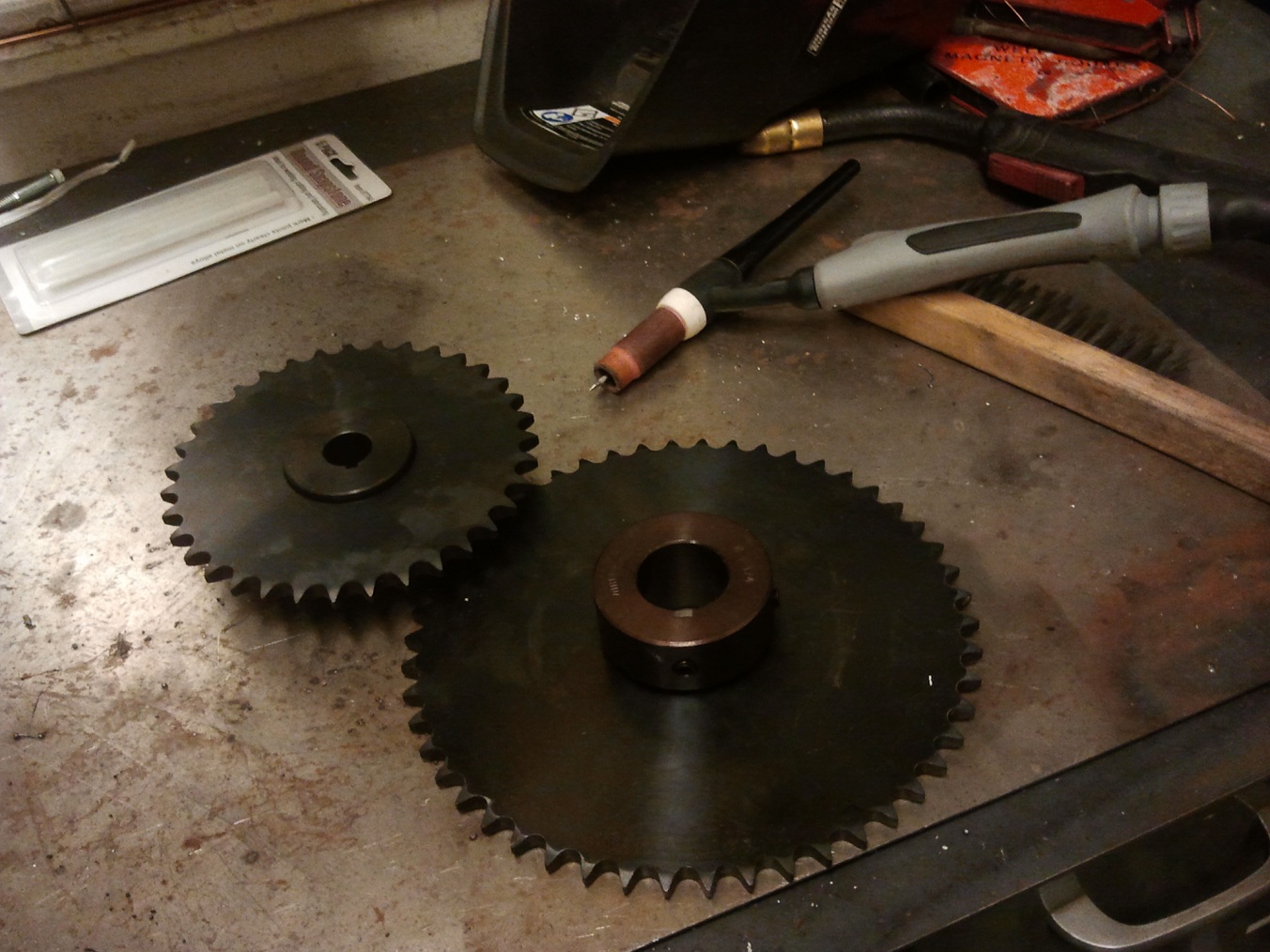
Then, one day in February while pushing through leftover snow, the timing belt disintegrated again – Melonscooter has never seen very good belt life due to me using the HTD belts at way above their safe rated power – and this time I had no spares. So naturally, I devolve even further to chain drive:

The wheel and chain were spare items purchased for that term’s 2.00gokart class.

About the same time, the front of the frame near the steering neck broke a weld and developed a crack. I rode it like this for a while, being extra careful to not put too much load on the joint, and eventually welded it back.

Sadly, Melonscooter finally succumbed to a combination of poor Chinese metallurgy, years of New England road salt, and probably my welding. One day in May, I thought the ride was getting a bit jiggly for some reason. As I pulled onto a sidewalk to investigate, this happened:

Well then. This isn’t very productive.

I’ve been swearing to rebuild Melonscooter on and off for the past year or more, but like a certain other somewhat rusty vehicle is now, it’s just continued working. The entire joint area appeared to have rusted out – I didn’t see it only because it was well covered in paint. The failure propagated clearly from a crack (though not through where I welded).

By this point, the top plate was also cracking from sun exposure, the headset bearings had lost their cages and shields, and I already had another giant hole in the battery box (from going over some sidewalk too excitedly a long time ago) which was becoming its own rust problem.

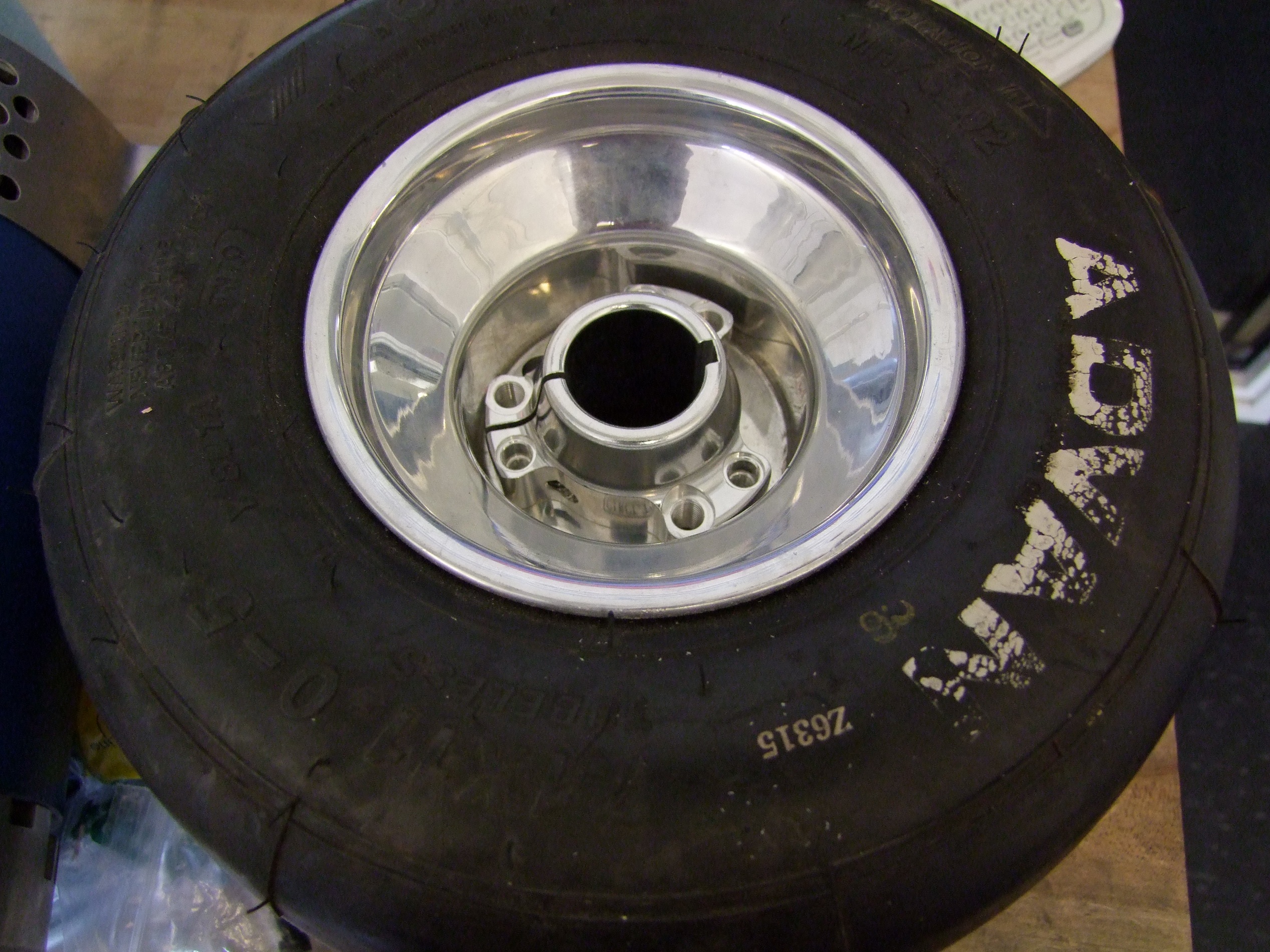
So I took this as a sign that I needed to move on. While 2.00gokart was wrapping up, I haunted the ever-powerful Craigslist for a cheap donor scooter, electric or otherwise. A week later, I found this thing:

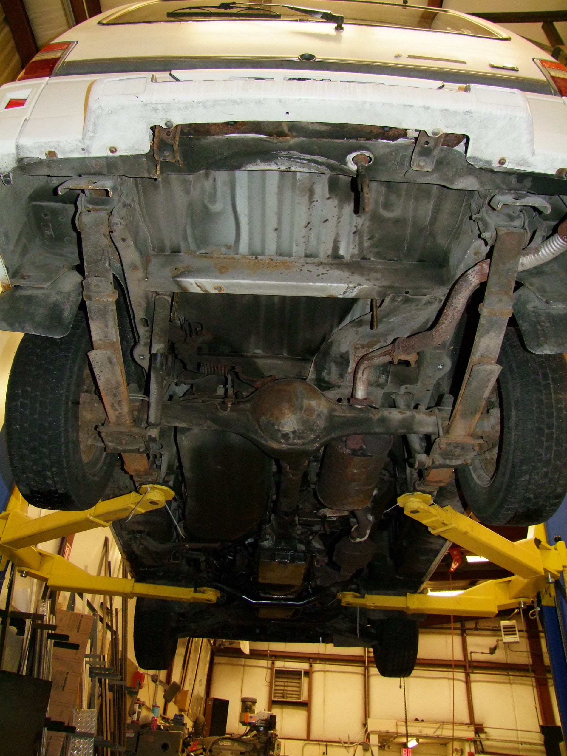
What is it?! A blurry dark picture in someone’s garage and the tagline “scooter $50” or something to that effect led me, on one of the very first long-distance Mikuvan missions, to this thing. It’s an “X-treme XG-505“, which demonstrates that convoluted alphanumeric naming is not exclusive to the domain of motorcycle manufacturers. Either way, it’s beefy as hell – the steering neck joint on this thing will clearly never fail in the same way. The giant deck is solid 3/16″ aluminum, and the frame is 1/8″ steel plates and what looks like .075 wall steel tubing. It also has dual disk brakes.

Basically, a great (if huge) candidate for chopping up. It was also not running, with engine trouble.

This sounded entirely too familiar, so at the risk of betraying my electric brotherhood, I immediately began tearing the engine off and stripping the frame, readying it for electrification appraisal.

While tearing down the electrical system consisting of a starter battery and related circuitry, I discovered the world that is scooter starting solenoids. They’re basically miniature contactors (slash high current relays), and could be useful if you need something between a 30-40A automotive relay and a 300+A full size contactor.

Starting solenoid also means electric start. What I also found is that the 49-50cc engine kingdom can be found with electric starts that are pretty damn cool – 4 brushed, neodymium magnets, basically like tiny Magmotors Ampflows. The downside is they are often shaftless, being designed to mate to the engine crankshaft.

Still, I do want to mess with these and see what they’re capable of.  I was going to tear this engine down further to extract the electric start, but someone else already called dibs on it so I didn’t want to leave it permanently disfigured.

If you want to mess with these parts, I’ve basically found then using combinations of search terms like “49cc 50cc electric start” or “49cc 50cc solenoid” or similar.

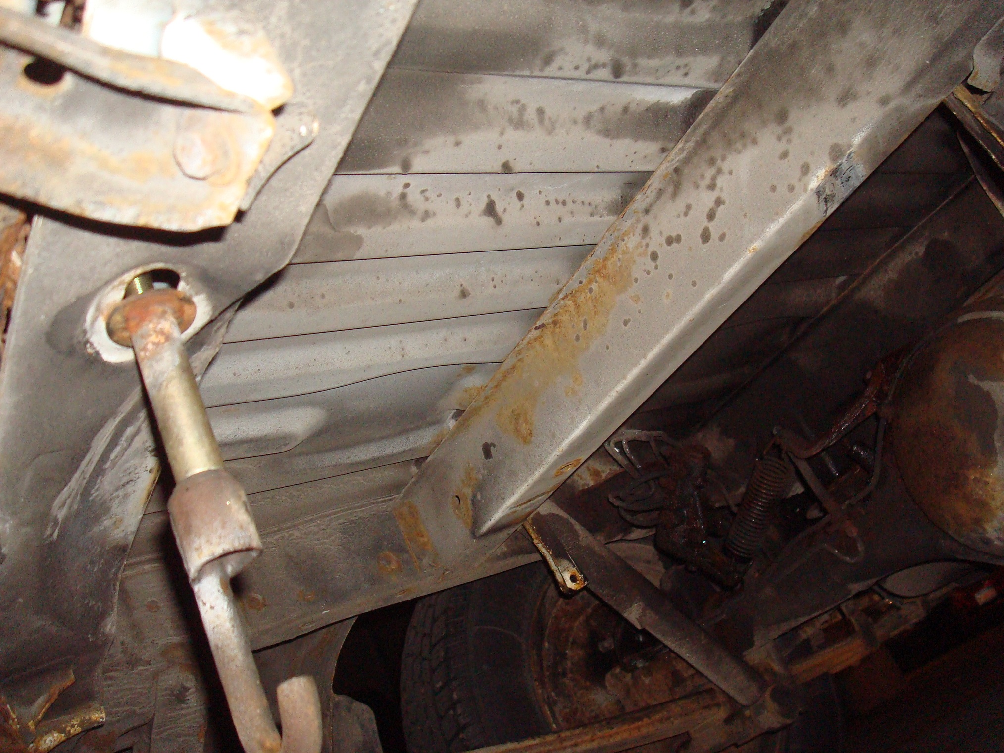
The teardown continues! Did I mention this thing is enormous? The wheelbase is a good 4 or 5 inches longer than melonscooter, which is already pretty long to begin with. If I want it to fit in the same places as before, I’ll need to do some creative basket mounting. I am, of course, designing a basket into this one from the very start.

The last thing to do before I could crack my CAD knuckles was to remove the engine mount. This was done with some selective angle grinding. The engine mount actually stuck through on both sides of the deck’s rear portion; the part on the bottom I couldn’t reach with a cutting wheel, so I literally had to grind the entire thing down to flat – as the result photo shows.

With the ugly metal pectoral fin gone, I began to size up the new “stern deck”, characteristic of Melonscooter, that would also mount the motor and be a splash guard and milk crate holder. The frame’s rear forks are just vertical 1/8″ steel plates with a flat plate in between, but it was very much the wrong width to reuse the old aluminum one from Melonscooter.

While it would have been simple enough to remake the aluminum deck in the correct width, I decided to make a bent sheet metal housing instead. I figured as long as I was most likely going to need to make sheet metal structures for a certain future electric derpy van (temporary or otherwise), I should get some practice. Fast forward to after I was completely done with being occupied by 2.00gokart:

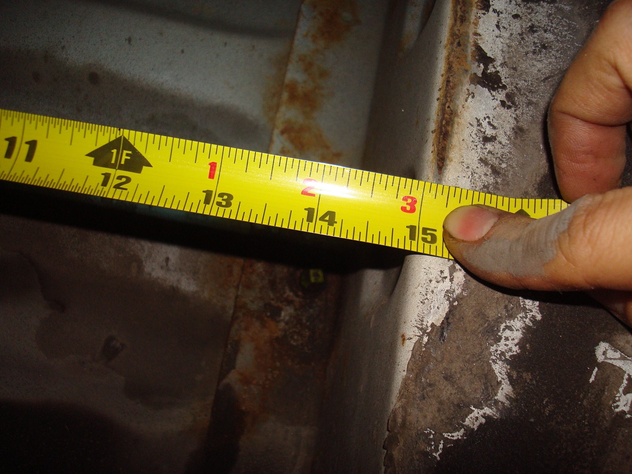
I hopped into the Inventor sheet metal mini-game and, using some crude measurements made with a tape measure and straightedges, whipped up this protoform stern deck. Now, when I say sheet metal, I actually meant 12 gauge (0.1″) steel.  Yes, this is some serious sheet metal. It is, however, the same thickness as the rest of the plate steel on this frame, there’s no additional frame that will be on the underside (e.g. it’s entirely structural), and there could be a few dozen pounds bouncing in a milk crate suspended off the back sooner or layer, so it not only had to be structural to mount the motor, but also rigid in bending as a result.

I think I could have gotten away with 16 gauge (roughly .060), but my intuition is calibrated to working with aluminum and I sure as hell wasn’t going to put 1/16″ aluminum in this application. And I had a 24 x 24 plate of it already chilling in the shop. The other reason was that I could easily mock this up with some 0.1″ thick paperboard stock I also had. This was someone’s laser cutter feedstock, but they left an entire 3 x 2 foot panel of the stuff in the lab.

So using my crude measurement model, I made a paper version and tried it on the frame:

This crude-model-to-cheesy-prototype stage showed me what dimensions were sane, what needed a little bit of changing, and what was totally off base. It turned out the major dimensions were reasonable, so I only had to adjust here and there for looks and clearances.

Back to the CAD world to add mounting features for the motor. The two holes up top are for an eventual basket clamp I have in mind. Those ventilation grates will make sure some airflow is directed over the motor, so it’s not just spinning inside a hollow box.

This little piece adds some more rigidity to the very rear of the deck and also functions as the other component of my eventual basket lock.

Adding some lightening to the other side of the deck which doesn’t need to hold the motor. All of this will be waterjet cut, bent into shape, and then welded.

Like so. Notice the additional slots and edge nibbles that are on the folding edges. Inventor automatically “unfolds” the metal to a 2D cuttable form for me, but I wanted an easier time bending the steel, so I added the slots right on the edge of where the bend is supposed to start to “encourage” the metal there. The triangular nibbles tell me to align them exactly with the teeth of the bending brake.

I used the Giant Brake of Certain Tibial Fracturing in the FSAE/Solar Car machine shop to push this metal around. The machine is pretty clapped out and uneven, so I stuck to one side as best as possible. If I find myself needing more intense sheet metal fab, I might take a stab at repairing this thing too. For now, push-lever-metal-go-bendy is enough.

And the final piece fitted onto the rear with some clear tape. I accidentally left the teeth too far away from the edge of the brake for the last fold – the one with the grille on it. That’s why it’s inset a little from the edge of the side flanges. Fortunately, it was not a disastrous mistake.

Up next: Actually welding this sucker to the frame, and where the hell am I going to put the batteries? To also feature an extensive DERPDRIVE update, since it, too, involves tons of metallic hot gluing.

A Mikuvan Subproject: Operation DERPDrive

I’m going to take a quick break from being too sissy to start on rust repair work to begin a thread for something which has been planned since the beginning when I got the damn thing. As I keep telling myself (I swear this is still true), the end goal of this project is to fully electrify Mikuvan with a Siemens 1PV5135 motor, Azure Dynamics DMOC645 inverter, and a stack o’ batteries from everyone’s favorite undead alphanumeric battery company. When I bought the van in non-running condition, this seemed like an immediate possibility; at the time, neither I nor anyone on the trip were auto mechanics, just your average Battlebots-buildin’, scooter-ridin’ hoodrats.

Well, now that it’s running just fine for some reason, that enthusiasm has been admittedly damped a bit. Taking it out of commission now to drop the engine and transmission out would mean potentially months of MITERS no longer being able to haul hundreds of pounds of shelving and materials on a whim:

We can’t have that, now, can we. But I’m a little too heavily invested parts-wise in this project to never let it see the light of day.

Here’s the trouble: There is a gap of about 1 mile between the shop with a 2-post lift and my actual, legitimate parking spot for this thing, with a rather steep garage entrance ramp in between. I can’t hog the lift or the patch of space underneath it for months on end while working it, and I would hate to ask for a tow or push from someone else every time it needs to move. If electrification started in earnest, there will definitely be a period of time when the vehicle will have absolutely no remote possibility of moving under its own power.

From the start, I pondered ways to real quick rig up a temporary electric drivetrain that could exist wholly independently of the vehicle and basically jam itself under it to move it gingerly around. Ideas were thrown around ranging from what basically amounted to a two-man push-assist made with welding wheelchair motors onto a stick, to hijacking the rear driveshaft directly and basically going parallel-hybrid. At times, the thought of seriously manufacturing a “car tractor”, like a smaller aircraft tug, marketed towards shops and yards was considered.

What I didn’t want it to become was a science project of its own. It had to be quick and dirty, existing just to scoot Mikuvan in the dark of night between shop and spot. It could move at 5mph for all I care – it had to go all of 1 mile, but it had to have enough torque to shove the whole thing up a roughly 20 degree slope.

parts

I consulted the low-orbiting cruft cloud that is the N5x complex and came up with a few candidates for this job.

  • Basically gluing a power wheelchair to it. 10″ wheels, 24v motors upped to 36 volts, and basically 5 miles per hour it was. I had my doubts that the motors would even have enough thermal load capacity to make it that mile. It would definitely be easy. The downside? Not even theoretically enough torque to push the thing up the entrance ramp to my parking garage, and I won’t be able to get enough speed out of them to take a run at it either.
  • Eteks everywhere. Between all the electric vehicle shenanigan hotspots, there must be like five brushless Eteks (now known as Motenergy ME0907s). One would have been more than enough power, but it would require external gearing (slash chain drive). I also don’t have a brushless controller big enough to make this worthwhile.
  • Cap Kart-Van hybrid. The giant D&D sepex motor (Hey guys, how fucking hard is it to give me one damned web catalog with all your motors on it? What is this, 1993?) of the legendary Cap Kart was dismounted a while ago to be used as a dynamometer load by someone that said something about solar cars. Like the fate of many projects at MIT, it never got remounted, and has been sitting on a bench since. This thing, a D&D ES-101A-33 type, is pretty much capable of moving a Geo Metro or something independently, with a peak power capability probably north of 20kW.

Controllerwise, I mined up a working Alltrax DCX500 from the defunct Vehicle Design Summit group, whose materials have been slowly diffusing back into the building’s various tenants. Running at 48v and up to 500 amps and paired with the D&D motor would make a respectable power system on its own – and certainly one hell of an pushing attachment. Parallel hybrid is looking reeeeeal good right now. Needless to say, this combination, with its appeal to my sense of unnecessary overkill and having just the right amount of potential disaster, won the appraisal round handily. The power source would be taken care of by one of the prospective alphanumeric battery modules – we’re not talking Model S class driving range here.

I also scavenged back from MITERS one of my old 11″ (real) go-kart wheels which was going to make it onto the never-built Super LOLrioKart back in the day. At this rate, I might as well just hang Cap Kart, whose carcass is hiding in a corner, off the tailgate and be done with it.

I ran some quick numbers and found that the D&D motor would only have needed around 4:1 of gearing to shove Mikuvan straight out of the garage while pulling 500 amps. Unfortunately this would have also resulted in a go-kart-like speed of about 45mph once I was done with exiting. Appealing, but I would also like to avoid piloting something without power steering or braking at those speeds. An 8:1 reduction would cut the speed to around 25mph with the ability, given enough traction, of shoving Mikuvan straight up a wall. Now, 25mph is plenty to keep up with traffic and have nobody notice that something might be a tad off.

placement

The next question was where to put this complication. For that, I turned to the underside where my spare tire was hiding:

Emphasis on was – the spare tire was basically the first thing I removed and disposed of since the rim was almost completely rusted out. Dismounting the tire and hanger uncovered this pristine area between two parallel frame rails in the back – the “#6 Cross member” and “Rear End Cross Member” according to the manual. These things are (as it turns out) monocoque construction but with a discrete frame structure, so it’s not totally unibody like modern minivans tend to be.

Here’s a better look from under the lift:

(It’s also the only spot on the underside that isn’t covered in filth.)

This spot seemed to be begging for a weird action movie attachment to be installed in it. It’s located very close to the rear axle, so I wouldn’t need to build in tons of compliance and “suspension” travel. It’s out of the way of the possible design and manufacturing exercise up front. And parallel frame rails.

The only downside I could see was that I might want to hide the Siemens motor in that spot some day, but I think by that point I’ll have a justifiable reason to leave it on the lift for a little while. That, or give it a nosewheel.

The dimensions were also pretty handsome:

The width between the rails was 15″, with another 10″ ahead of that before the rear differential bulb. The rail depth was about 3″ and the distance from the underside of the floorpan to the ground, with the vehicle parked on a level surface, is 18″. Width was pretty much arbitrary.

the mechanism

I spent a while musing about what kind of mechanism to mount everything with, and how to attach it to the frame. I didn’t want to weld anything in (making it permanent, at least from my traditionally welding-free building methods), and wanted to avoid drilling and bolting if at all possible.

Not knowing how strong the spot welds holding everything together actually are, I decided to pursue a jacking type of attachment. The structure of this device would push itself against the two frame rails hopefully with enough strength to resist the loads of the motor cranking on it. This was going to have to be a very strongly braced connection, since I’m basically mounting a fetal twin EV to the underside.

If it turned out that I was going to pop welds or bend sheet metal, I would just bail out to drilling and bolting using blind insert rivet nuts into the frame rails.

I began by hopping into Inventor and sketching out what would basically be going on:

I made the basic mechanism in a sketch, first using lines only (or just the essential “bones” of the mechanism), then fattening it up with representative motors and wheels. In this graphic, the big circle is the 11″ go-kart wheel and the smaller circle is the D&D motor.

At this point I’d basically settled on making most of this contraption from welded steel tubing. My usual modus faciendi is to waterjet-cut some plates and throw them together, but I’m guessing that the majority of fabrication on the final vehicle – motor mounts, battery boxes, additional structures, etc. – will be welded, manipulated steel sheet and plate joined to tubing, so what better than to practice?

The mechanism of raising and lowering is an extremely simple single-swingarm, almost like a motorcycle rear end, with what would be a “shock absorber” in a real vehicle application being an adjustable leadscrew. That way I can crank the wheel down and continue loading it against the ground to take weight off the rear axle.

And this mechanism in the lowered position.

With the basic mechanism loaded in my head, I started embodying it in 3D. This is the tube structure that will be welded up. 2″ square tube make up the swingarm, 1″ square and 1×3 rectangular make up the framework. All 1/8″ and 0.1″ wall – in other words, 1,000x more heavy duty than the van itself. I’m fine with that – this shit is cheap.

Using the 2D sketch mechanism info, I transferred mounting holes to the 3D model. The four holes are mounts for some beefy pillow blocks to hold the wheel driveshaft and the intermediate shaft needed to complete the 8:1 mechanism in two stages (I can’t achieve that in 1 stage without going to ridiculous sprocket sizes)

I’ve moved onto adding models of the D&D motor and wheel. The dimensions are obtained from calipering the real world items.

Added pillow block models and also one idea for performing the frame jacking. The pillow blocks are giant cast iron jobs from Surplus Center – maximum cheapness per bearing.

The jacks are giant turnbuckles used in reverse to provide compression force. But wait, aren’t turnbuckles only designed to add tension to a system? Yes, hence the hugeness. The long skinny sides of turnbuckles make them ill-suited to pushing against a load – they’d rather buckle apart. I figured that making them enormous would mitigate this issue for the clamping forces I’d need. These are 10,000 lb turnbuckles from McMaster, who fortunately pried a CAD model from the legacy U.S. company that is making them so I did not have to drop $70 to find out otherwise.

I wasn’t too set on the returnbuckle idea, but for the time being I settled on the rest of the mechanism and assumed a jacking method will exist.

Turning my attention to the leadscrew linkage, here’s some shots of the trunion design. The trunions will be made of some chopped up 1.5″ diameter steel tubing with welded endcaps. The nut in the center there is a standard 3/4″ Acme steel nut, the kind you use to hold steam valves together, and again purchasable on Surplus Center for a guava and two potatoes.

The underside is where it gets a little interesting. So here’s what’s going on – As the wheel contacts the ground, the blue spring will compress with every further turn of the leadscrew, adding “preload force” down on the wheel. If the wheel hits a pothole or something, or I drive off the entrance ramp, it can dip town and maintain traction, avoiding awkward fake burnouts.

If I need to crank the wheel back up, then the J-shaped hook applies pressure to the backside of the swingarm trunion (the long round tube in the center) and so the whole assembly can float back up. When the spring is compressed, the hook moves away from the trunion a little.

What this doesn’t do is add upwards compliance, say a speed bump or armadillo in the road (because Cambridge has a wild armadillo infestation issue – ask any long time resident). However, the path I intend to take is pretty free of obtuse bumps. If the wheel hits an obtuse obstacle, the forces should be transmitted handily into the ladder frame. Should be. Those insert nuts are looking delicious right about now.

I knew coming back to the previously handwaved mechanism would make me smack myself for even thinking of it. Here is a new jack design made only of welded tube, threaded rod, and nuts. $150 cheaper and probably less shady. The forward (right side in the image) bar is free to move in and out of the tubes, kept from moving in only by the two nuts jamming against the tubes. If I need to expand the width, then I just crank on the two nuts.

This design was frozen after a few days of not looking at it, during which I instead watched the Singaporean students try to design kart drivetrains using 4,000 RPM/V motors. Which, mind you, is totally possible if you don’t mind using a 100:1 gearbox or something, but your handling could suffer.

construction begin

Here’s the pile of big parts as of last week. Motor, sprockets, bearings, a bunch of related hardware…

…and this pile of steel, primarily foraged but also ordered from Speedy Metals. The huge shafting, in 3/4″ and 1 1/4″ sizes, came from Surplus Center to match the bearings.

Why such huge shafting? It’s because as it turns out, 1 1/4″ is a standard American go-kart wheel axle diameter. I found a cheap hub on eBay which matched the wheel perfectly and converted it to a 1 1/4″ shaft.

I’m guessing the 32mm standard size is the Irritatingly Close But No metric size for the same application.

I also tried something a little different sprocket-wise this time. I normally waterjet my own sprocket profiles, but with the assemble-from-COTS-parts mantra of this build, adapting them to the drive shafting would have meant that custom flat plate sprockets were pointless. Instead, why not buy commercial flat plate sprockets? From Surplus Center, large sprockets get cheaper as you move to these “welded hub” versions. For $20, you can basically have any sprocket size and hub bore/feature combination. The final output sprocket, of 50 teeth, gets the huge 1 1/4″ keyed bore, and the smaller intermediate sprocket will ride on a 3/4″ keyed shaft.

I’m going to spare the welders the pain of seeing my handiwork, but let’s just say that “MIG-over-TIG” was an acceptable ditch plan. It’s often said that in TIG welding, the best welds look like a stack of coins. Mine look somewhere closer to a stack of rabbit droppings (Part of the problem, as I remembered/was reminded, was that I was trying to weld these sections using a 100 amp TIG welder and a tungsten too small to even take that current).

With the parts buffered and ready, it’s time to attack the structure itself. There’s much welding metallic gluing ahead; the next post will focus on the construction of the structure and machining all the little round things that go into it.

In typical fashion, I spent a few minutes thinking of ways to name it as close to an Internet meme as possible, and the result is Detachable Electric Rear Powerdrive , or DERPDrive for short. I wish everyone the best while facepalming.

Also, I found a nice sample of first Legendary Derpy Van, the Toyota Van, while cruising through Cambridge back streets avoiding traffic one day. If only vans were like dogs or guinea pigs.