Cold Arbor is reaching that point in a build where another day of work will suddenly make a pile of parts appear cohesive and robot-like. Most of the fine details of the two linear actuators have been addressed, and I’m almost ready to move onto making the saw assembly itself.
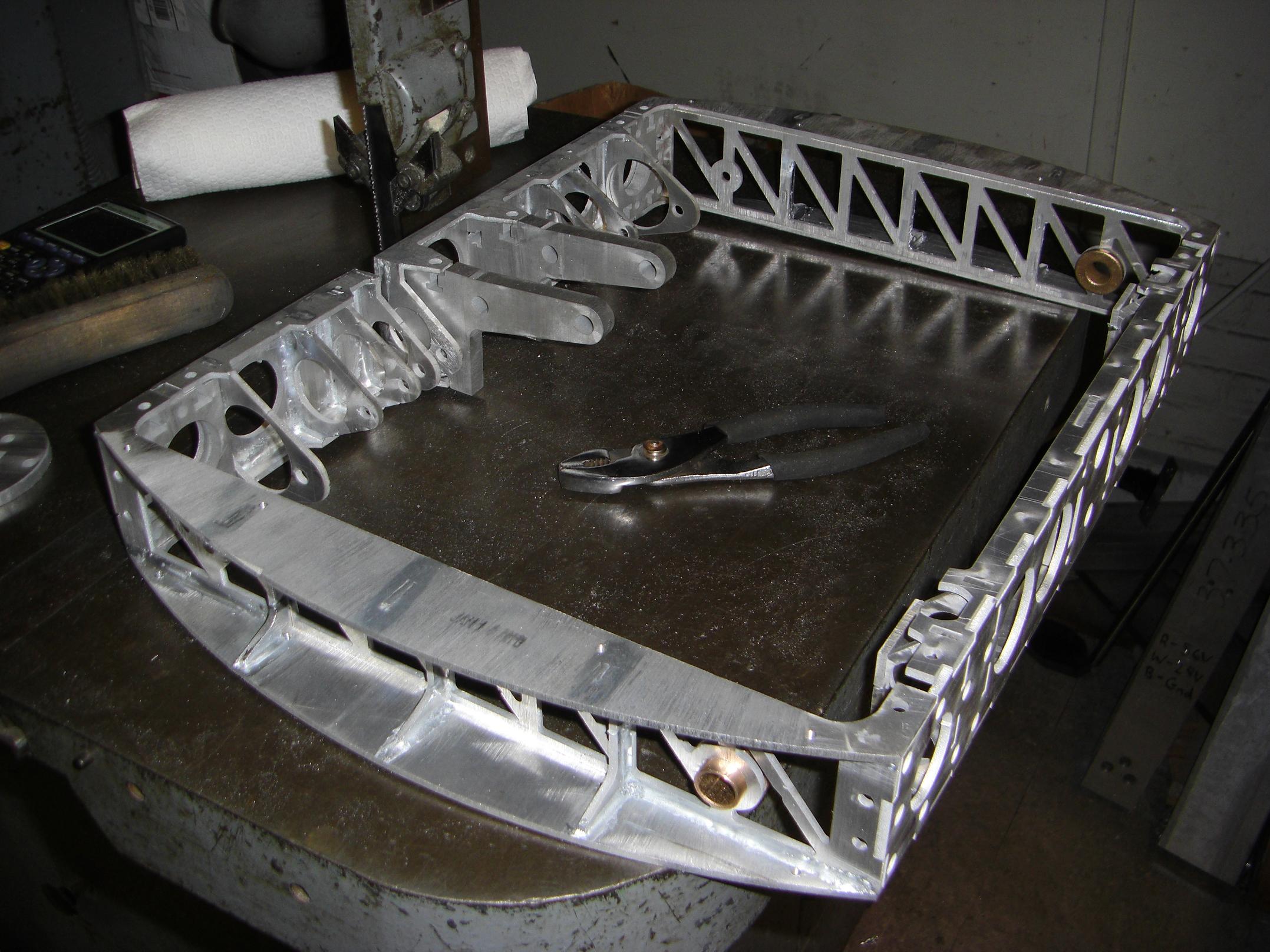
Additionally, I’ve had the chance to cut out more parts and put the entire frame together.
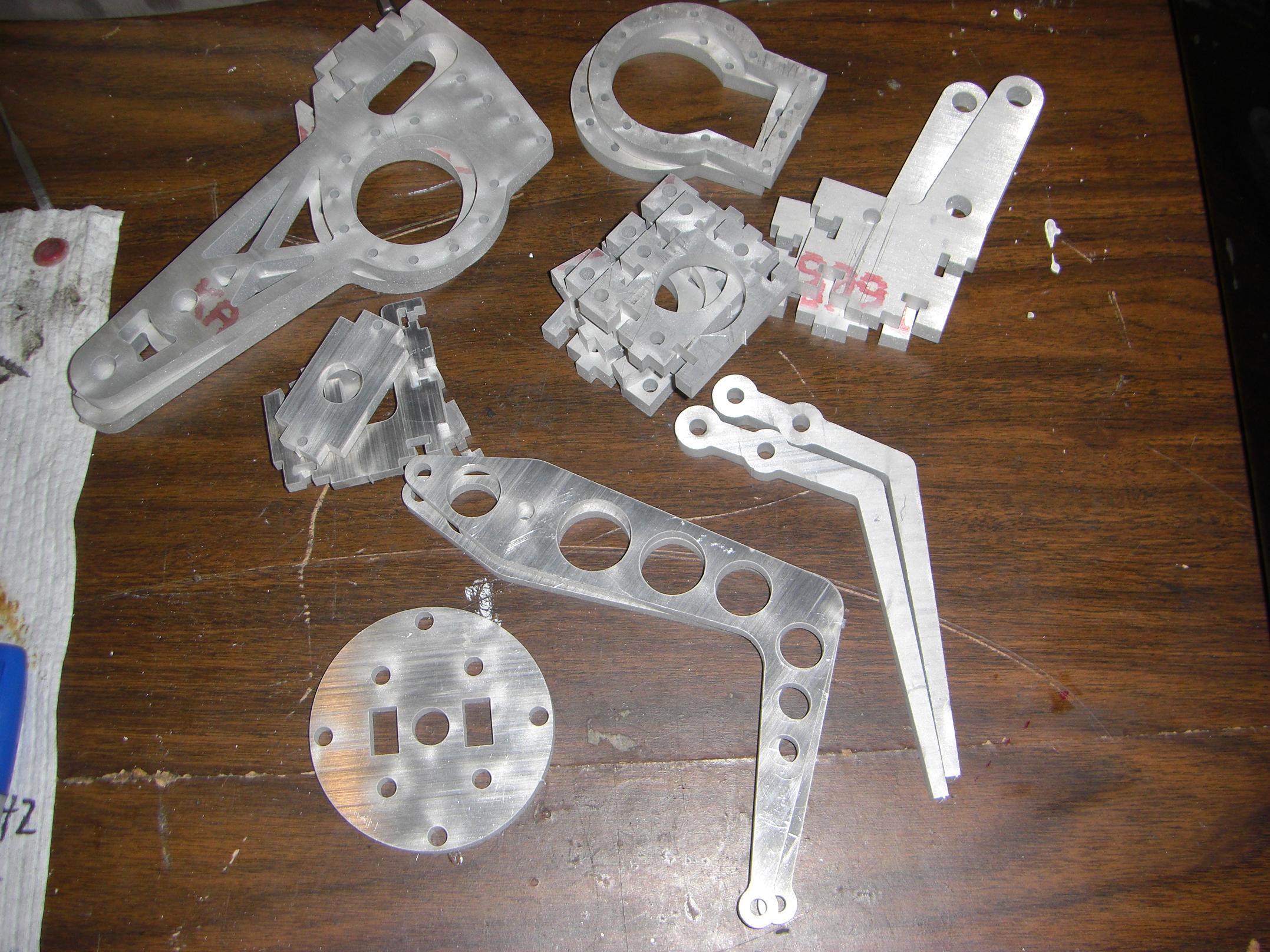
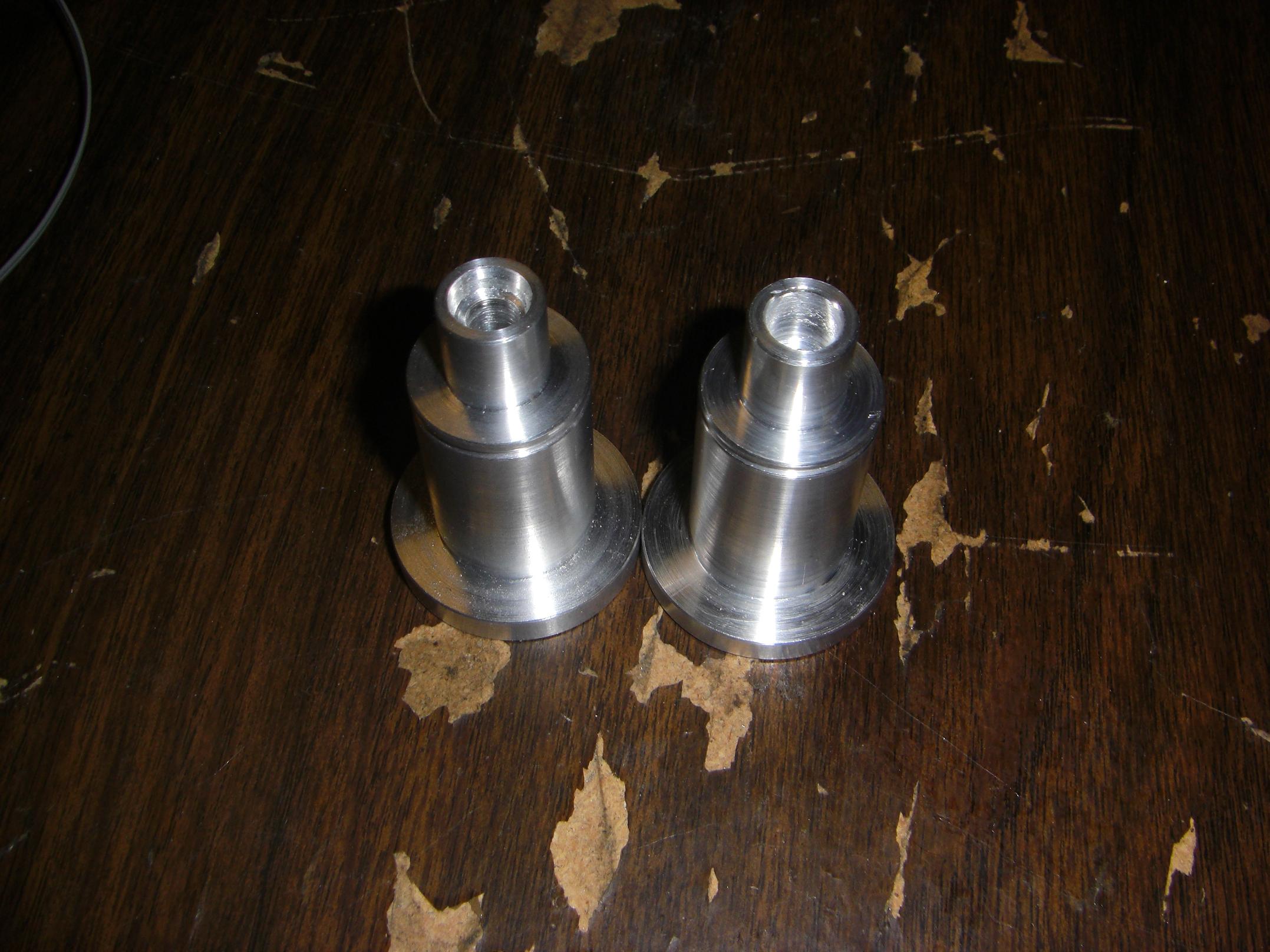
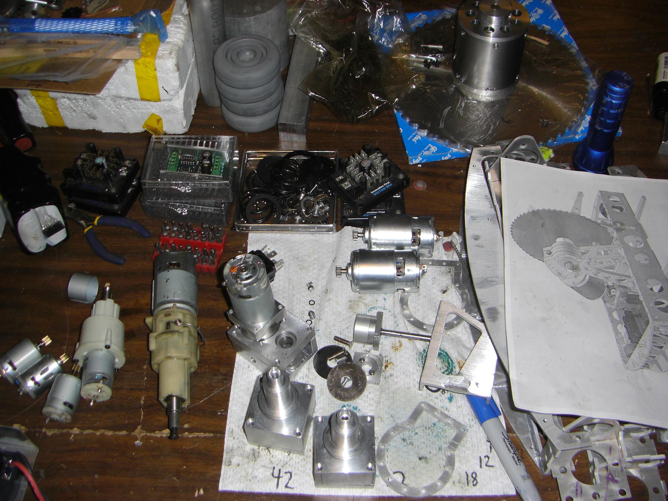
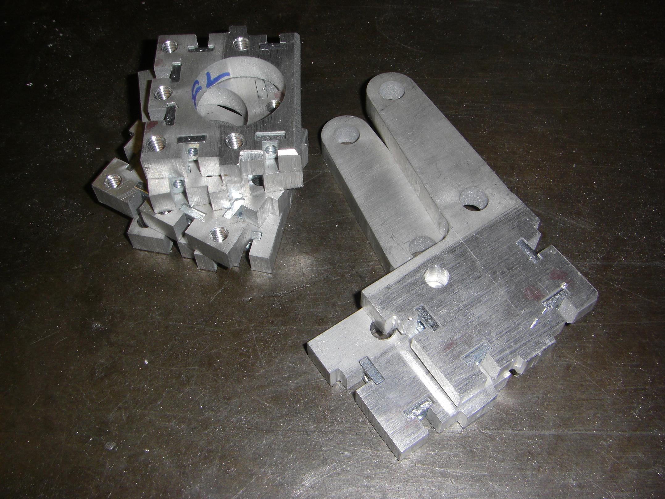
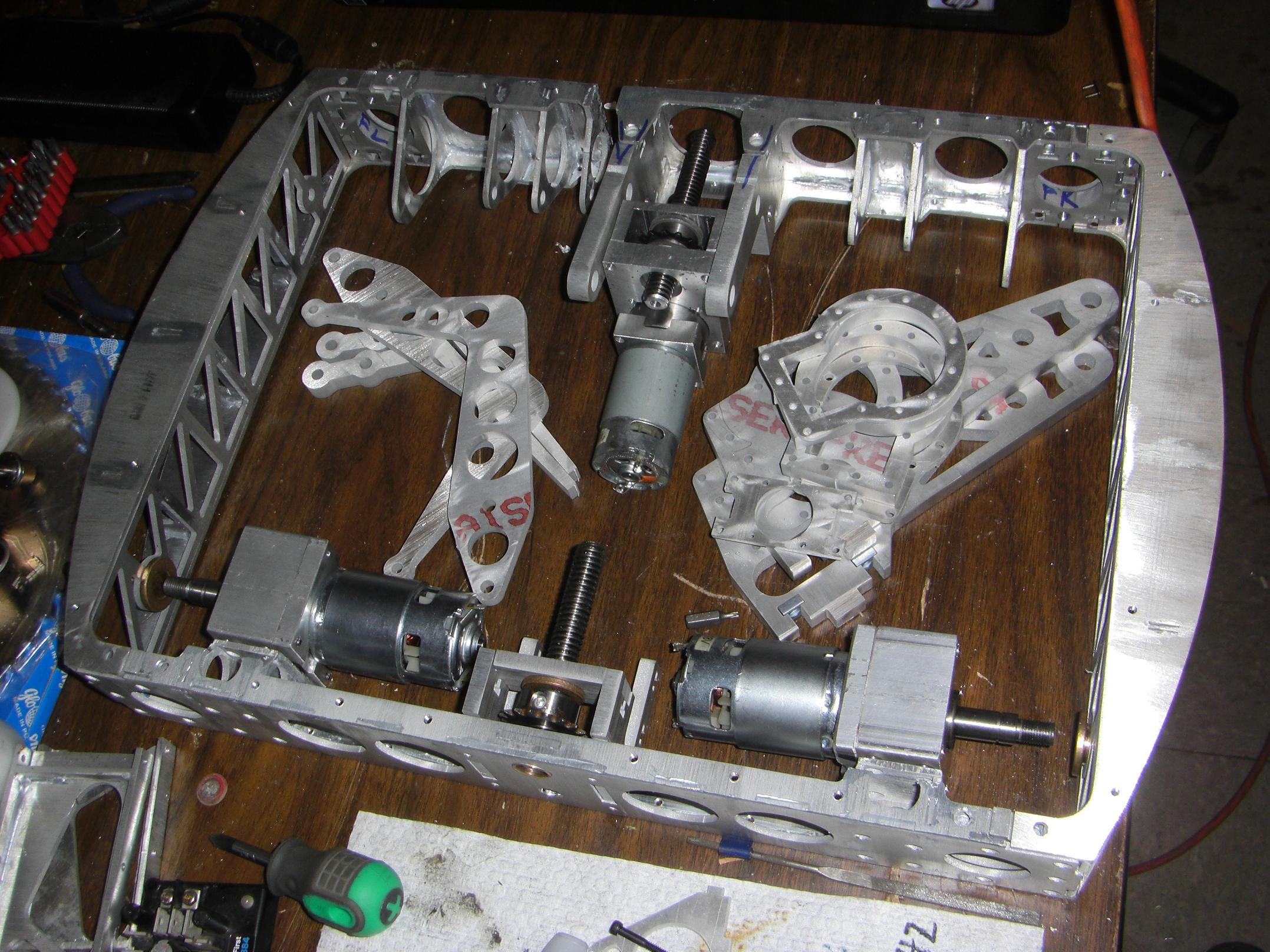
Pictured here are most of the parts for the swinging saw assembly and the two clamping fingers. These almost go together as-is.
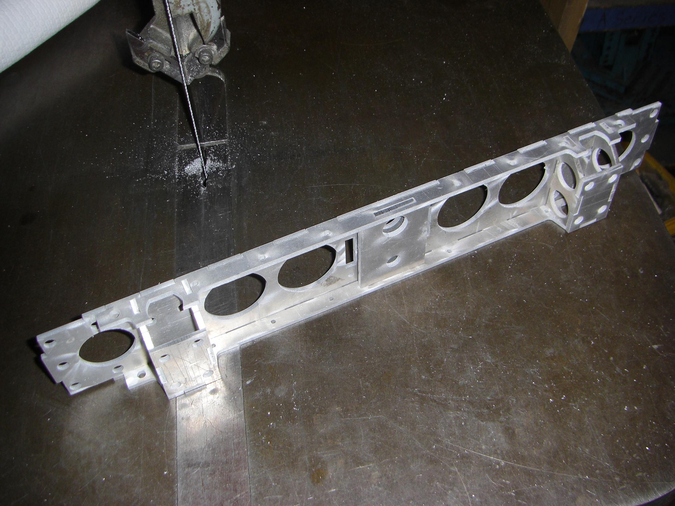
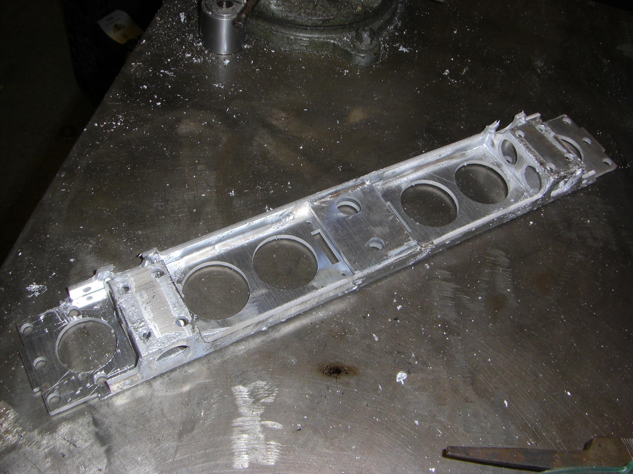
Back frame rail temporarily slipped together. Drive motors mount to the two projections, and the clamp actuator is (mostly) integral to the frame itself.
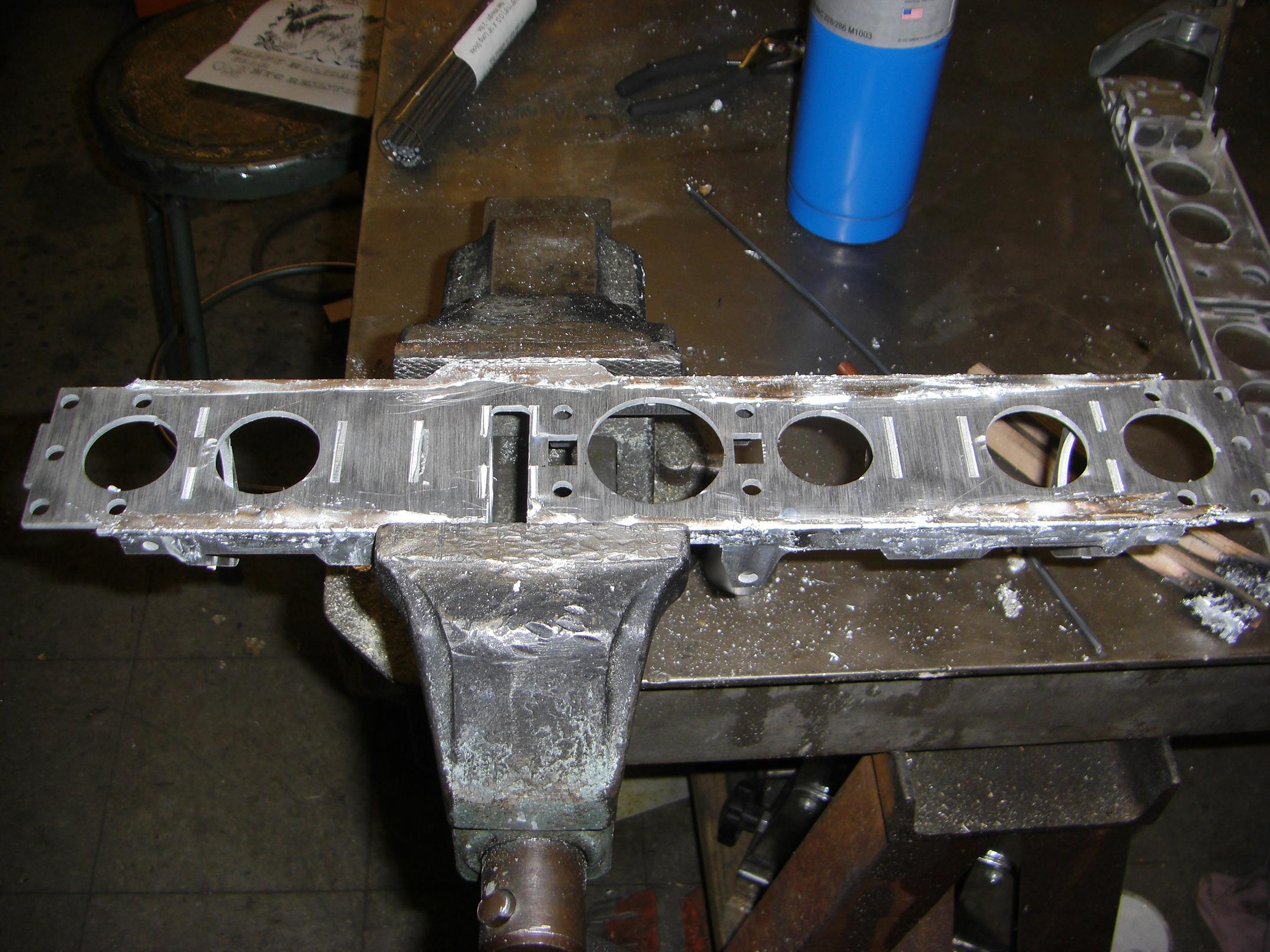
Here’s the front frame assembly in the “glob on as much brazing alloy as you possibly can” stage of fabrication. I heat up all the requisite areas of the metal and liberally distribute and wet the surface of the aluminum at the tabs with the zinc-aluminum braze.
The interior fillets on this piece are some of the best joints I’ve done so far. I was able to properly fill these joints because of…

…my +1 Frayed-Aircraft-Cable-And-Chunk-Of-Copper-Tubing Brush of Oxide Breaking!
Instead of ordering $9 stainless steel pencil brushes from McMaster, I chopped one up out of some stainless steel aircraft cable and the nearest small tubing I could find. In retrospect, making the handle out of copper, a highly heat-conductive material, was probably a bad move.
The long and thin pseudobristles allowed me to get the brush into narrow corners where my stainless steel toothbrushes could never hope to go.
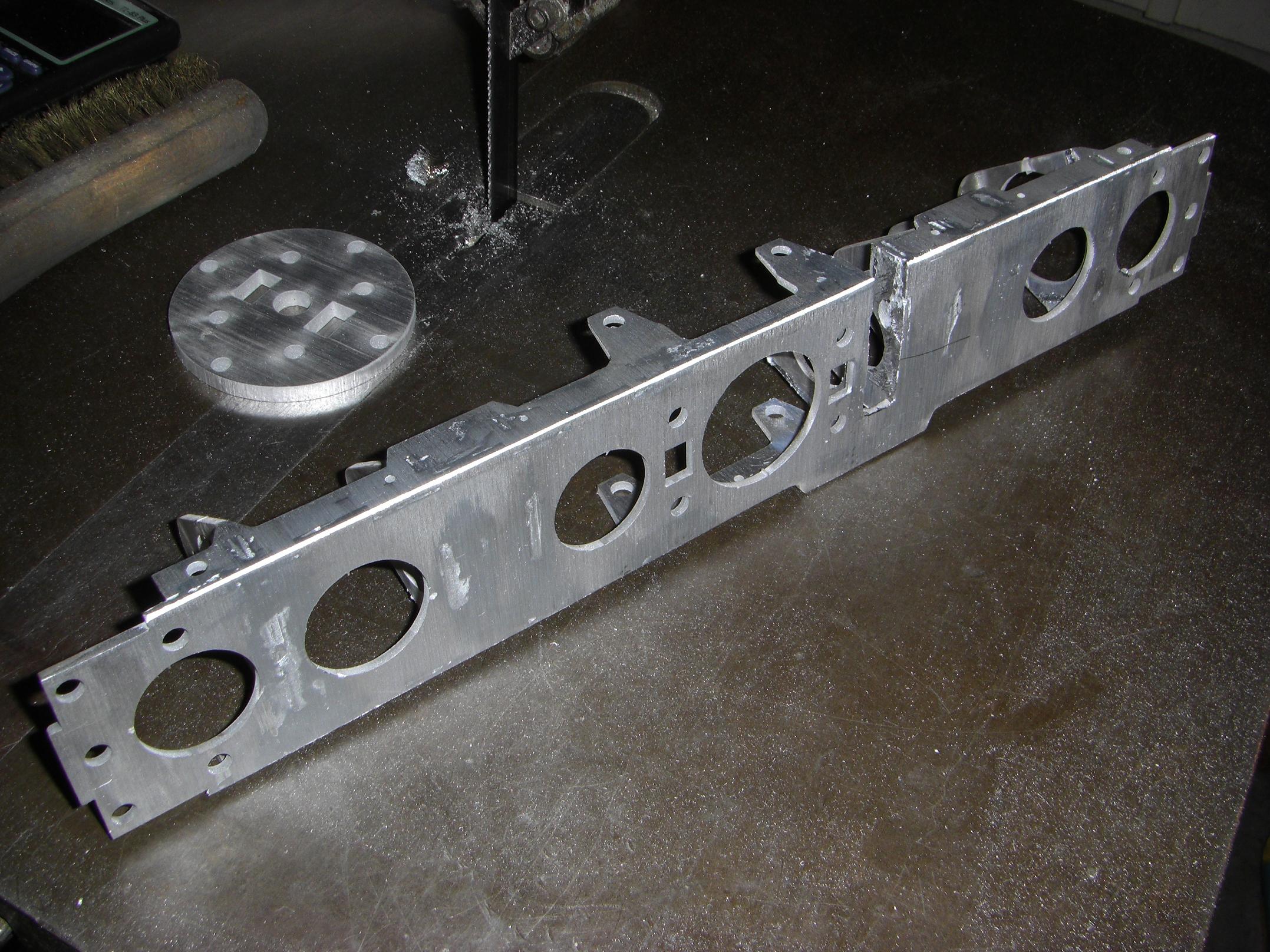
The stage after globbing is sanding the proverbial daylights out of the part. Using a large and wide belt sander helps establish a new flat surface that somewhat resembles the old. This actually makes the whole part look really nice, almost like it was meant to look like that!
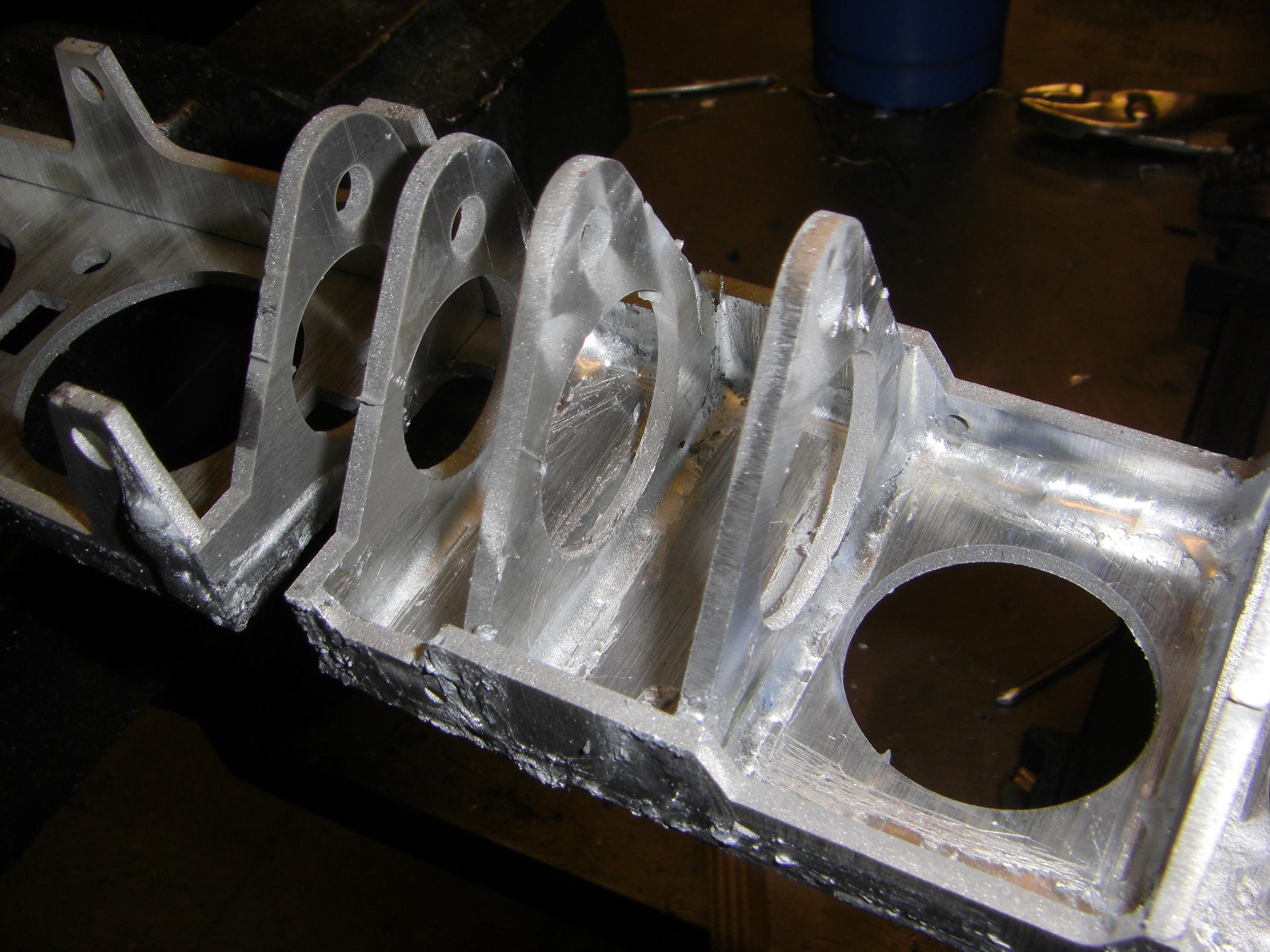
Here’s the backside in the globbing stage.
… and everything put together. Well, kind of squished together for the shot, that is. It looks great, but how well will it perform…
T-nuts installed into the thicker frame components. The waterjet cuts accurate enough such that these things either press in with thumb pressure, or, in the worst case, require a tap from a rubber mallet.

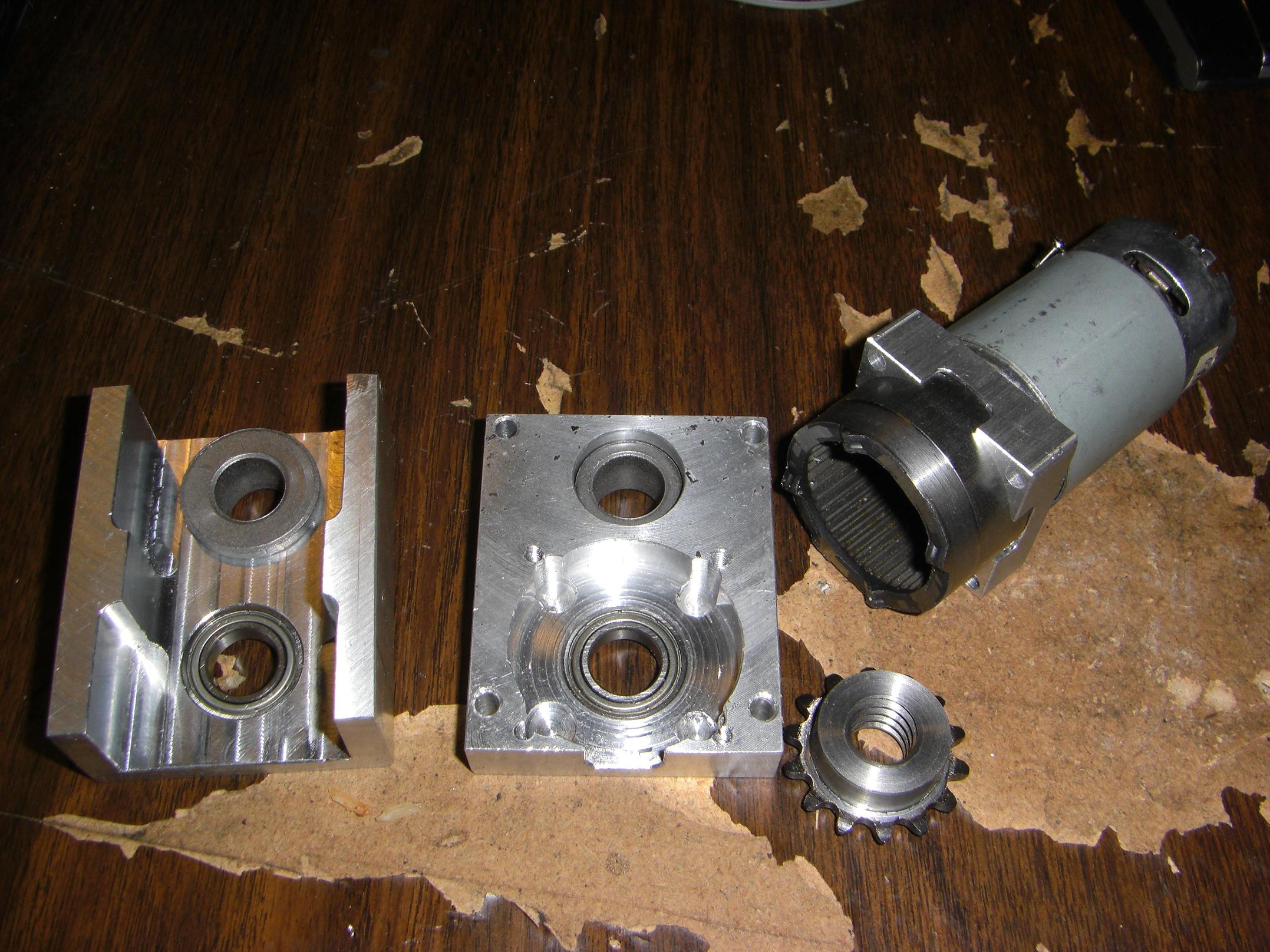
Mocking up the rear actuator. The bottom plate hole pattern mounts a Banebots 20:1 28mm gearmotor.

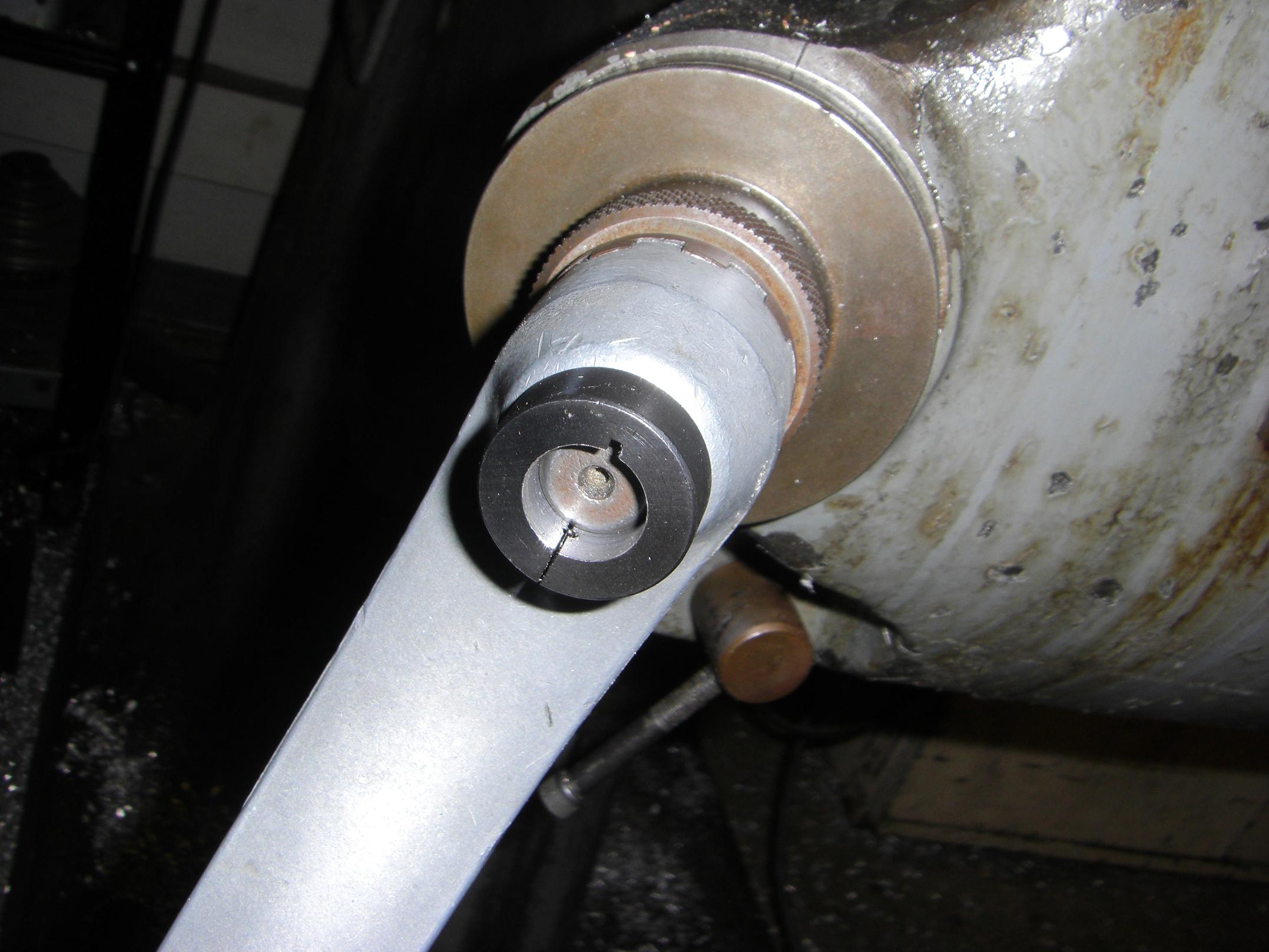
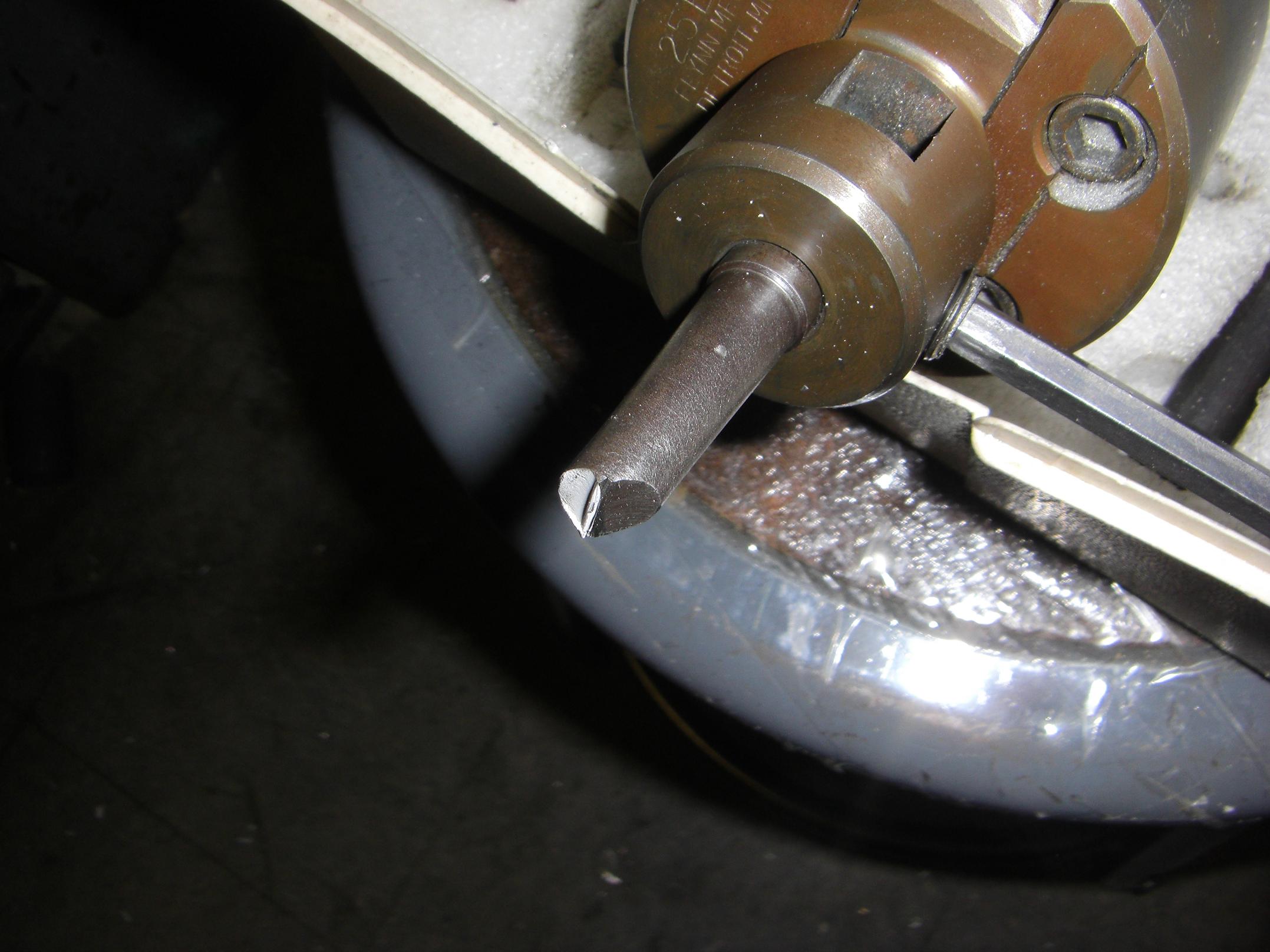
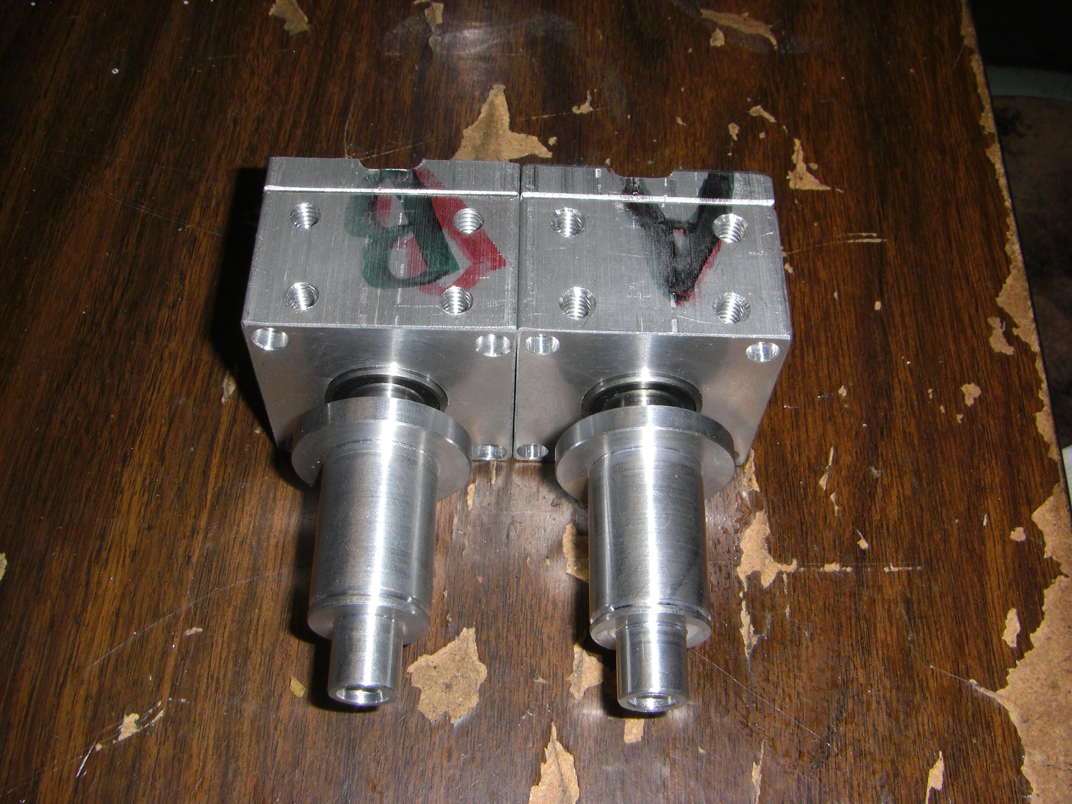
I bored, drilled and tapped one of the Surplus Center sprockets to fit the 1/2″ ACME leadscrew. The screw itself has two flats to let the set screws grip properly, and an end-threaded hole to act as a physical stop for the clamp.

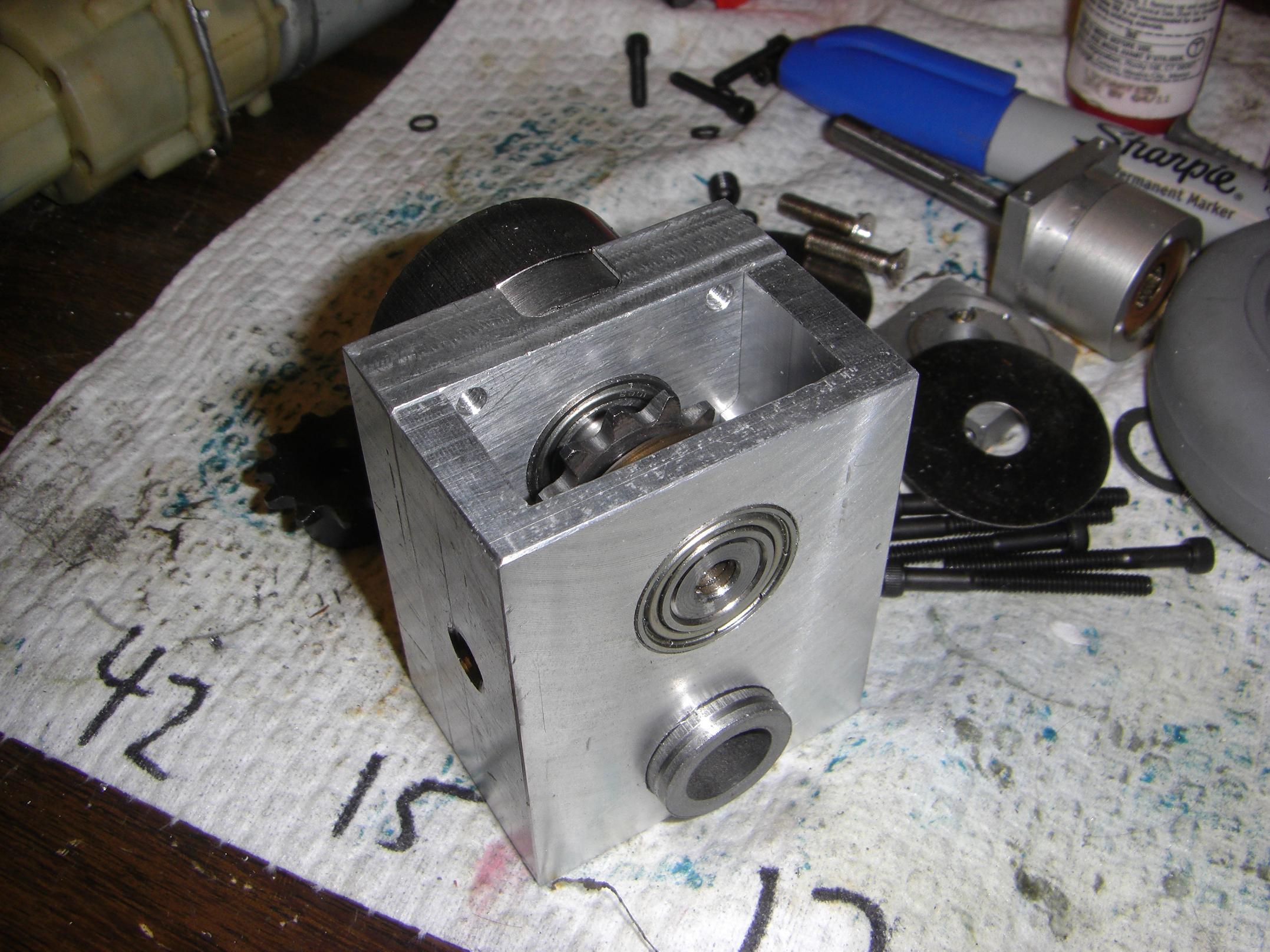
I ran into a foreseen-but-ignored problem when making the output shaft for the saw actuator. 11 tooth #25 sprockets have a hub that is barely over 0.5″ diameter. The output shaft of a drill gearbox is typically 12mm, or 0.472″. I already sized the output bearings for 12mm.
So that means there’s no way to actually attach the sprocket to the shaft. Too little thickness to set screw or cross-pin, at least that I was comfortable with. While I could have turned the drill shaft down, this required either changing bearings in the actuator body or making some kind of adapting sleeve. I thought the 11 tooth D-bore motor sprocket (from a scooter motor) that I found would save the day, but alas, it was 10mm.
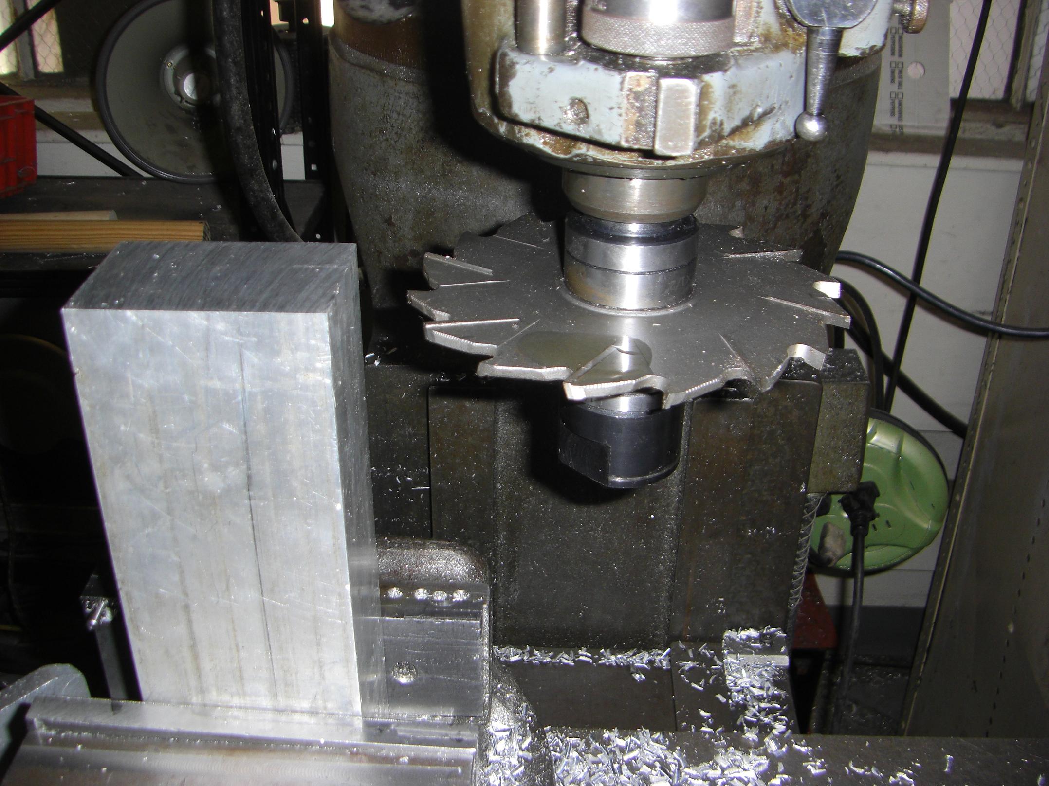
Naturally, I take the solution that would allow me to abuse machine tools: Make the sprocket hub bigger.
Uh oh.
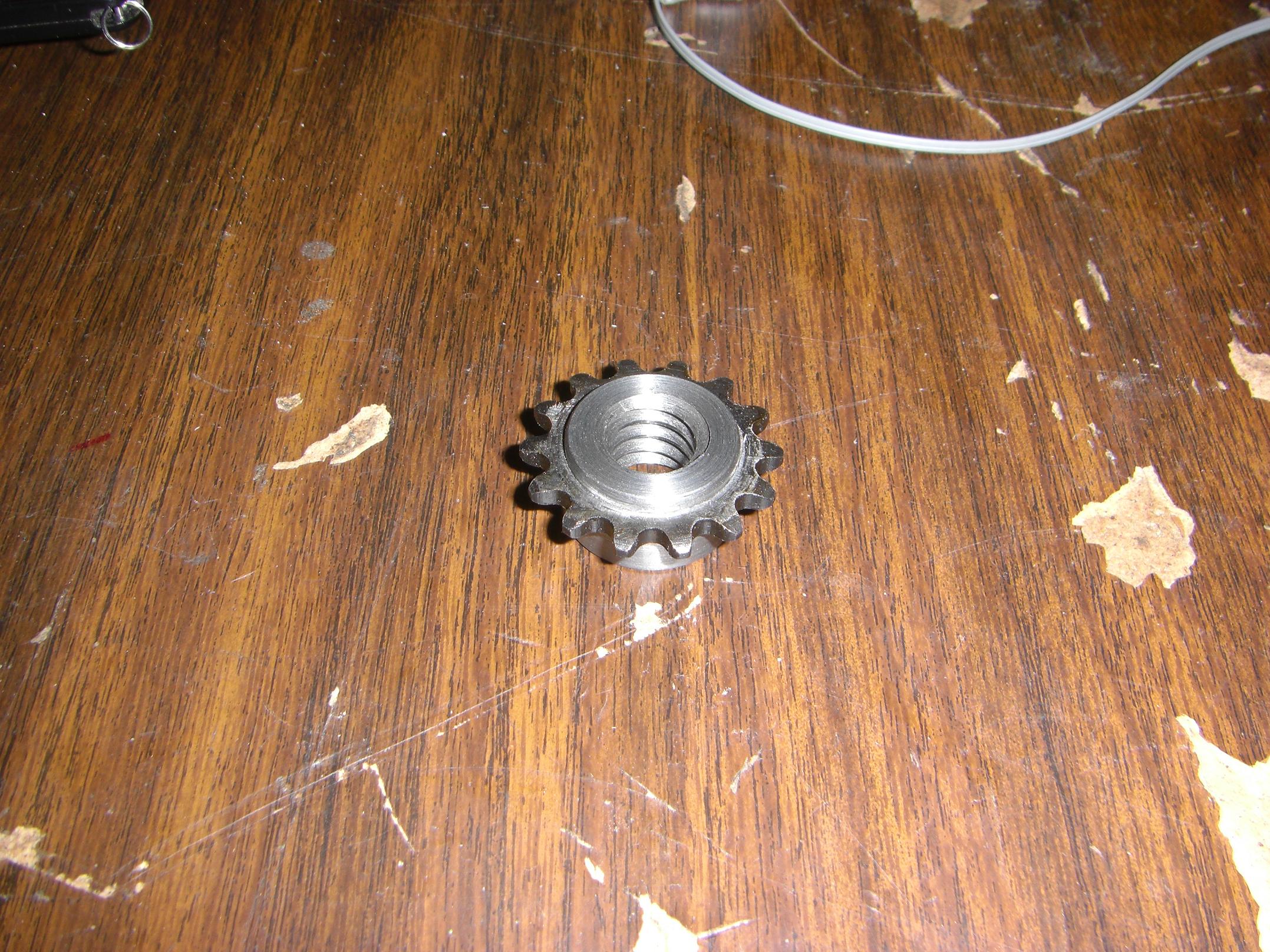
I turned a steel ring that was fitted over the existing sprocket hub. This increased its diameter to around 1″.
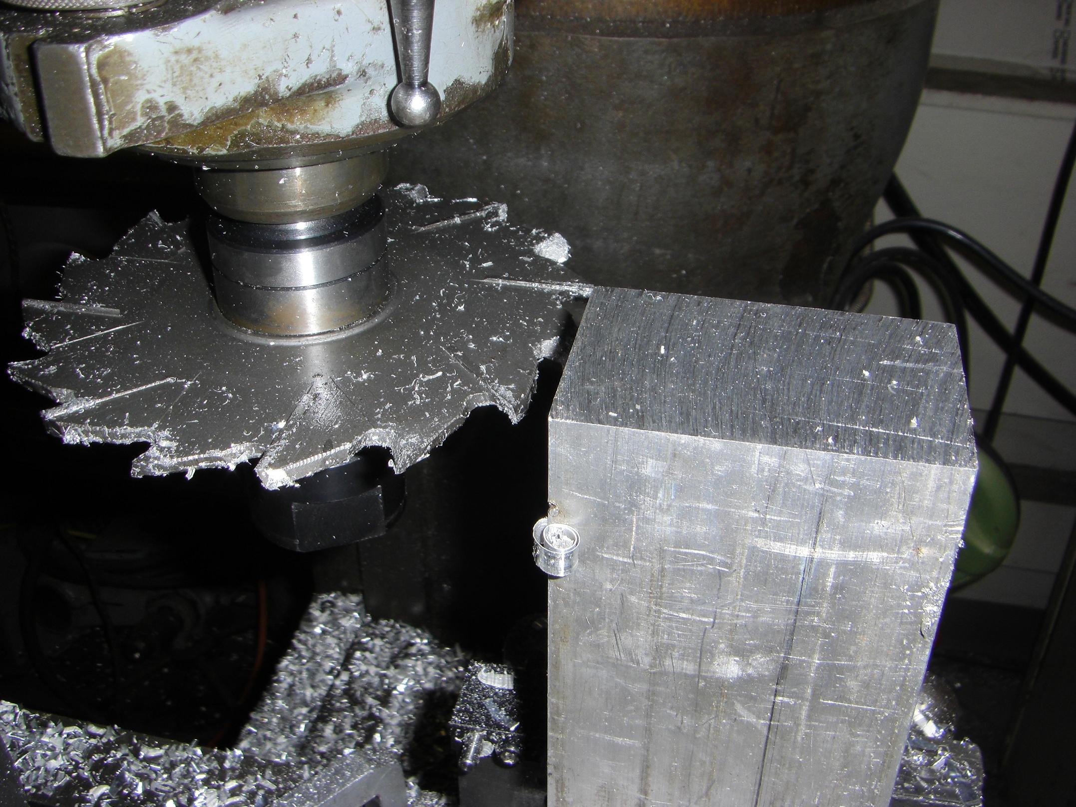
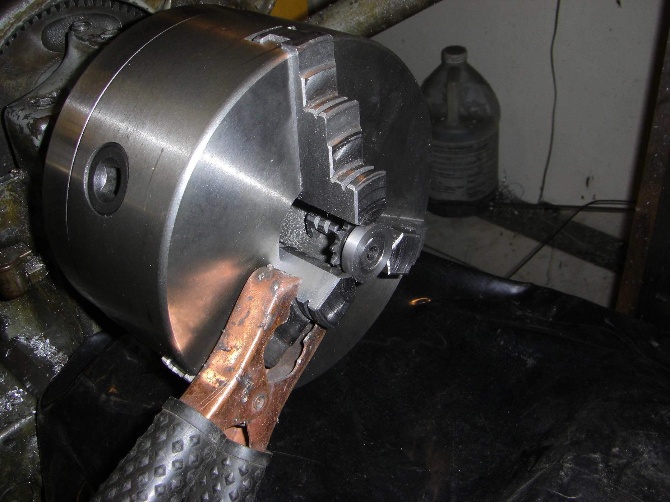
Then I welded the ring to the sprocket on the exposed end. While all this was fixtured on the lathe chuck, of course. The sensitive machine surfaces were covered with a welding blanket first.
I could have done this on a less expensive or important fixture, but the steel ring bore was a hair too big to align properly without wobble. I used the machine spindle to correct the wobble, and decided to just weld it right there while everything was still squeezed together.
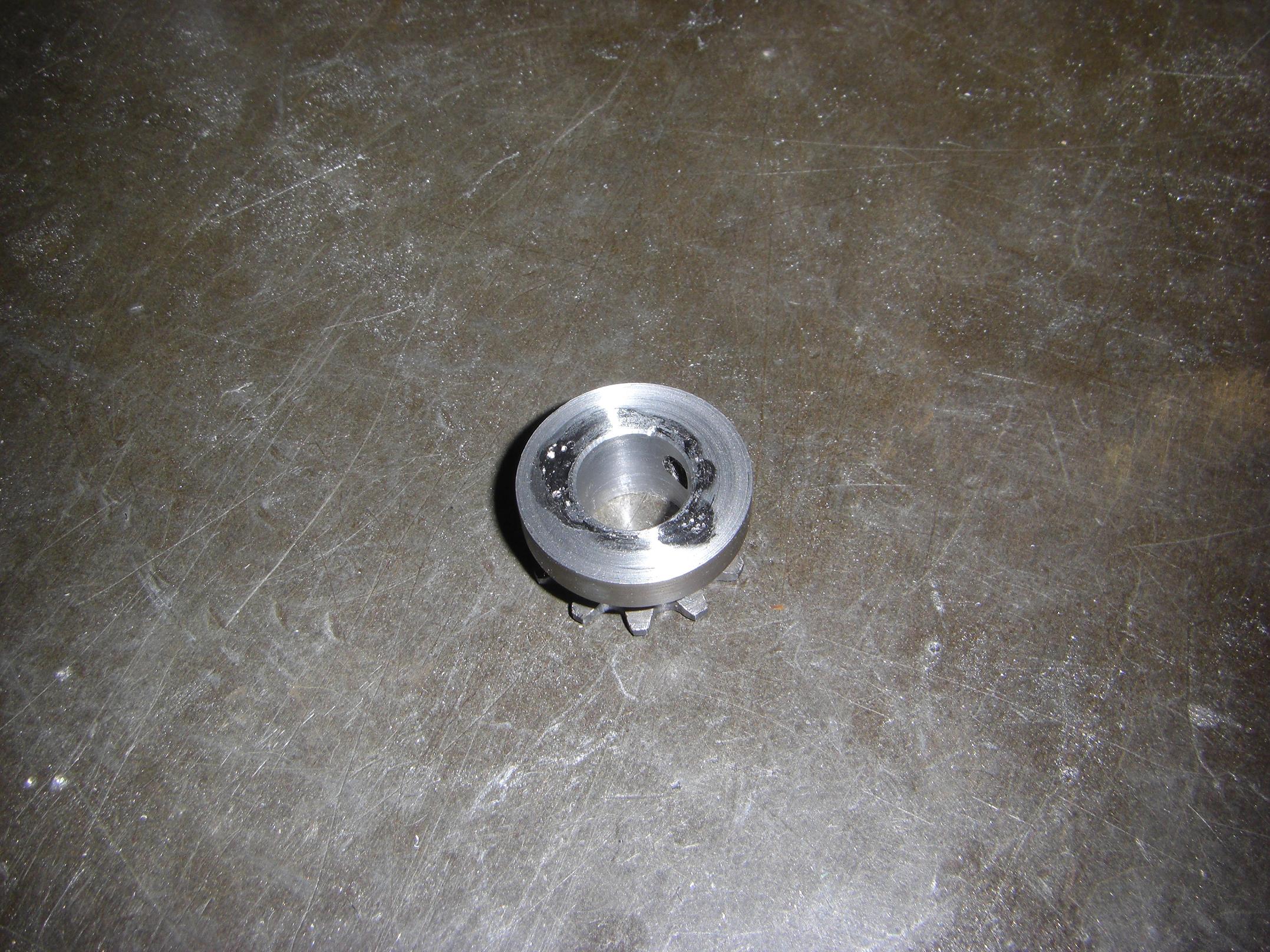
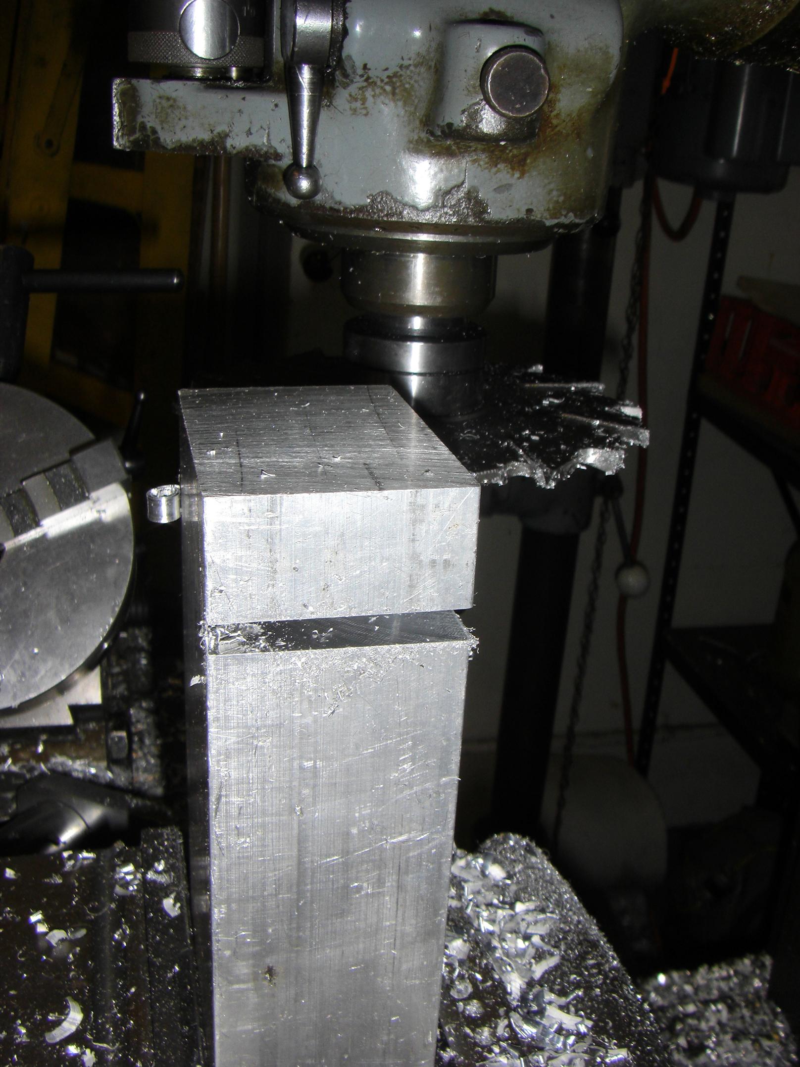
Mmm… porosity. After depositing the weld, I turned the surfaces clean.
You can tell I didn’t focus very hard on cleaning the sprocket surfaces beforehand. Oh well – this isn’t going into space.
And all ends well.
Not really a pretend-o-bot, but more parts are assembled. I got some 1.5″ long cap screws to close up the gearboxes, so now they are actually complete. I still need to find a replacement 400-size motor that can stand 18 to 20 volts, however – the stock BB motors are only safe to run up to 12 volts or so.
Things left to do:
- Finish the saw assembly, including all the random pins that attach things together.
- Give Deathrunner some windings!
- Front wheel hubs
- Waterjet the last of the components – electronics mounting provisions in particular, and the top & bottom plates.
- Design this stuff first.
- Panic
- Panic
- Panic
- Panic
- Panic
- Panic