Dragon*Con 2009 and Überclocker Remix: Epic Failwin Edition

So it’s over.

The lesson learned this time:

No matter how good of an idea you think it is to use sketchy $2.50 surplus drive motors, IT ISN’T. There’s a reason they’re on the surplus channel AND really cheap, it’s because they suck.

Anyways, here’s the pretty picture of the robot that I promised. What better backdrop for angry \m/echanical \m/ayhem is there than a flower garden?

I brought with me some assorted lighting products to comply with the power indicator requirement. So, some blue LEDs and resistors later, the bot had a “body glow”.

The emission of the LEDs is captured well by the camera. It’s actually much bluer in person.

After a last overview to add threadlocker on screws that were finger-tight for testing, I threw the robot and associated equipment back into the crate and hauled off to the event.

I ended up not bringing any insect bots this year, so there’s no bot report on the Sunday ants and beetles tournament, but I did take some pictures.

Anyways…

Welcome to Dragon*Con.

The most eclectic collection of comic book heroes, SciFi characters, anime schoolgirls,  ambiguously-gendered deviants in locally popular indie bands, and much much more, in the universe. This guy worked two years on a painstakingly accurate interpretation of… a character I have not heard of in a show I have not watched.

In the middle of all this, somehow, is robots. I am satisfied.

Here’s the “Microbattles” event on Sunday, which features full enclosed-arena combat with 1lb and 3lb bots.

Returning again is the super legit Atlanta Antweight Arena™, a 6 x 6 foot, quarter-inch polycarbonate-sheathed Box of Awesome.

After the last arena hazard exploded off in a violent expulsion of wheel chunks, plastic shavings, and angle grinder gears, it was determined by the community at large that robots should be less amenable to destruction via the hazard, and that the hazard should be designed more for… well, fucking around with the match.

So the new arena hazard is a solenoid-driven flipping ramp that is weight-sensitive. On average, when it is functional (i.e. the latch isn’t jammed), it will pitch a 1 pound robot a few inches up and two or three feet over.

My suggestion of a powered turntable was turned down.

Robots at the event ranged from the compact, durable, and elegant, to…

Yeah, about them robots.

Here’s a picture of robots (Segs and Pwnsauce). Fighting. Like on Battlebots.

The main event is a highlight during the Monday of the con, which is when things are always ending or wrapping up. It’s an open stage sumo-type event where big spinny things are not allowed due to the peculiar fact that the arena wall is the audience.

No, not really. But they still don’t allow spinners, flails and chains, or other surfaces that could conceivably travel at more than 20 feet per second, the prescribed speed limit.

The combat stage in question. Always the shittiest, most beaten up, and uneven stage risers that the hotel has, and usually recycled from the previous year (and beyond!), then littered with audience-sourced stage hazards to make life more interesting.

This year, we have objects as diverse as to run the gamut from shoes to donut boxes.

So about that whole robot fightin’ thing…

Bots at D*C tend to be less SRS BIZNESS,  if the brightly painted lawn mower shell with a popcorn toy on top doesn’t tell you already, than the more professional league events due to the fact that there’s nothing really to win besides glory and a plaque…. and the hearts of nearly a thousand audience members at any one time. The event average 80% seats full and approached standing room only at the end. Coming from a harder combat background, I’m slightly jaded, but the average Stormtrooper finds this very amusing.

Usually, big steel bars are bolted into the stage riser surface to perform one of several functions. They act as more floor hazards to discourage plain box and wedge designs which, while effective, are boring as hell.

They also, as was discovered at this event, keep the risers together. A few good shoves from flying 30 pounds robots and inches-wide seams would open up in the floor because the risers would physically move from the impract.

Floor-scraping wedges have a hard time navigating to begin with, but fast ones begin tearing up the stage surface. A few seams and edges had to be cut off, hammered, or re-screwed as the event progressed.

Here’s a cool shot of Überclocker performing clampbot gymnastics.

Okay, so that’s totally and utterly staged, but for good reason. I actually played most of the tournament with either one function drive side (the left one) or none at all.

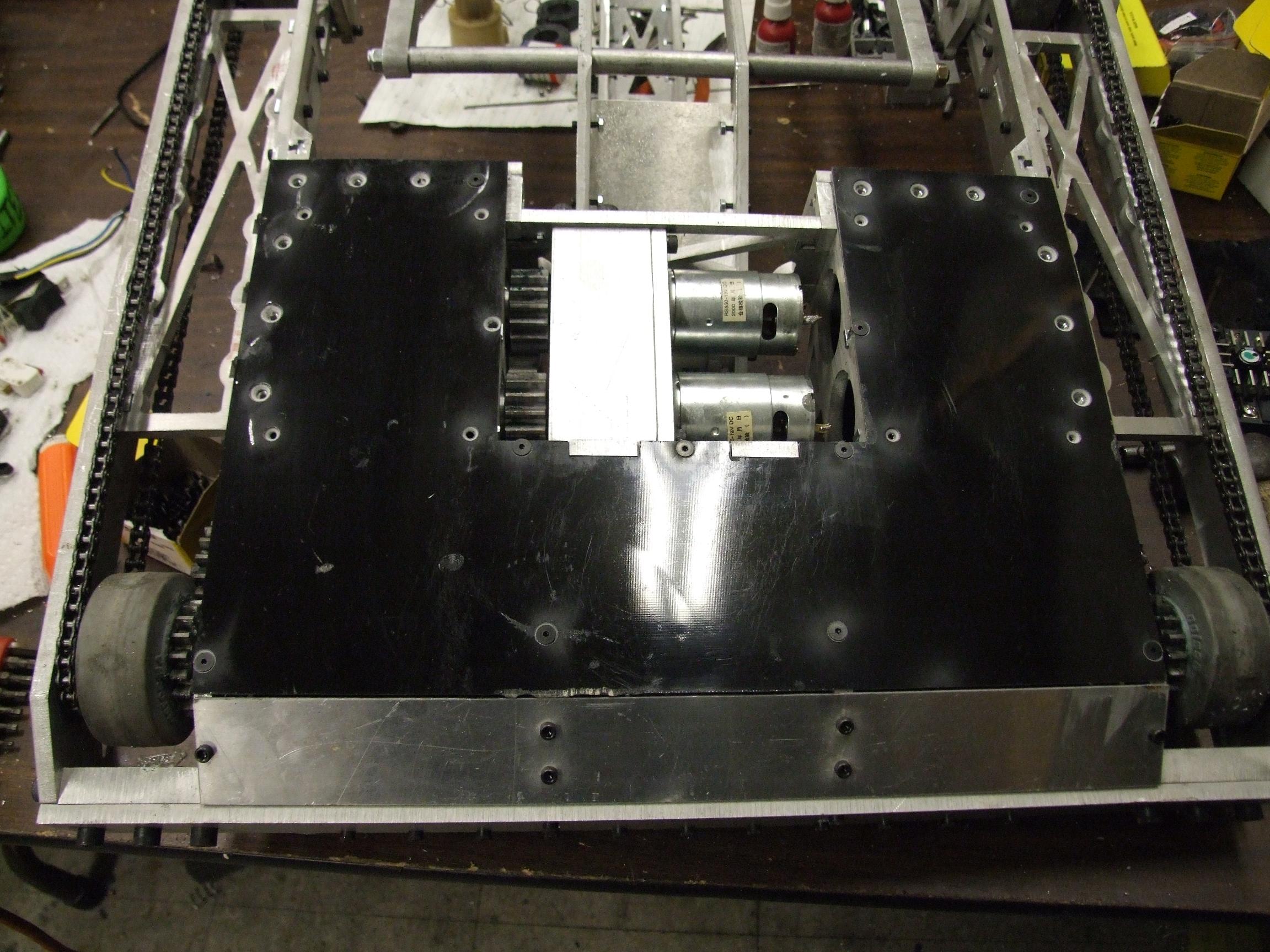
Why? Because my sketchy-ass $2.50 surplus drive motors let out the smoke like nothing else I have ever seen.

I actually lost one of them before matches even started. During some test driving on the stage, the right side motor ceased functioning. By that, I mean if you try to power it, huge sparks shoot out from the brush end. Not smooth for robot work.

Knowing the bot wasn’t going to win at that point, I sort of just tossed it in the tournament for grins and chuckles™. This involved starting in increasingly absurd positions as the matches went on – it was a round robin tournament, so I had plenty of time for showmanship.

The reason for the failure is still unknown, but there was no way the bot would move at all with one motor dragging on the right side. So I took it out – leaving only the gearbox to add a very minimal amount of drag, so the robot would tend to curve in a wide right cirle.

The last minute hack that saved me to some degree was turning Überclocker into an elaborate cheap R/C car. You know, those things which go forward, but then turn in one direction when they reverse.

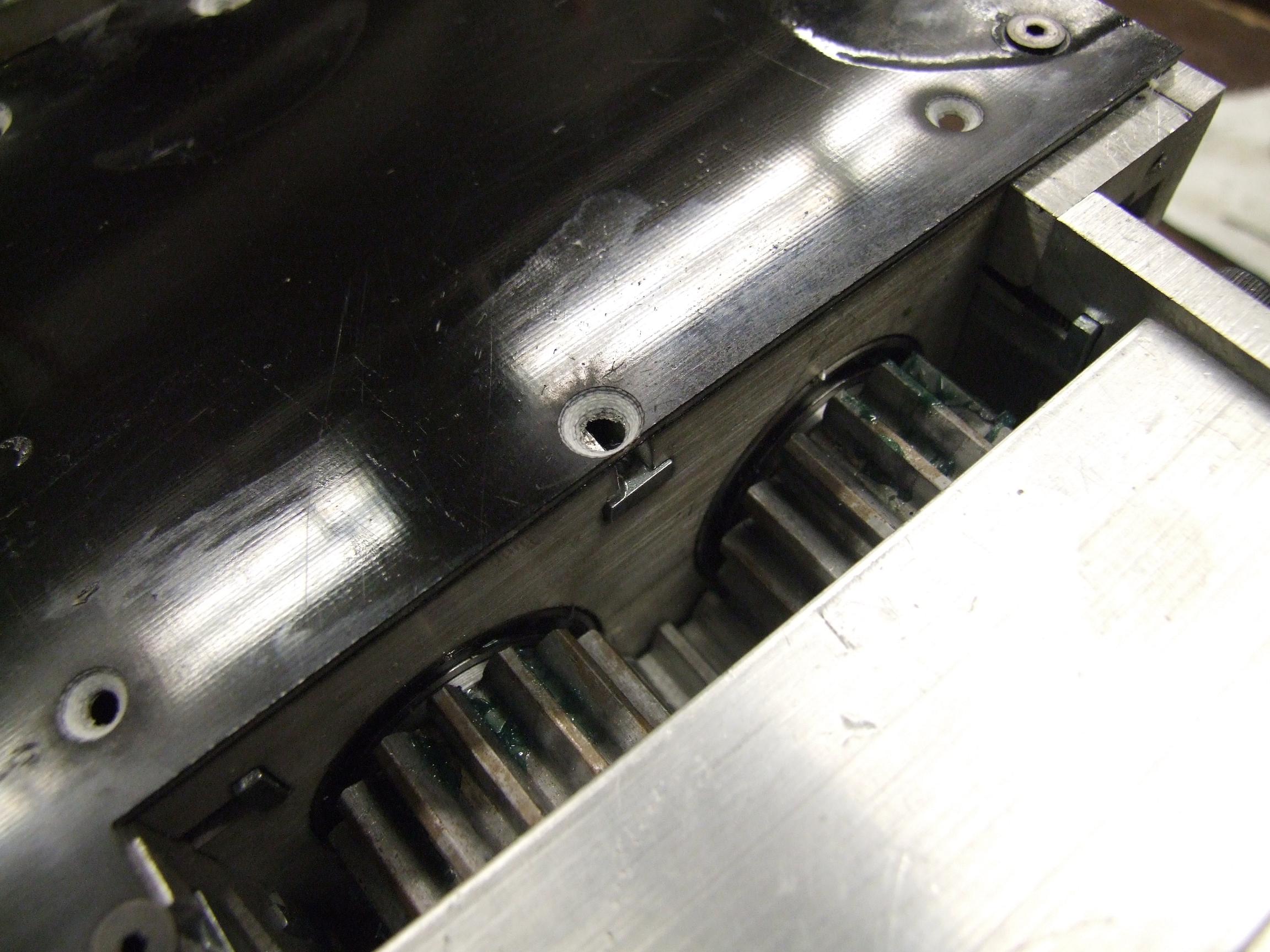
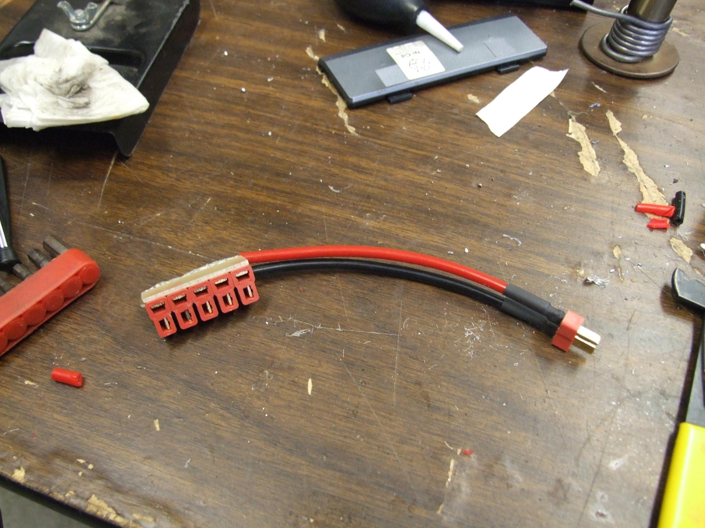
The magically-multipurposed zip tie comes to save the day. When the robot rolls forward, the gears bump the cut wire tie out of the way, and the robot moves without restriction.

However, when the robot attempts to reverse, the zip tie gets sucked into the gear teeth, jamming the wheels. As a result, the robot swings a left turn about the rear right wheel.

It was a very limited form of maneuverability that opponents were about to take advantage of, but hey.

See it working in the highlight video!!

Wrapup

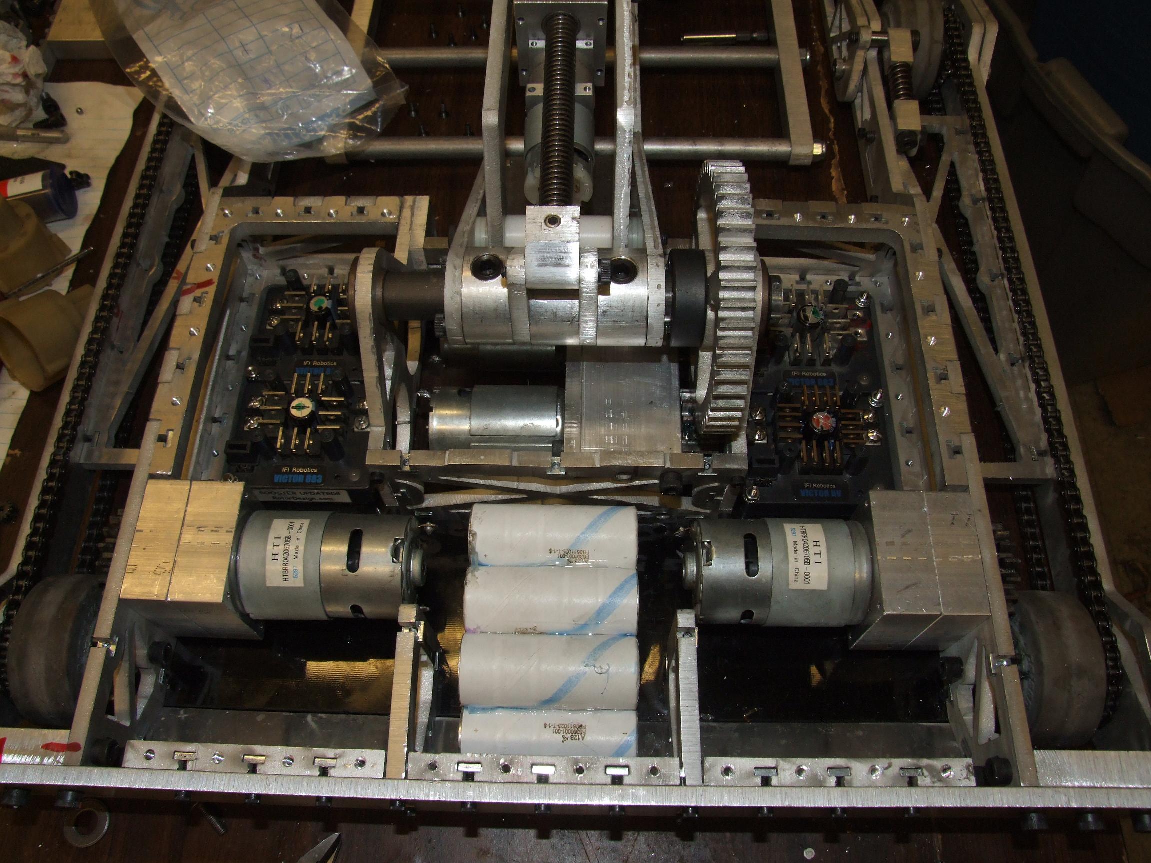
You know what… for once, I’m actually satisfied with the robot. The failure this time was not something conceptual or something I had to fabricate. The fork and clamp worked extremely well when I could capture opponents, and the robot actually did not faceplant on a lift attempt. The torque limiting solution for the gearbox also worked excellently.

The only thing I need to do is not go “ooh, cheap and shiny” as much…especially on something as pivotal as drive motors.

Überclocker will probably compete in regional Sportsman 30lb class events and will return to Dragon Con next year. In the mean time, I have a year to perform upgrades and rebuild the insect bots that I neglected this time.

Überclocker Remix: O GOD AAAHHHHH

So it’s been positively determined that no, in fact, I cannot build robots synchronously with Orientation week. At the very least, Überclocker has made it to the “96.6% complete and only needs tuning and LEDs) stage of the build, and so I can run at Dragon Con if I’m careful on the sticks.

I chose to leave all the controllers open loop this time, unlike the last bot which had a closed hastily knotted and zip tied loop servo control on the fork. The low refresh rate of R/C signals and the intolerably wide deadband of the Victor controllers sort of made that a disaster.

The bot has already lost a motor in testing – the Banebots (go fig?) motor on the clamp arm actuator stopped functioning for no reason at all. Fortunately, I had a spare ready to throw on, and so there is no need to re-engineer the whole thing like I did last time. 

Everything made it to Atlanta with the only cost to me being a $119 oversize-overweight-holy-shit-are-you-serious baggage fee from AirTran, and entry onto any one of several Federal government watch lists…but I assume they already had me on there anyway, so that’s not really an issue.

Here’s (‘re?) some pics from the past week or so of on-and-off high-intensity robot beasting.

With the build rapidly approaching the limits of the extant design, I had to pull out the old CAD at night, build the next day card on the electronics mounts and top and bottom covers.

I tend to concentrate the robot electronics in one or two small areas in their own mounts as opposed to zip-tying and hot gluing to random structural (and nonstructural) areas of the robot, as I used to do. Through a nontrivial amount of Victor-stuffing, I managed to shove all 4 of them into the hastily laid out component spaces.

This didn’t leave much room for my usual standoffs and spacers, so I decided to make the Vics themselves structural.

IFI controllers all have little posts upon which their stock fans mount. If I didn’t need those fans, I could use them to mount other things, like the upper deck of the electronics bays. They are the light transparent blue plates in the screenshot, to be made out of something light and plate-y, but not necessarily transparent or blue.


I also fired off the design for the top and bottom cover plates. They are to be made from 1/16″ Garolite (fiberglass-epoxy layup similar to circuit board material), because four square feet of carbon fiber exceeded my strength-to-taste-to-price hyperratio.

Because the top plate was actually three plates, I elected to not cut a huge clock logo into it like the original spec called for.

Instead, I was able to insert yet another gratuitous MIT logo.

Here’s a picture of an intensely-delaminated fiberglass sheet!

So because I have been in a waterjet shortage crisis at MIT, I took what I could get – about a half hour’s time on one of the first OMAX machines ever built.

It was by far the sketchiest abrasive waterjet machine I have ever personally used. So sketchy, in fact, that you had to hold the abrasive feed tube in when the pump first starts.

Yes, that’s correct. After all the shop safety Nazi-ing and training I have been put through in the past few terms, the first instruction I get is along the lines of

“Yeah, you kind of have to hold the nozzle while you hit start.”

Beautiful. Besides that, tending to cut large trapezoids, and freaking out if the zeros are not set to its liking, the machine was well-tempered.

I don’t blame the delamination on the process. More like I forgot to bring my scrap plywood backing and overlay material that would have completely prevented the pressure from blasting the layers apart, and had to wing it with…


…thin aluminum sheet, which didn’t really help with the laminations, but did produce me some spare armor plating if I needed it.

While I knew the fiberglass was never going to be flat again, I wanted to get rid of the big bubbles and at least close the edges. So I gathered the majority of MITERS’ clamps and some bulky flat metal scraps, shot epoxy into the bubbles, and cranked the whole thing together.

Instead of sitting and watching glue set, I started assembling the electrical system. Here are the “eBay” plates, cut out of 1/8″ black polycarbonate. I didn’t get any clear or shaded polycarbonate, so grunged a 1/8″ scrap plate from the Media Lab basement.

Those notches on the sides are to clear wiring and give screwdriver access to the Victor’s screw terminals.

Okay, good enough. The bottom plate is actually pretty clean. Here’s the whole thing fastened to the bottom of the robot, along with the “taintplate” that covers the awkward middle zone between the underside and back.

The top side is hellaciously ugly, though. The battery cover is a big parallelogram that I had to take some sanding to, so ignore the huge janky gap between it and the robot’s right side. Otherwise, everything fit well.

So even with a computer controlled machine starting a hole in the precise location I need for me, I still somehow manage to miss when finishing it.

Depreciation of manual fabrication skills fail.

At about this time, I found a roll of leftover Mylar film. Mylar is a metallized polyethylene teraphthalate (say that 3 times fast?) plastic that is really fucking shiny. So, what better use of my time is there (besides finishing the robot) than to totally make those awesome cutouts SHINY?

Little mylar rectangles cover the holes from the underside, secured by patches of Kapton (another weird-ass but high temperature and strength plastic) tape.

In a further effort to distract me from the robot, I sharpied the squares to match the MIT color pallette (of the i-stem always being a different color, to represent uniqueness or something…).

This was around 5 in the morning. You’ll have to excuse my absurdity.

I plastered another piece of Mylar on the other half of the bot and called it a day.

Time to amp up (LULZ) work on the electrical system. Here’s my amazing battery-gluing jig.

I used Shoe Goo (related: GOOP, E6000) to fasten the cells together. It belongs to a family of rubberized contact cements that have a number of perverted uses.

No, not that kind of perverted. Or that one. What I mean is that the properties of the stuff – solvent based, fast-evaporating, rubbery, and very durable unlike silicones – makes it useful for not only gluing stuff together, but also insulating wires, potting electronics, making robot wheels, and other structural uses.

The battery will be a 7S A123 26650 LiFePO4 (how many numbers and acronyms does it take to get to the Tootsie Roll center of a Tootsie Pop?), made of trimmings left over from electric vehicle work that didn’t pass the fast-charging regiment. But they’re plenty good for robot duty, where I won’t be charging at 10-minute rates.

I plan on making a few packs for the bot and swapping them as needed as opposed to charging in-bot. While iron phosphate type cells are substantially less temperamental, swapping packs is still physically faster.

The cells will reside in the rear-center of the bot, in its own little foam-padded cubby.

All done, forgot to take pics, etc. etc.

I used the awesome Miyachi-Unitek BATTERY TAB WELDER!!! loaned to the MIT EVT to assemble these packs. That turned an hour of soldering and getting totally baked off the rosin fumes into 5 minutes of “click” “bzzzzt”. It was the quietest 2000 amps I have ever flowed through anything.

I also inserted some foam rubber into the heat shrink tubing before taking the heat gun to it. Overall, everything came out well.

Overview of all the electronics, before adding wiring and solder.

On the right side, the pinion retaining screws come a little close to the power terminals. Fortunately, there is enough vertical distance to pass crimp terminals through.

Real electronics assembly begins with the assembly of SUPER DEANSBUS™, which is my way of saying “a bunch of Deans T-connectors glued together in a row”. I didn’t have the space for a legitimate terminal strip, so I opted for this method of power distribution instead. While a terminal block could ultimately be faster for swapping out components, I also… had a whole bunch of Deans connectors. So why not use them?

Super DeansBus assembled with the breakable-link pigtail. Instead of going for an Epic Switch like on ‘clocker 1, I just elected to use the simplest possible master power switch – the battery connector, leading outside and back into the robot in an inconspicuous location.

Pre-emptively adding pigtails to all the rest of the components.

Plugging in all the components to Super DeansBus. There are 5 slots – one per Victor, and one for the DC/DC converter that will supply the 5 volt logic with power.

I had trouble with the Victors’ weird reverse-polarized signal plug needing a male pin length longer than what I had already.

Innuendo-laden jokes aside, the quickest way out was snipping the pins off some wire-wrap chip sockets and soldering them into the end of a standard servo lead.

Pretty Much Everything™ loaded and ready!

At this point, I decided that the robot was good enough for a full power test run. After one last wiring sanity check and a pass with a voltmeter (you know, in case I soldered all of Super DeansBus backwards), we went out and shot some videos…

Some driving and lifting of the same 23 pound transformer doohickey a few update ago

I accidentally the robot, so here’s some self-righting. In the tournament, I’ll have to make sure I don’t try lifting anyone too far over the back of the robot.

I decided to leave everything for a little while to avoid artificially injecting electrical gremlins into the system, and started on preparing the robot crate. This is a Pretty Freakin’ Enormous 26″ x 26″ x 12″ … crate… with a hinged lid. I’m not sure of the actual name of this kind of crate, so “crate” will have to do.

It used to contain what appeared to be someone’s Soviet missile attack survival kit. On the outside, tons of old bumper stickers, mailing labels, and other adhesive ornaments. But on the inside were a dosimeter, a Tyvek full body disposable bunny suit, a Soviet propaganda poster, some Russian literature, and a bona-fide legit envelope containing a real U.S government issued potassium iodide tablet.

Holy shit, that’s badass. I pinned the envelope to the wall near the MITERS first aid kit station in case there’s a radioactive fallout incident or something. It should save us all. 

For the record, I found this sucker on the loading dock of the shop building, with no identifying information anywhere. So, to whomver just crawled out of the bomb shelter, I thank you.

To turn it into a robot crate, I stripped the interior of most of its foam lining and removed some wooden compartment dividers. And also made sure it wasn’t radioactive in any way, because getting that through airport security would have been amusing.

As a final preparatory step in making it Über-Legit, I spraypainted the MIT box logo and ‘MITERS’ in bright fluorescent and metallic lettering onto the sides.

Before I shoved everything into the box, I took apart my Spektrum DX6 transmitter to convert the left side (throttle and rudder) stick to full spring-loaded operation. Normally, the left stick’s vertical axis is the throttle of an airplane, and is either racheted or unsprung and damped in order to relieve the pilot of the effort of applying constant throttle.

For robot work, that’s a pain in the ass to drive with. The spring loading component were yanked from another (dead) transmitter. It is composed of a spring and a lever.

That’s it. Pop the spring in, pop the lever in, and connect the two. A five minute  operation that the hobby shop would no doubt charge you up the dielectric for.

Everything is going IN THE BOX NOW. I managed to bumble around until something like midnight, 4 hours before I had to ship out.  I cut up the foam from the original crate and arranged everything to minimize empty space. This thing was already 2 inches under Airtran’s oversize baggage maximum limit, so damned if I was going to leave air in it.

The final layout is actually very orderly.

Closed, and prominently featuring my complete inability to spraypaint something neatly.

So, I’m an epic idiot and didn’t take a picture of the robot before throwing it in the shipping case. After I unpack everything and start tuning the minor details (such as the fork sitting three quarters of an inch off the ground in the rest state?) I’ll put up real robot pictures.

Dragon*Con starts FRIDAY!!! and the event is MONDAY!!!

Sorry, no Nuclear Kitten and Pop Quiz this year. I’ll only be photographing and filming the Sunday ants and beetles event.