It’s late July. Why haven’t I seen a robot post yet, Charles!?
Well, too much LOLrioKart and lots of time taken up by my job building Terminators. But ‘clocker has been in the back of my mind for a while. With Dragon*Con and Robot Battles now a month and a half away, though, it’s starting to climb up the list really fast.
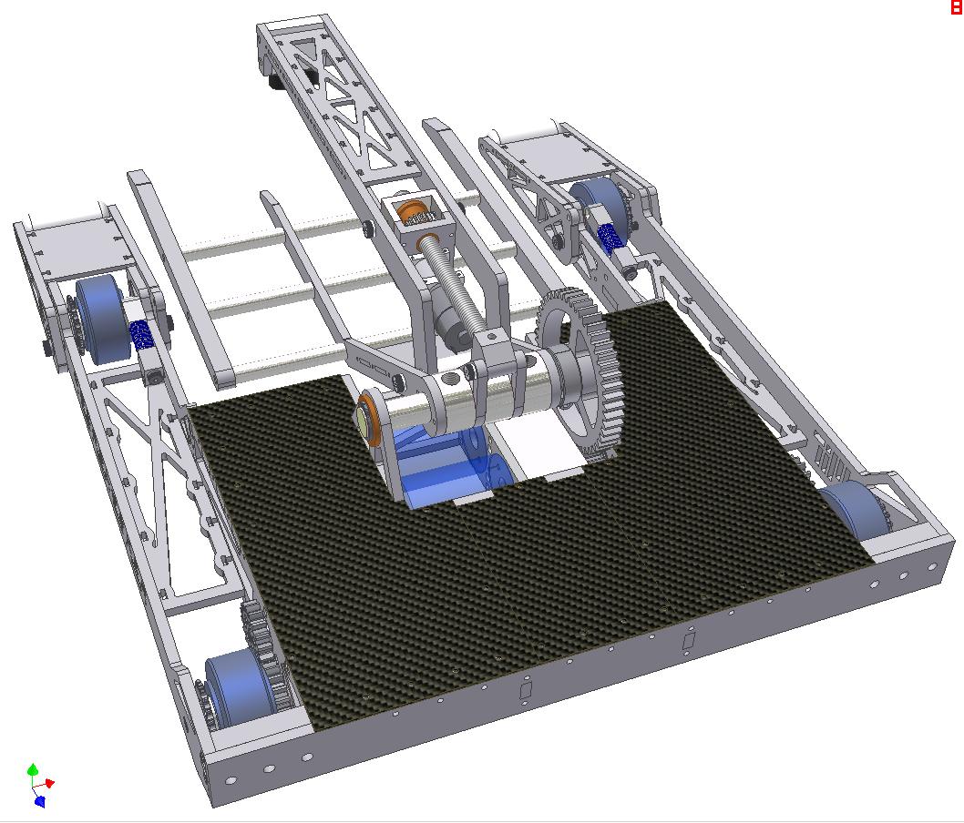
In the last Überclocker episode, we left off with the last known CAD drawing of the whole robot.

This was designed back in November-December of last year. Now that 2.007 has come and gone, and I’ve explored building puzzlebots more, I hate this design. There’s too much unsupported sheet metal. Too many things being bound together with a compression member that are otherwise supported, too many parts, and too many awkward assemblies. The overarm mechanism is also shady. But at least the clock logo on the top is cool.
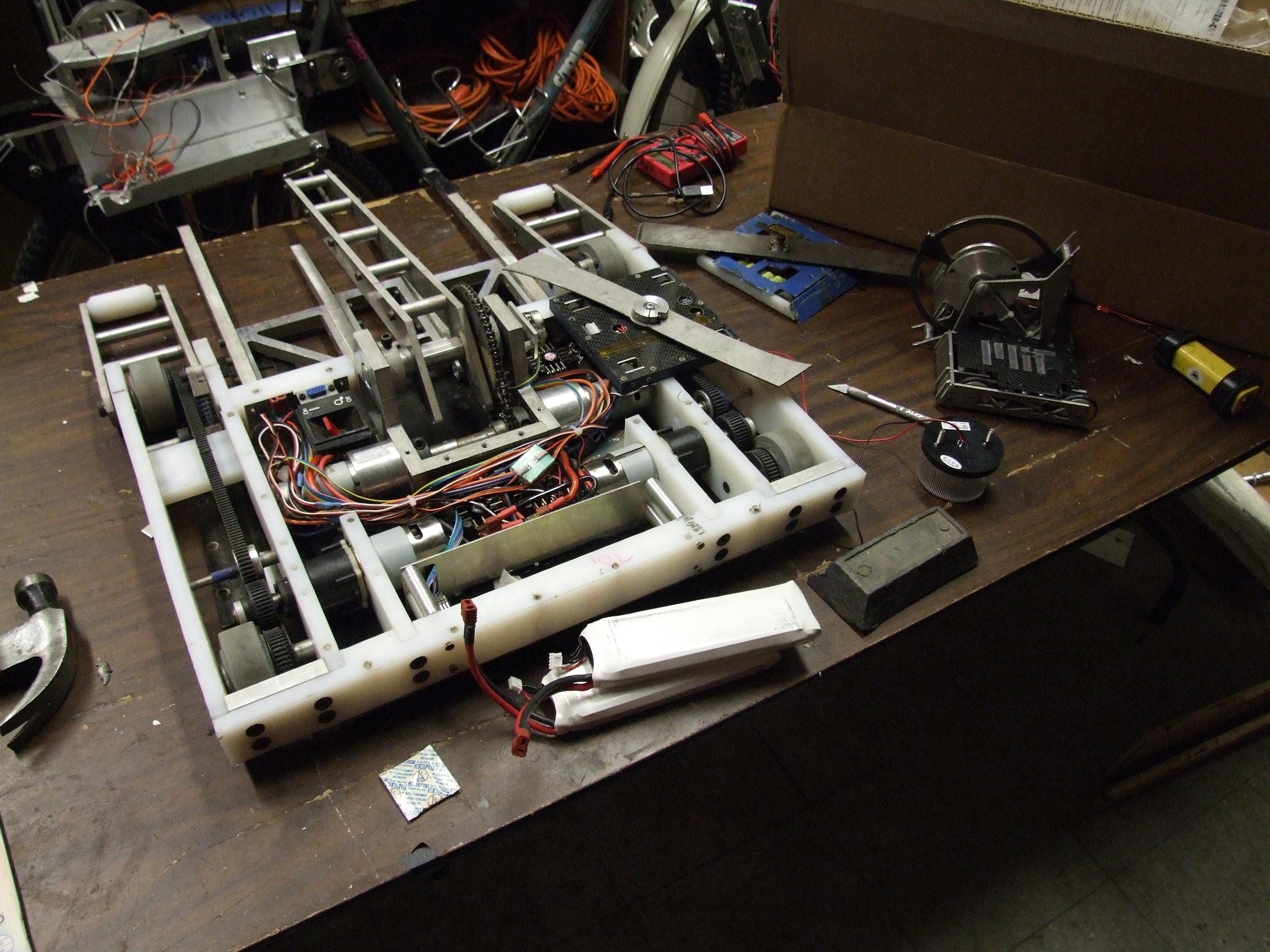
Nevertheless, I needed to use material more effectively, so I opted to redesign the frame with large, T-nutted members alongside interlocking tabs.

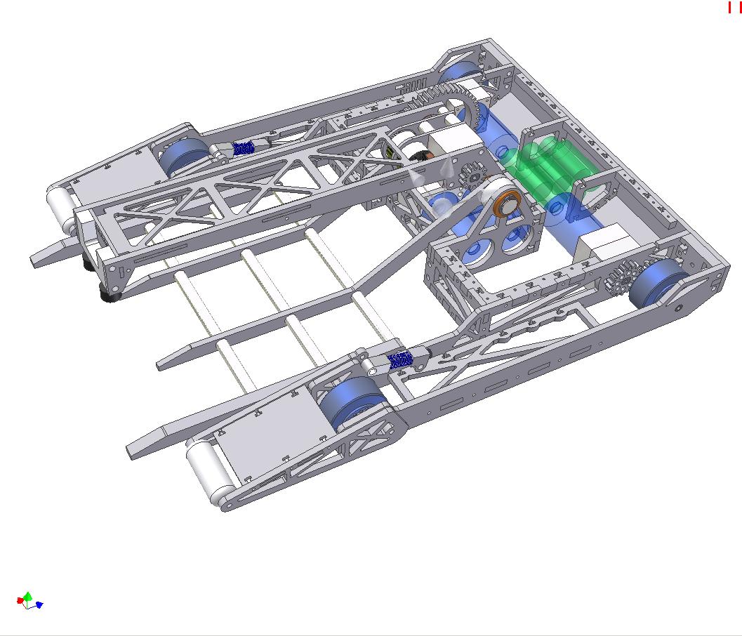
So here’s a picture of the rework in process. The drive base part count was reduced 25%, and this goes together alot more like my other robots. Otherwise, everything remains the same – gear and chain-based 4 wheel drivetrain, and the Integrated Dual Frankenb0xen™.
I elected to switch from 4.2AH lithium polymer batteries to a small cluster of A123 26650s. A123 cells are renowned in the model and hobby robot industry for almost absurdly high performance (pulse discharges up to 60C and continuously to 30C or more) at the cost of a bit of energy density. The biggest upside is their comparative nonfinickyness.
The pack configuration I chose is 7S1P, or about 25.2 volts charged and 20 volts discharged. This is the closest match to my existing 22.2v electrical system.
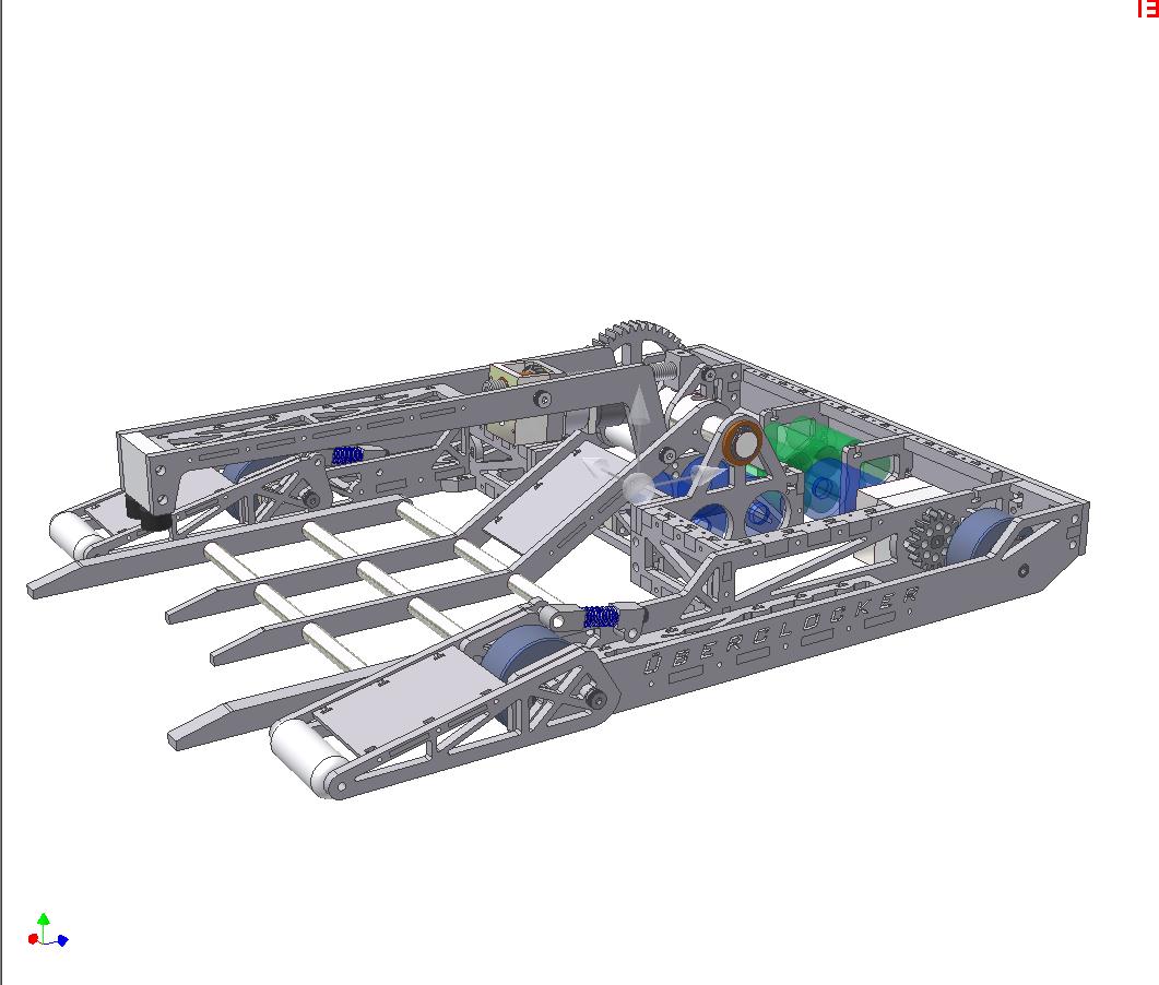
A leap of faith later, and the bot is mostly done. The overarm is still from the last revision and is just there for visual effects.
The fork has been drastically simplified. Instead of cut plates, I decided to go with plain standoffs retained with allthread or long bolts. It turns out that using these standoffs with the binding pressure of good bolts is actually stiffer than the spans of aluminum I have been using in the real bot and the designs. It has the highest stiffness-to-weight ratio of the options.
But now it won’t look as badass.
The new overarm designed. Looks kind of like the old one, eh?
It’s slightly narrower and not as “huge”. The width is because it precisely fits the clamp actuator in the middle with little room to spare. Also, the overarm no longer hinges from the main fork axle, but rather is a fully independent assembly. This will save assembly time and simplify field repair, since I won’t have to rip the entire front half of the robot off to service one part.
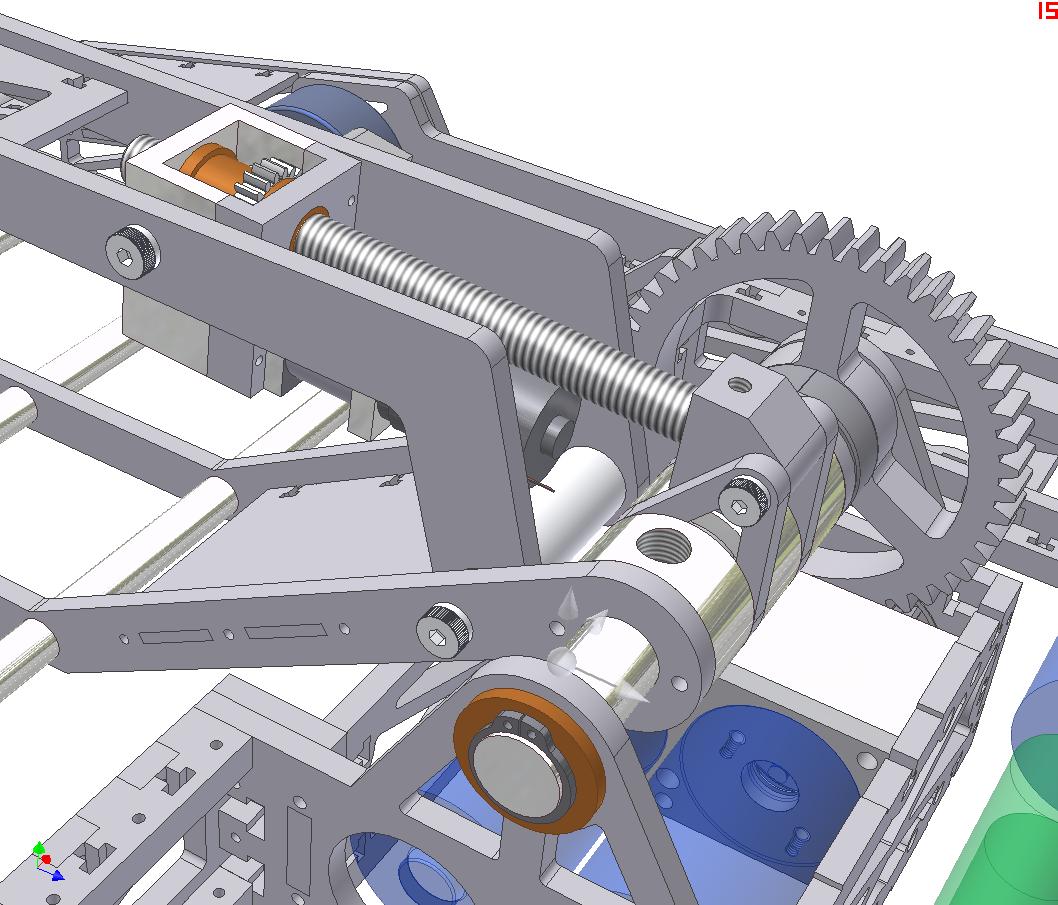
And here’s the clamp actuator. Gee, it looks kind of like the last one.
That’s because it is. But it’s better. And won’t suck – I promise.
The difference lies in the fact that this one is substantially larger. It uses a Banebots 28mm planetary gearmotor driving a leadscrew nut, which rides up and down a stationary and larger leadscrew. While normally I shy away from Banebots equipment, their newer motors seem to be decent and the output shaft won’t be taking any direct shock loads, only gear torque. They’re also available in a reasonable voltage, unlike the next best option (screwdriver motors) and aren’t enormous (drill motors).
The leadscrew will be firmly (read: either threaded, pinned, or set-screwed-with-big-flats) embedded in its own hinge block, so we won’t have the problem of the clamp arm falling off and jamming the leadscrew under the robot.
I vouched to retain the leadscrew design because of the degree of isolation it gives between the arm being forced upwards and the force on the motor. The clamp is an enormous moment arm for anything on the end to push against, and if there were a direct 1:1 rotary coupling between the clamp arm hinge point and my actuator, I could very well blow something up.
Additionally, the fork is attached to the main shaft using Ginormous Death-screws. Like set screws, just more hardcore.
On the other hand, having the leadscrew means the only way the mechanism can be defeated is if the leadscrew bends, the threads in the nut strip, or the arm breaks in half. I’m ruling out the possibility of 5/16″ diameter hardened steel shoulder screws shearing. One of these shoulder screws might be replaced by a nylon or Delrin rod as a last-ditch overload lifesaver.
The frame, demonstrating gratuitous T-nutting. I purchased square nuts from McMaster expressly for fulfilling this role. It’s like an end-tapped hole, but there’s no drilling, tapping, or setting up the part which is inevitably impossible to hold properly as you drill it.

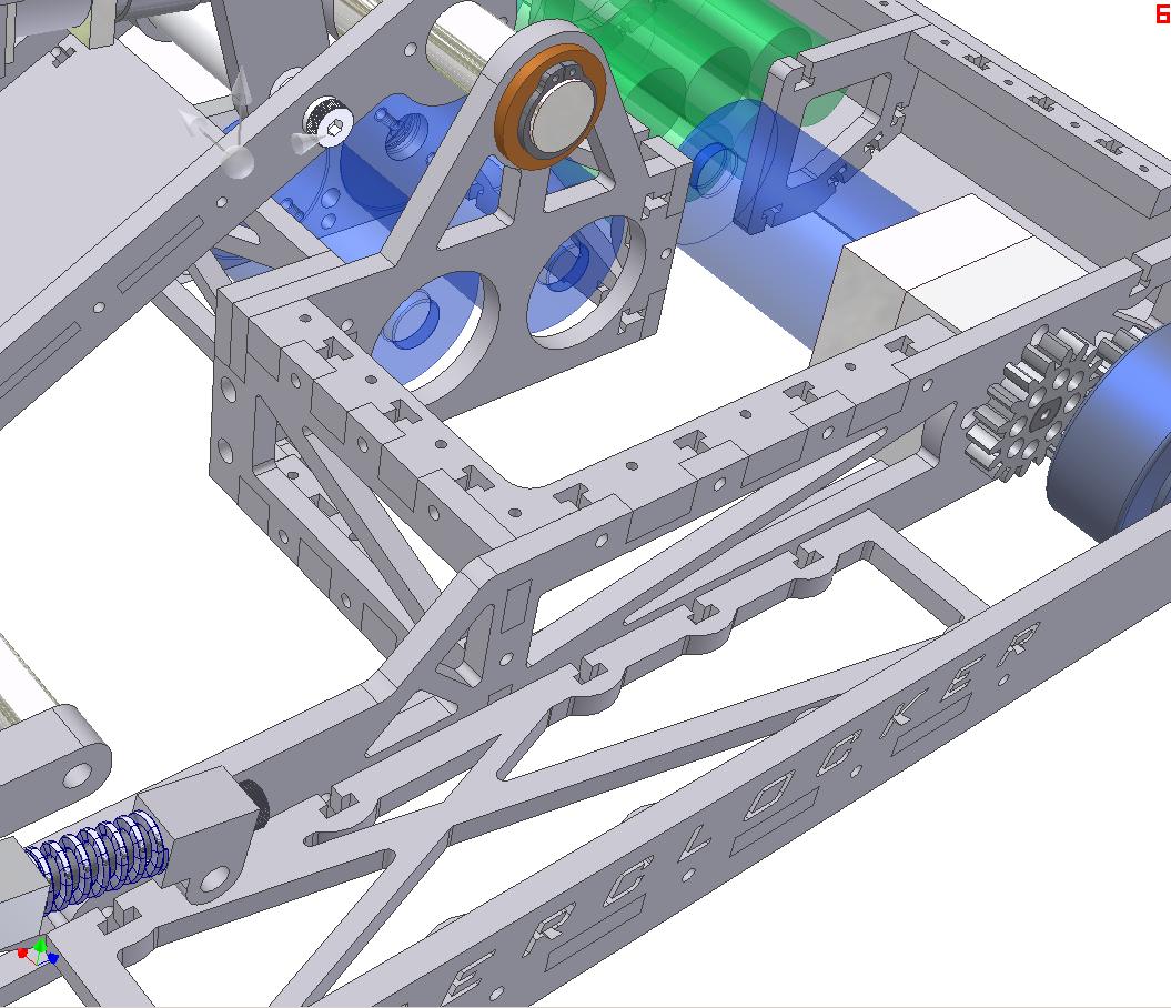
Another time-saver on this robot was my discovery of shaft collars with bolt circles. Seriously – shaft collars with threaded bolt holes in them, to attach something to a rotating shaft. That’s called a hub. If you only tighten the shaft collar a little bit, it’s called a clutch. If you combine the two, it becomes a torque-limiter.
So I have simplified the Great Cone Clutch Clusterfuck to use this one awesomecollar. Currently, the main fork shaft uses two shaft collars acting as clamps over a split tube to transmit torque to the fork, to great effect.. I expect a direct connection to be no different.
Covers. The clock logo is not yet laid in, but the main feature of the top plate is visible. It’s actually three plates. The center one is directly over the battery pack, so I can get to it and swap packs very quickly. Because the pack is only 2.3Ah, I’ll probably need to change batteries (as opposed to just charging in the bot) for quick turnaround times.
Either way, removing 9000 screws to get at one loose wire in Uberclocker was too much of a PITA to repeat.
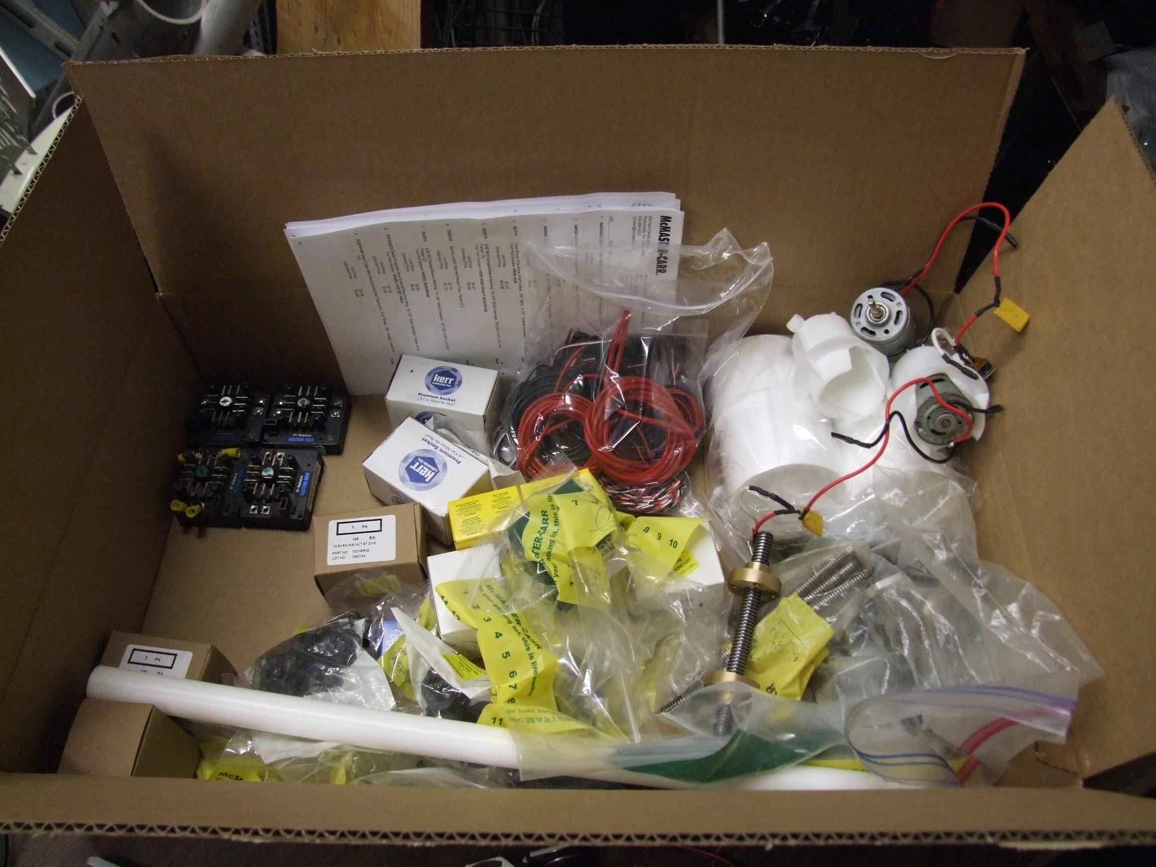
And so it begins.
You’re looking at about $300 of McMaster hardware and $200 of other crap (wiring bits, controllers, motors). I don’t know how these things got so expensive (damn economy, etc.), or maybe now I’m just building real robots or something, because nothing I used to build cost this much.
Maybe this is just a symptom of my encroaching laziness. Hey, why build things when other, smarter and more productive people have figured out a way for me to buy stuff from them?
I got a nice enough deal on the 4 Victor 883s that I’ll probably end up using them in the bot, even though they are enormous and will take a pretty good amount of stuffing.
It’s time to excavate the robots and prep them for rework. For the past year or so, the bots have been on the bottom shelf of a multi-deck pushcart upon which I have heaved all my spare parts, random cruft, metal billets, and half-baked projects. They were really really dusty.
I’m actually considering keeping most of Überclocker 1 assembled, because there’s technically nothing wrong with the bottom half of the robot. The frame and running gear are still functional, and technically the lift gearbox still works – one motor just smells weird. Since I’m not really reusing any parts at all, it would make a good “audience bot”. Hell, if the upper clamp arm is removed, it works fine as a spatulabot.
Alternatively, anyone want a half-robot? I wouldn’t mind selling the current build to generate more parts money for the current one. Sans receiver, but including 2 Victor 883s, a Victor 36HV on the fork motors, and the LiPo batteries (with external balancer connection using a DB-9 connector).
The chassis metal is on the way, and with my waterjetly ways, the frame ought to be assembled by next week. Kind of good, considering next week is the last week of July.
Bot…on?


