


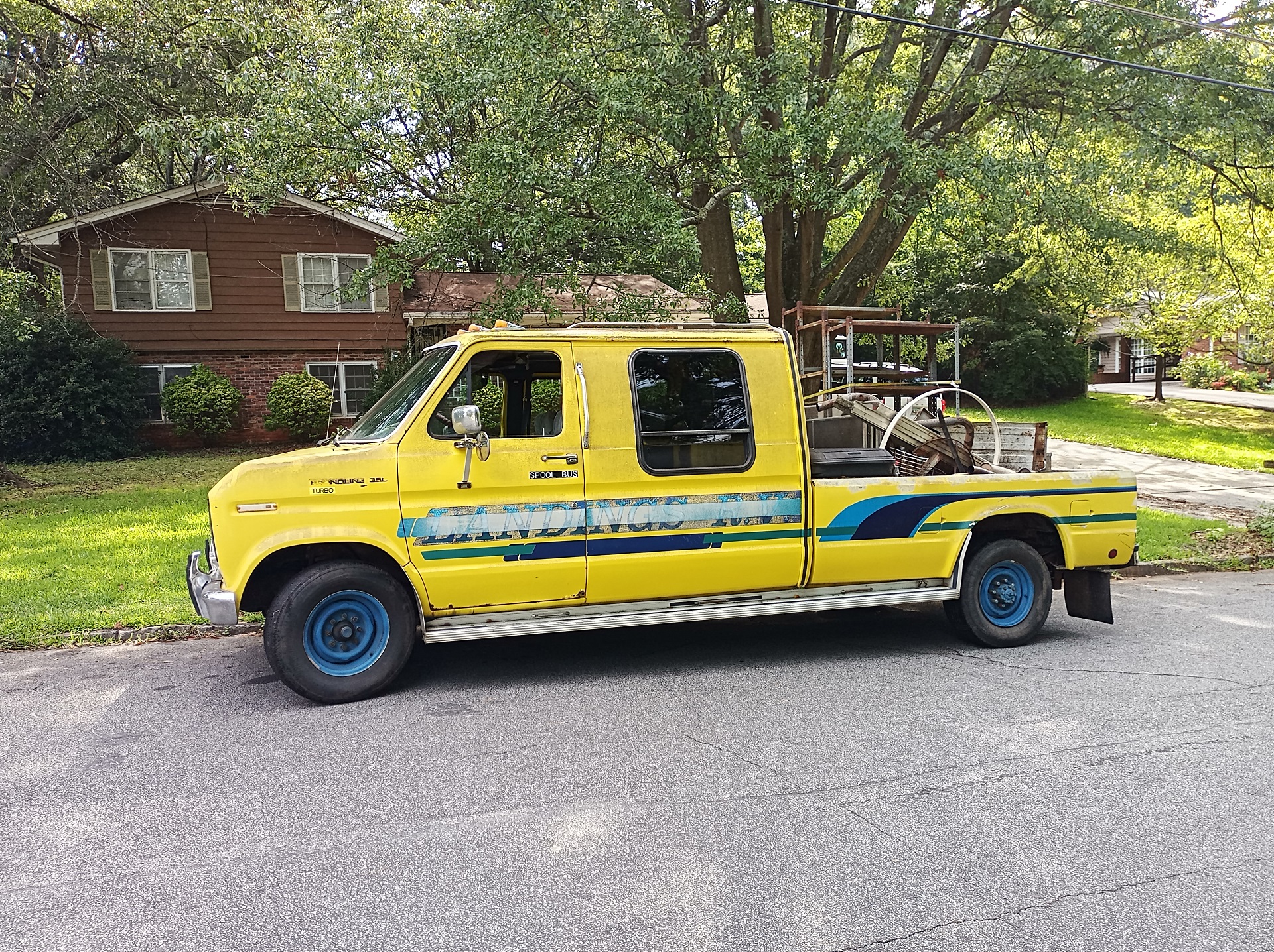
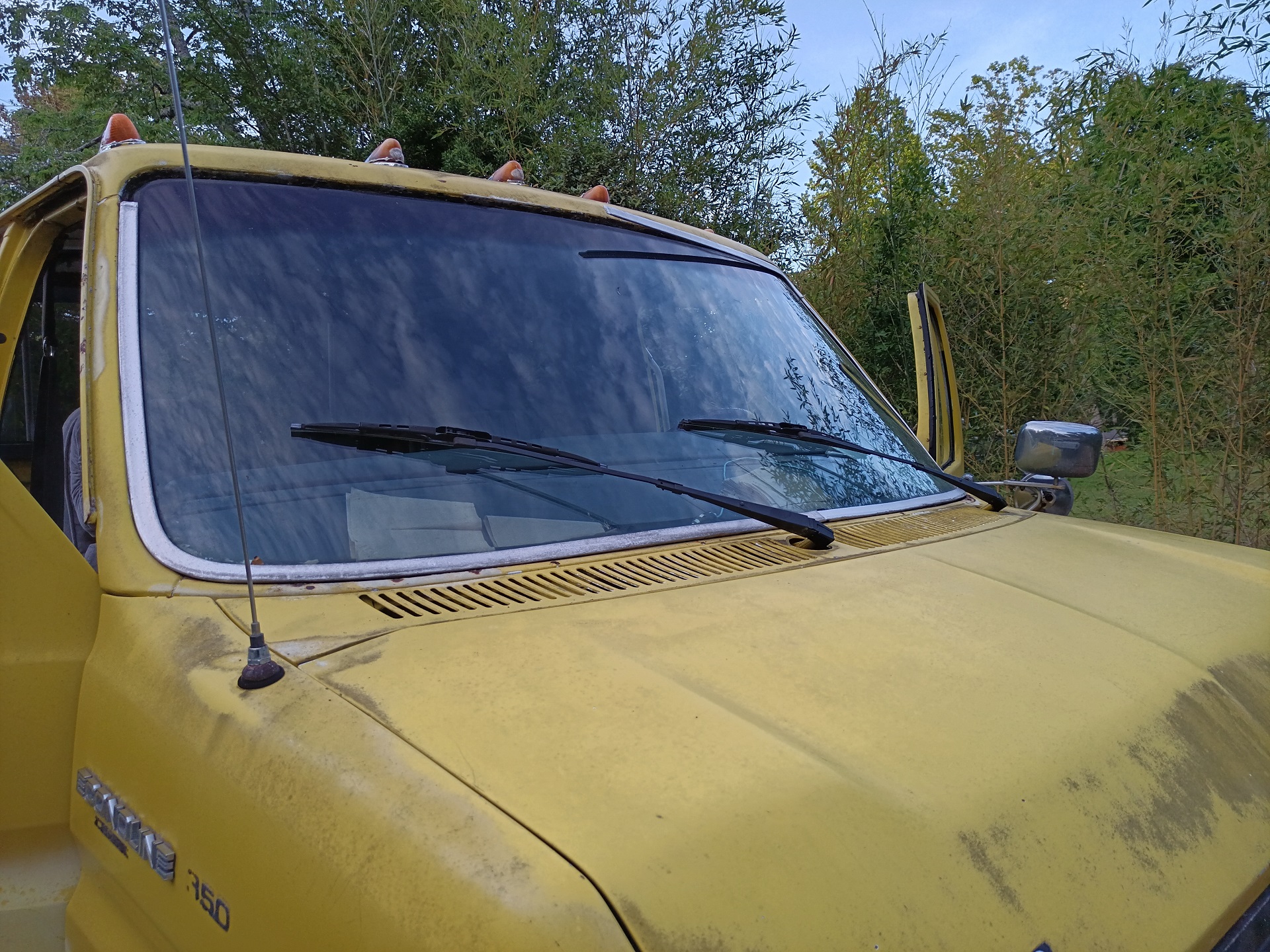
Haven’t heard that name in a while, right? It seems like after renovating the fuel system way back in 2021, Spool Bus just kind of vanished off this website, except for appearing as background set in photos occasionally. That is because Spool Bus became sort of an unsung hero of the Old and New Robot Trap House: it was principally in charge of all the 𝕿𝖗𝖚𝖈𝕶 𝕾𝖙𝖚𝖋𝖋:
After all, can’t have my white elephant doing any work or something. Once the summer’s worth of mechanical work was completed, Spool Bus was simply a well-running and driving truck, albeit one with many peripheral functions missing or worn out. But that means I didn’t feel bad chucking scrap metal (above) or rocks and concrete waste (below) into it.
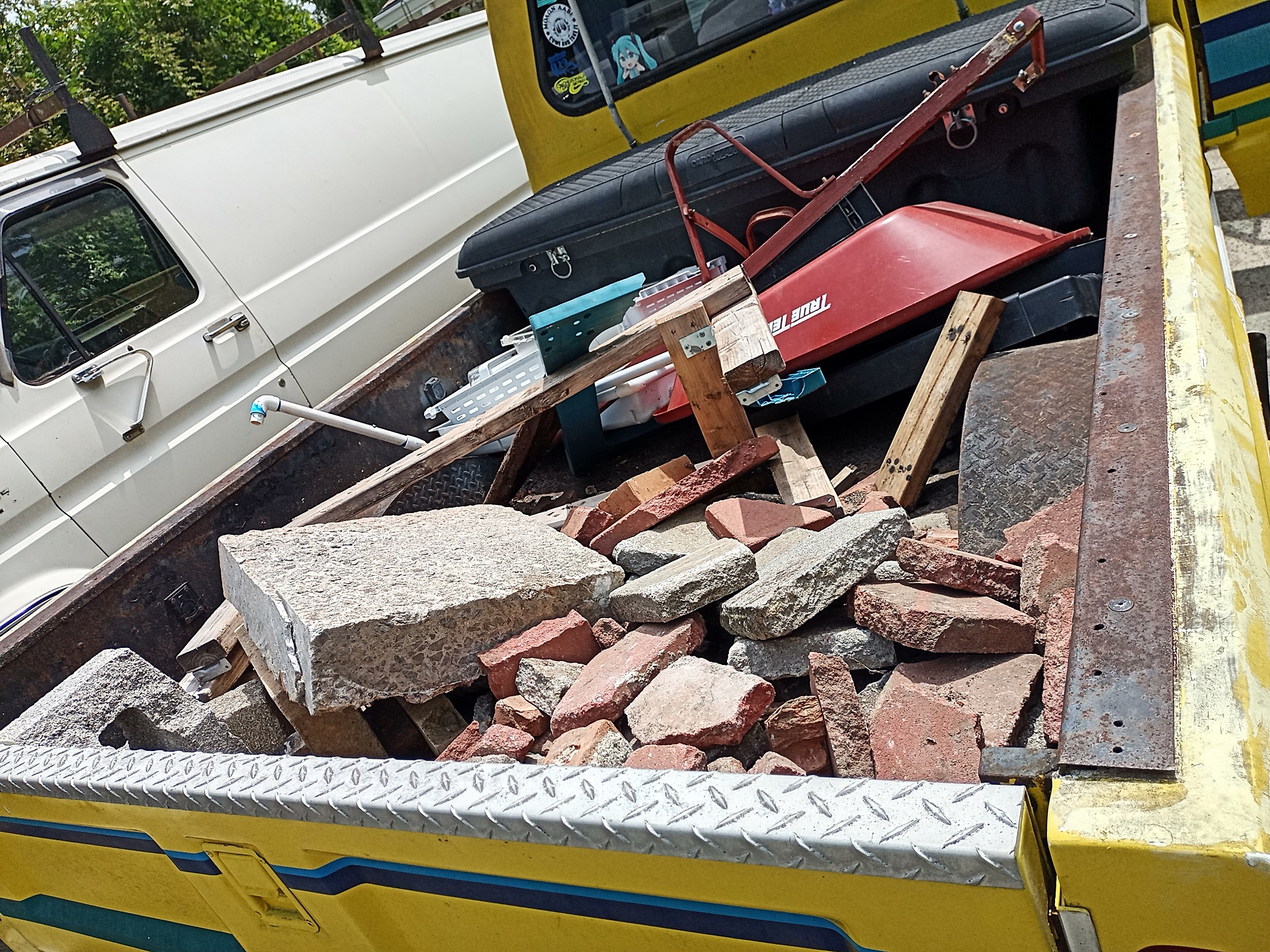
It is kinda nice to have something you don’t really feel bad subjecting to this kind of “throw it in and send it” treatment. Like, there wasn’t really anything I could do to Spool Bus to make it consummately worse than it already was, with gaping floor rust holes, almost every dashboard instrument dead, and a bed made of 3/16″ thick plate steel. And with that mechanical service front-loaded in 2020 and 2021, my usage cases were really so light-duty for the platform that I barely even touched it for all sorts of maintenance since.
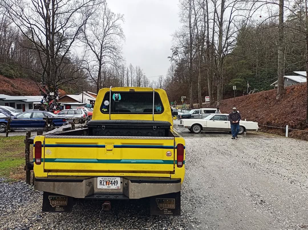
This isn’t to say Spool Bus was only pulled out once in a prime number collision for some menial task. It not only participated in meme recoveries including, in this very year, the most arduous van recovery mission I’ve ever taken on (More on that story later), but I also regularly brought it around to local car shows… or just took it to the Tail of the Dragon for fun while chasing the Lemons Rally.
But gradually, the grievances did pile up. When I said “nothing in the dashboard worked”, I meant it. It had no turn signal pilot lights (though the blinkers and lights themselves worked), and the oil pressure and thermostat gauges were inoperable.
The wipers only ran very slowly if I hit a pothole in the correct way, a sign of the motor being just totally spent.
The HVAC blend selector was stuck on heat with the lever broken, so I had the choice (when the blower motor was actually working, needing a different pothole impact angle to work) of Hot or Even Hotter.
The vacuum system was so weak that said HVAC system could rarely get out of defrost mode, and I only had one pump of power brake assist available. This probably meant the brake booster canister was bad as well.
The front fuel tank’s feed line probably had a crack in the hose, because it pulled air instead of fuel and would aerate the fuel system nearly instantly if I switched to the front tank. So I really only had the rear tank available (whose gauge only reads below 1/4th, else it reads zero).
Let’s just say it was just getting really bad and uncomfortable to operate on the regular. So, in May, before the weather started entering truly hot and steamy territory, I decided to embark on the LONG HOT SUMMER OF SPOOL BUS, a quest to eradicate as many of these problems as possible.
At minimum, I needed a working HVAC system and wipers. Even if the air conditioning is toast, the Econoline’s front vents are not wimpy and at least lets things be survivable (Mikuvan’s front blower motor is very weak with wear/age, making it pretty deathy to drive in summer besides being deathy to drive in general).
So, I focused on those problems first. I pulled a wiper motor from a junkyard van many moons ago because it was right in front of me, and the intent is to just change it out while keeping the old motor for a future rebuild, as chances are high it simply ran out of brushes.
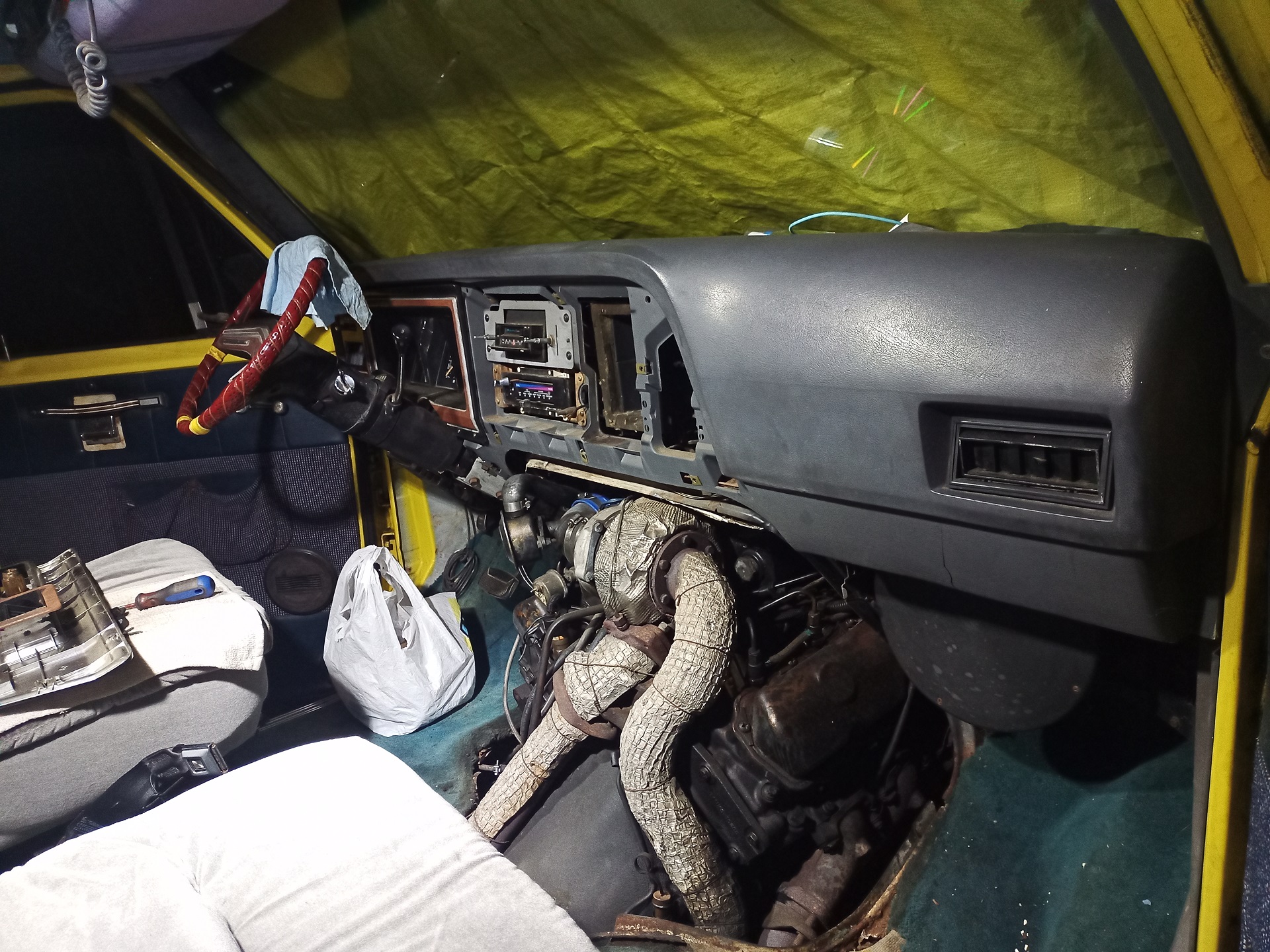
To do the HVAC selector/blend door system, I had to do a deep dive and take apart the entire thing from both ends, in order to reach and inspect the broken Bowden cable that connected them. So back to the scene I’ve been presented with many times…
Like I said before, I had no beef at all with how Spool Bus drove. Arguably it starts and runs better than Vantruck does (I have long suspected that this is not its original engine, and it had a proper rebuild or reman engine dropped not too long before it went in-op), and the little Banks turbo adds like 7 butt-horsepower and convincing sound effects. But this is definitely the layout that made me try out the low-mounted twins of Snekvan, then Vantruck, through Operation IDIocracy.
Knocking the dashboard down was easy enough, although the (sporadically working) radio is annoying because all the knobs have to be removed first to unscrew its faceplate. The HVAC selector pod is below the radio, so removing it is required.
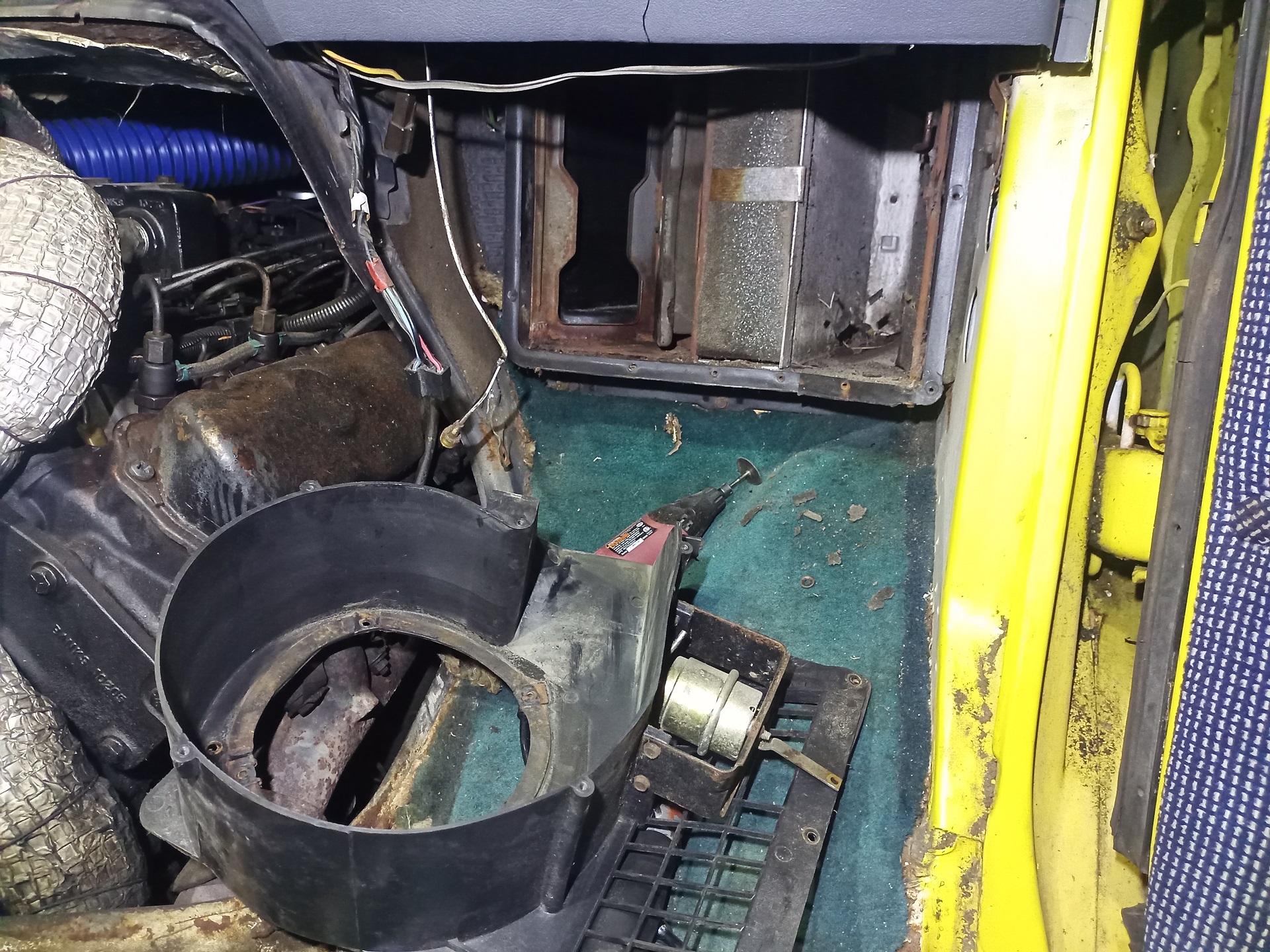
On the passenger side, removing the blower motor and its cover is just a few screws. This allowed me to peek into the absolutely filthy poop-encrusted blower box and heater core housing.
That foam covered door is what moves when the temperature lever is pulled, and I think at some point it might have become stuck and then the cable broke internally. That, or the mounts cracked off. Either way, it was free to move at this point already.
The blower motor and fan wheel dismantled well for being rusty and 40+ years old. As I suspected, the motor simply became brushless over time. I had a replacement I bought a while ago, so this pile of motor got put in a Giant McMaster-Carr Bag for future rework.
I mean, all it really needs is brushes and maybe some oiling of the bearings. They’re just too simple to truly die.
To get to the Bowden cable that moved the flap, I had to remove the blower housing, which fortunately was just a couple more screws but required very close-quaters van combat above where the dashboard pad covers everything. Nothing but a few plastic-threading screws here though. The Dremel was needed to cut new drive slots into several internal panel screws which were thoroughly rusted.
(This was also a great chance to vacuum, air blast, and somewhat pressure-wash this whole box out because who knows how many animals have pooped in it over the years)
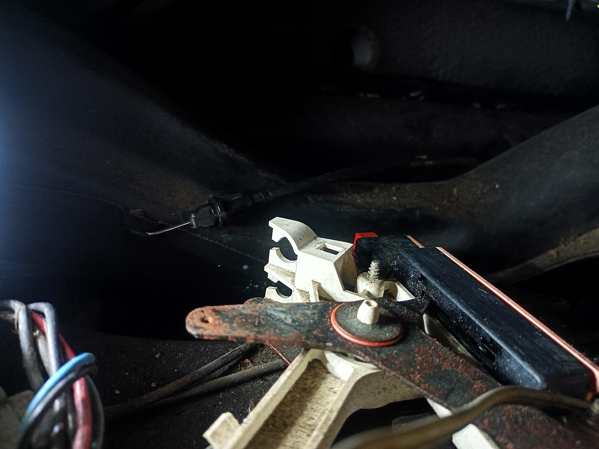
Interestingly enough, the Bowden cable was still fixed and working on the blower box end… but on the selector side, the Z-bend that used to connect it to the lever was snapped off. So, it might just have been fatigue over time.
The problem was that the small plastic snap that anchored the cable housing (so it could do the Bowden push-pull thingie) was also cracked apart. This meant the cable housing couldn’t stay in place any more.
Nothing a large, healthy blob of Sugru couldn’t remedy. At the same time, I noticed that the selector valve itself was slowly cracking open at the seam between the black and pink housings.
This probably helped explain why it would barely switch over, as it would just be a massive vacuum leak. I solved this by cracking it open the rest of the way, then putting a big ring of CA glue around the former factory joint and clamping it together.
My solution to the broken Z-bend problem required a big of digging into some very old parts bins…
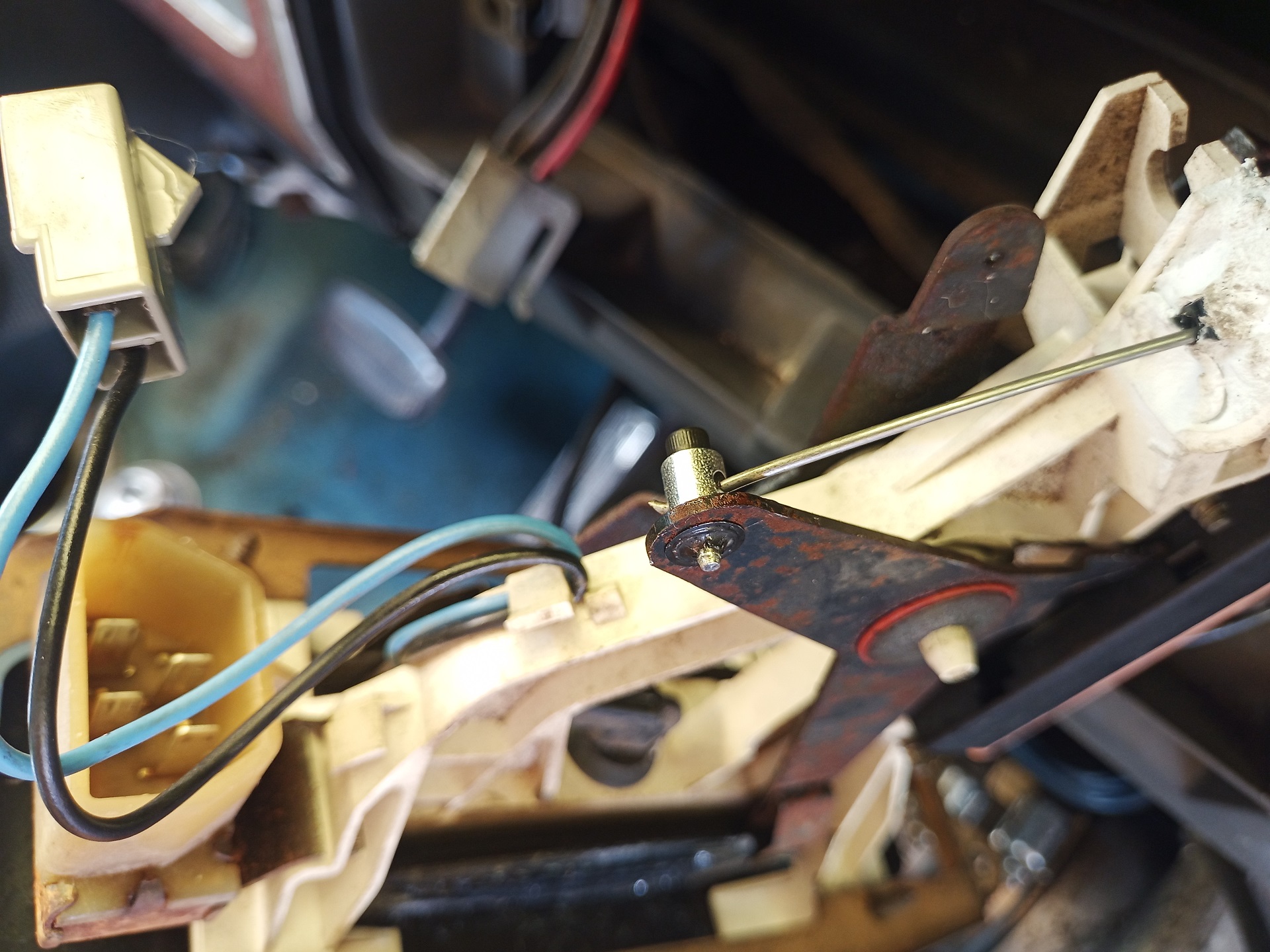
I was just going to use a model airplane pushrod connector. In doing this, I sacrifice about 3/8″ of travel off the lever, so “Mostly Hot” is fully hot, but this worked perfectly on the cold (a.k.a Still Mostly Hot) side.
Getting the Bowden cable housing screwed in again on the other side, though, was one of those “double blind” van wrenching operations.
The first blind is visual because you can’t actually see what you’re doing because you have to face the other direction for your arms to bend the correct way. The second blind is tactile because you have to feel for where the screw hole is while simultaneously making sure the little plastic tabs line up, and all of this operation is occurring near where your fingers’ Jacobian matrix is as singular as you are.
But luckily, after enough wiggling, the Bowden cable was anchored on both sides again, and I regained control as to whether Spool Bus blew Warm or Warmer air into my face. As I said, the lever stops about 3/4 of the way up the Hot mark, but that is nothing a strip of black Gorilla tape can’t fix by visually blocking the rest of the way!
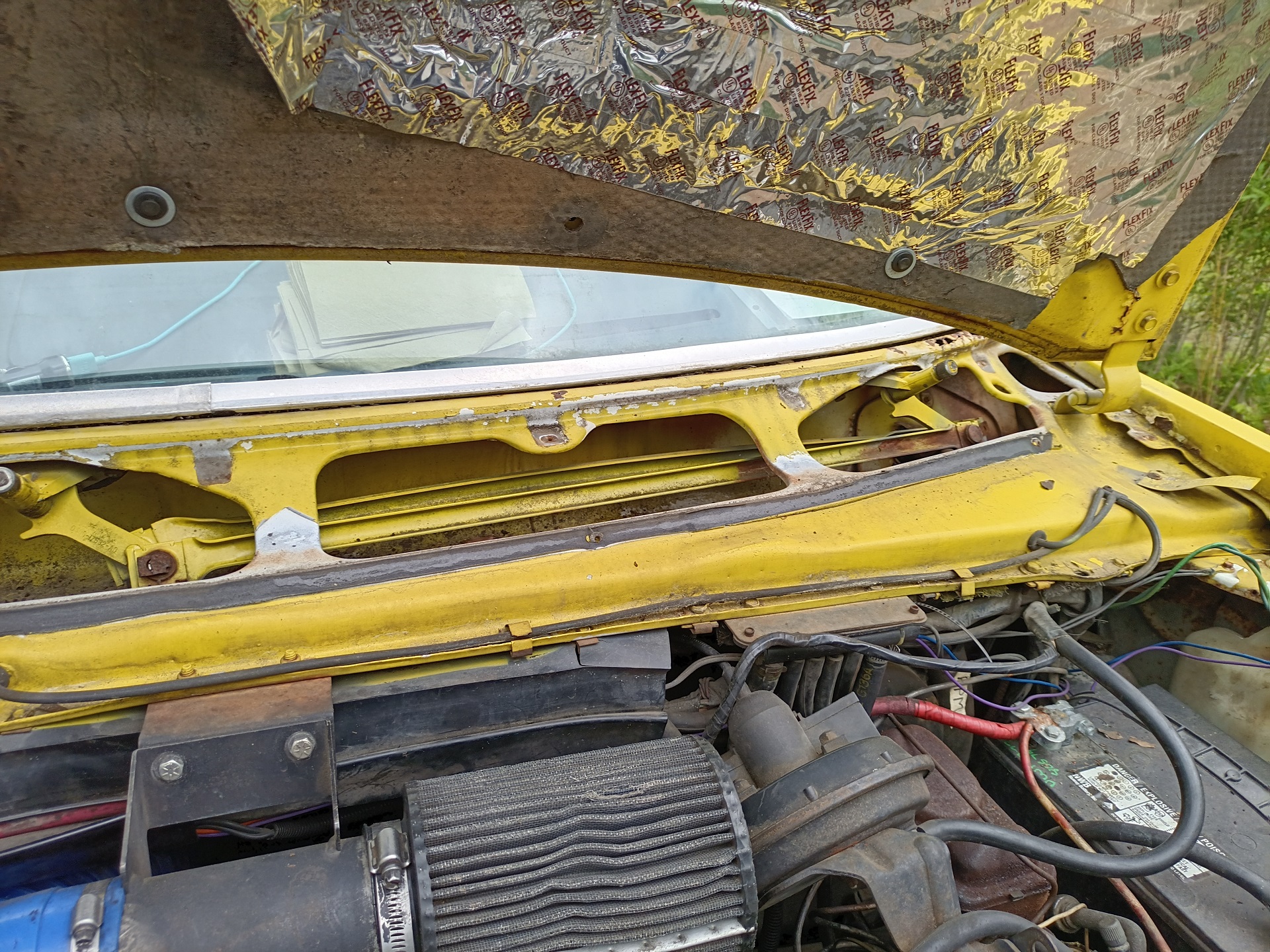
Alrighty, next task. It’s windshield wiper time! To remove the motor, I had to dismantle the windshield cowling which necessitated some Advanced Fastener Extraction techniques in some areas because the 40 year old Phillips head self-tapping metal screws had basically become smooth-head rivets from corrosion.
After the cowling comes off, most of the wiper mechanism is immediately accessible from the top.
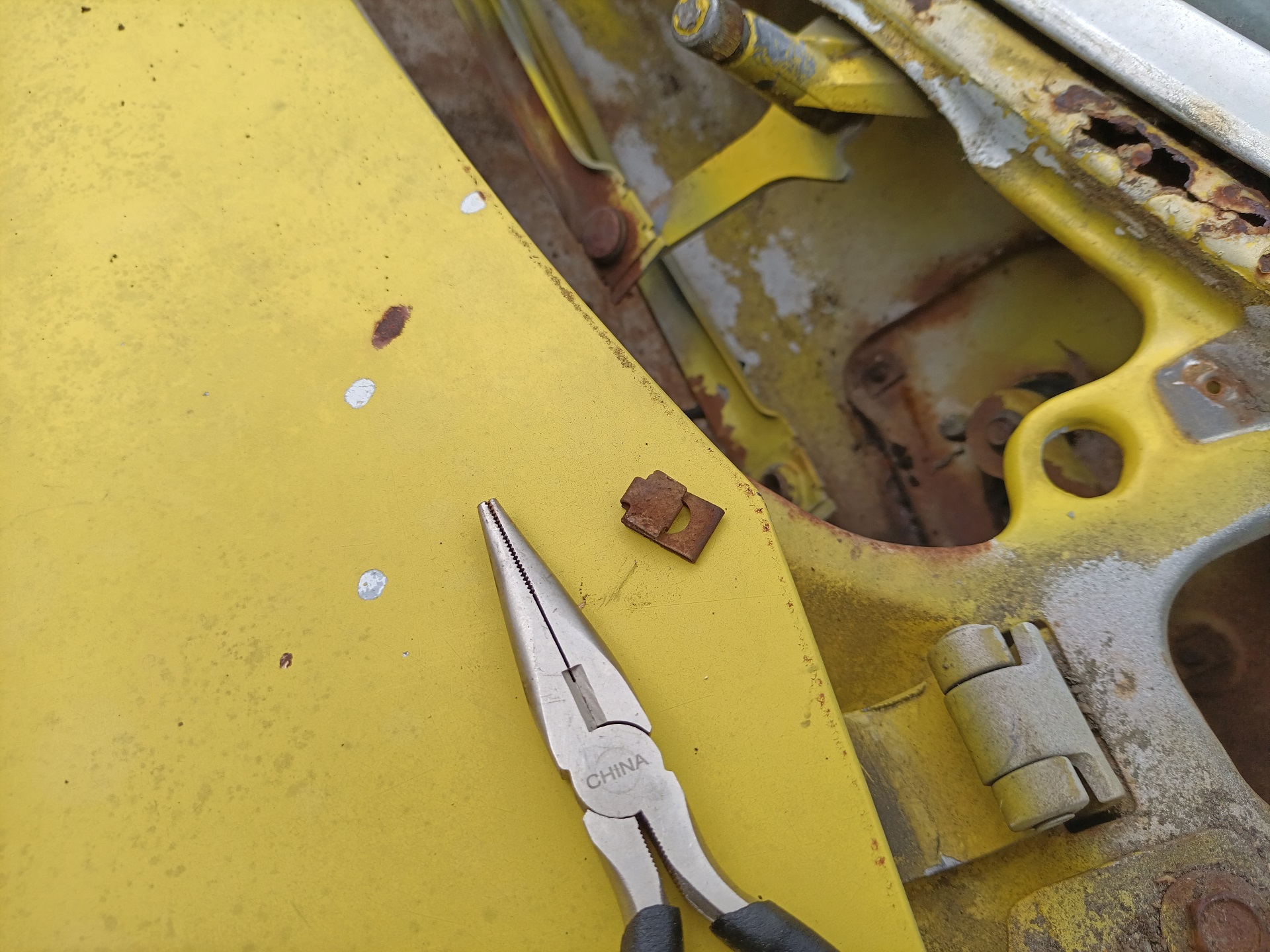
The linkages and bushings were in surprisingly good shape without much slop. They’re held together by these funny little clip-on retaining rings, which were all on the borderline of disintegrating – if they do vanish, I’d just replace them with regular snap rings or E-clips. I took both of the linkages apart and cleaned and regreased them anyway.
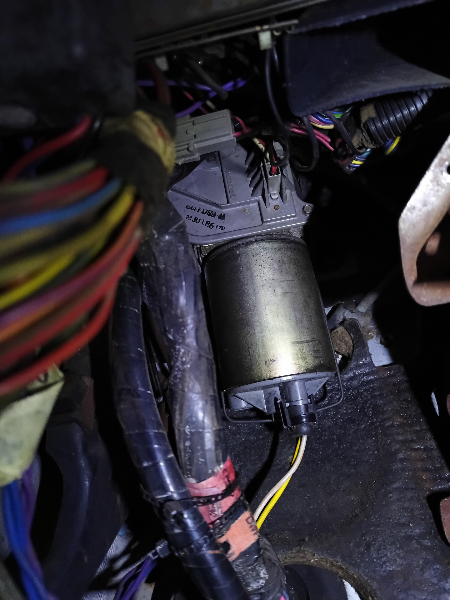
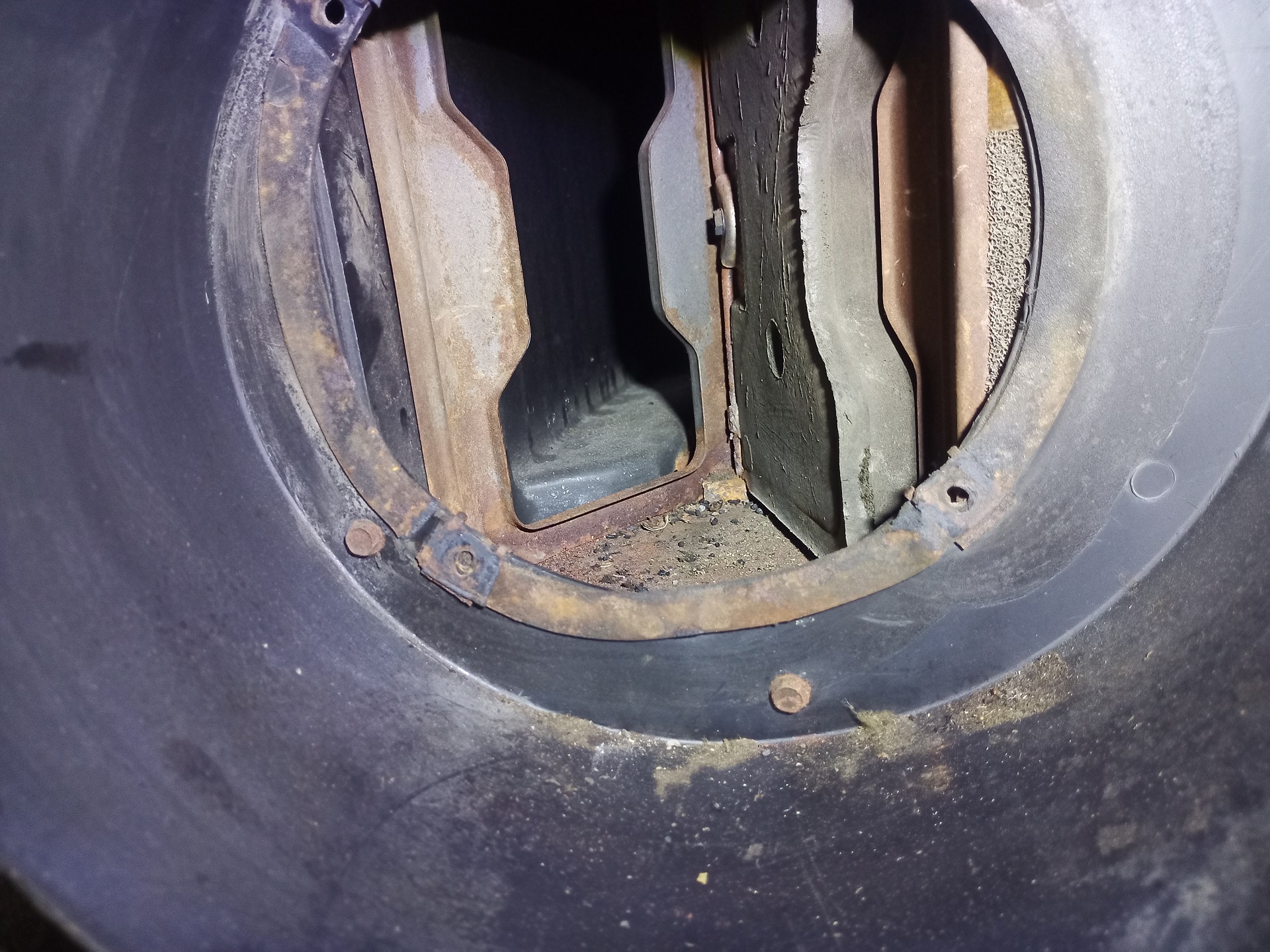
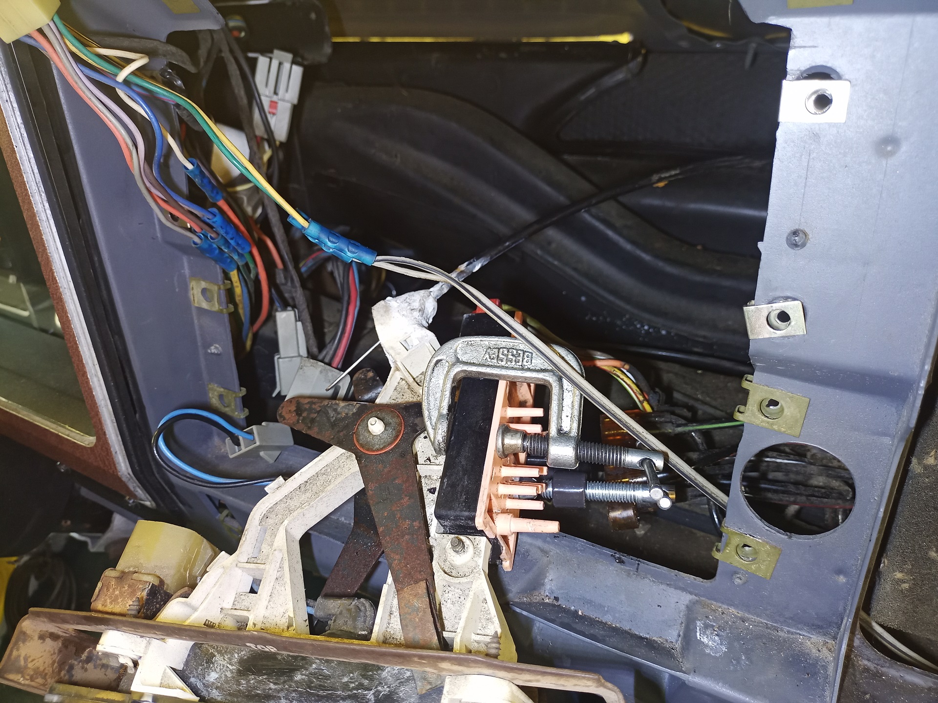
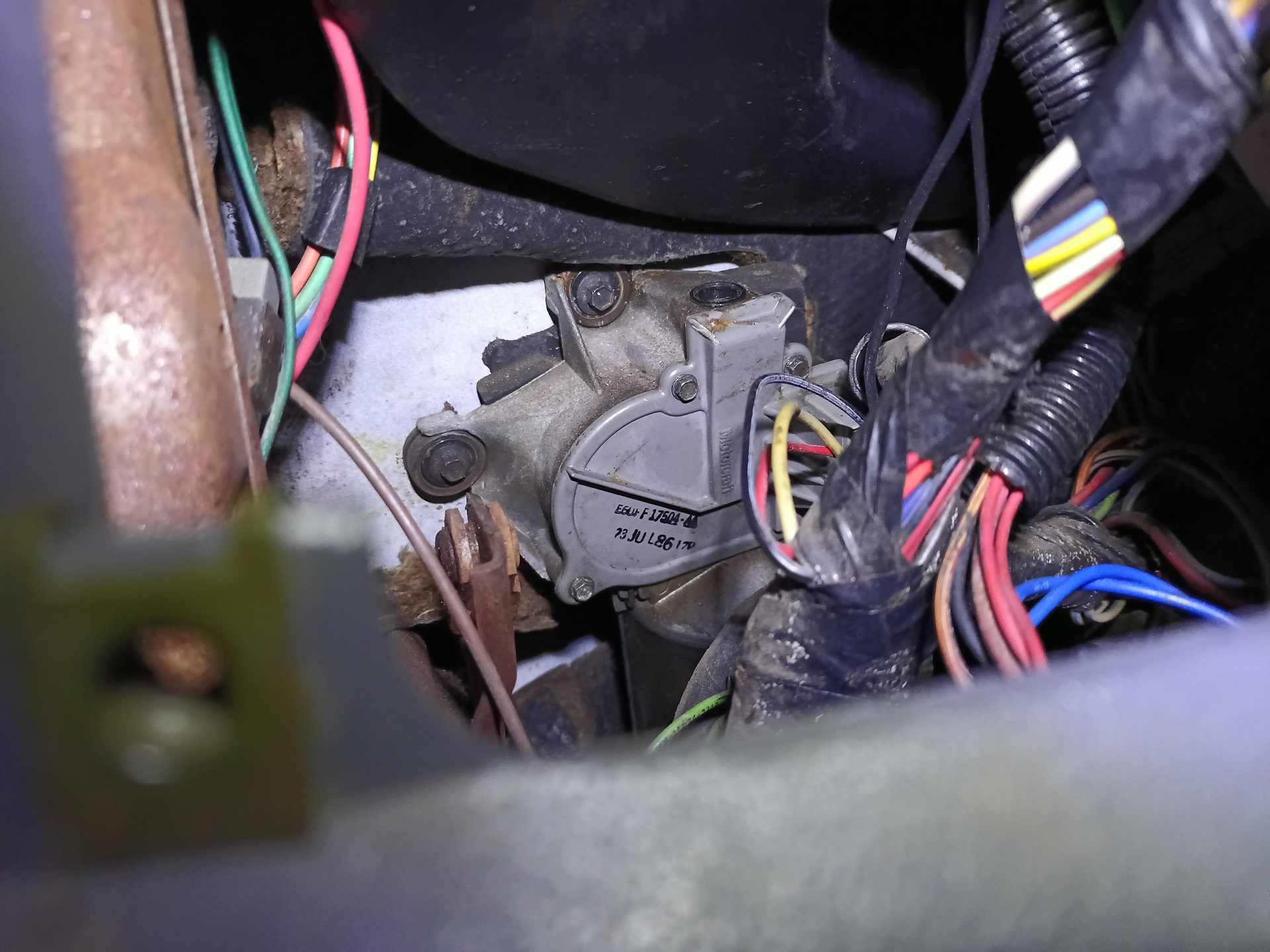
The motor itself is removed from the inside underneath the dashboard. As you can see, there’s a pretty clear (for a van) path to getting its mounting scr….
No, just kidding. This is what the view ACTUALLY looks like when you start.
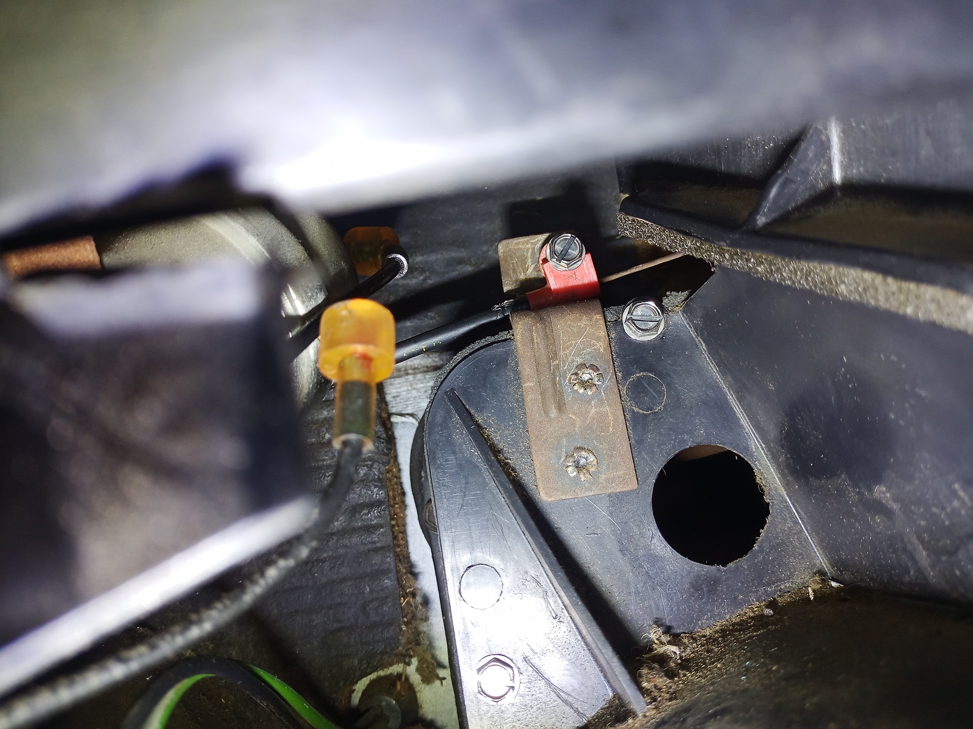
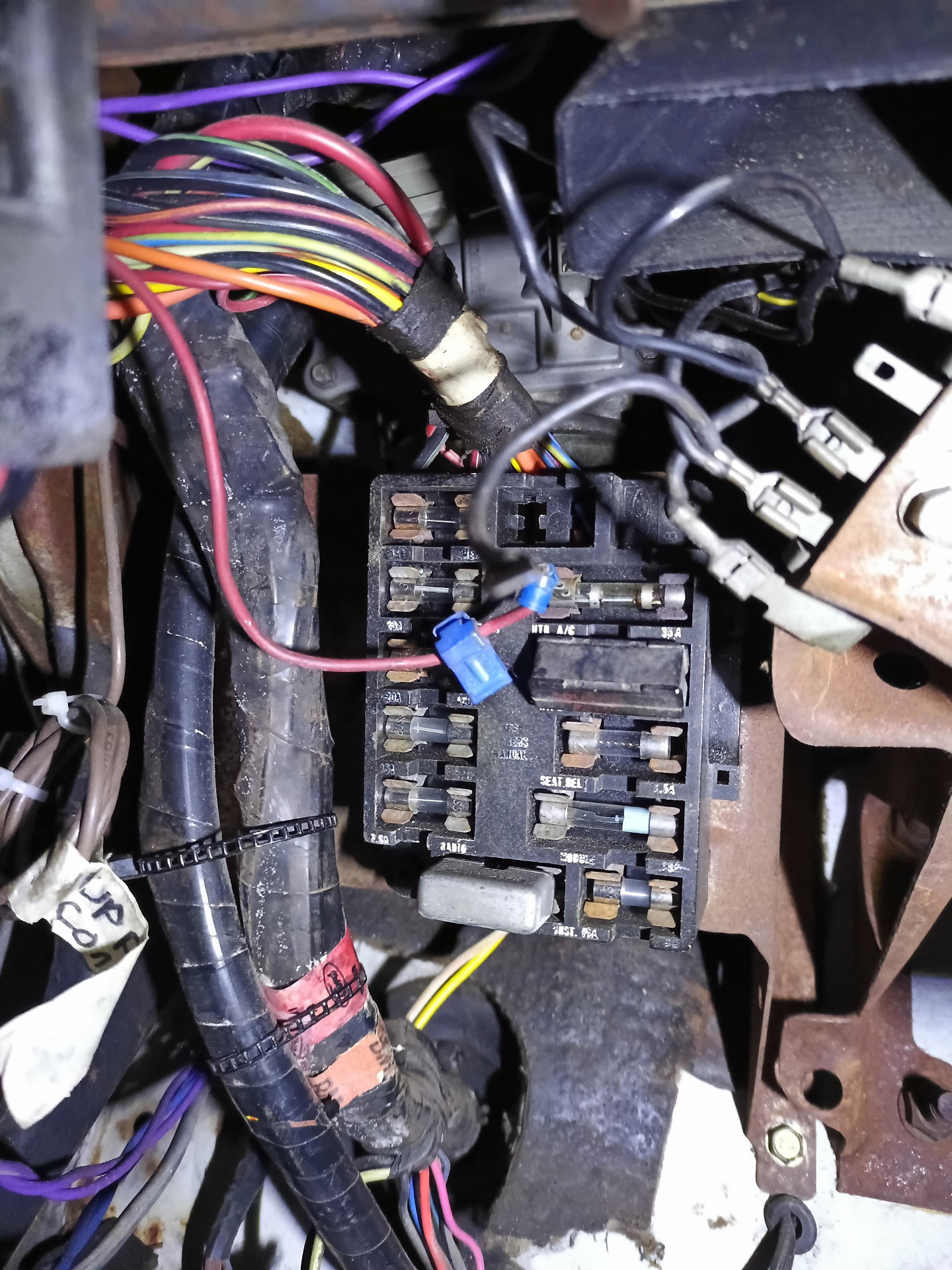
The shop books suspiciously skip over the fact that you have to dismantle out the fuse block, its little mounting bracket, the ground fanout bracket (on the upper right), and disconnect the brake light switch and cruise control vacuum switch. And, on top, the left side dashboard panel has to be removed and the ventilation duct behind it as well, which means you’re disconnecting the headlight combo switch and wiper switch too. All it says is “Remove Motor”.
Y’know, I’m starting to think I thought this was an easy job because the junkyard van already had all of those things stripped out by someone… so I was just looking at the wiper motor, going “Ah, yes, there’s nothing in the way!”
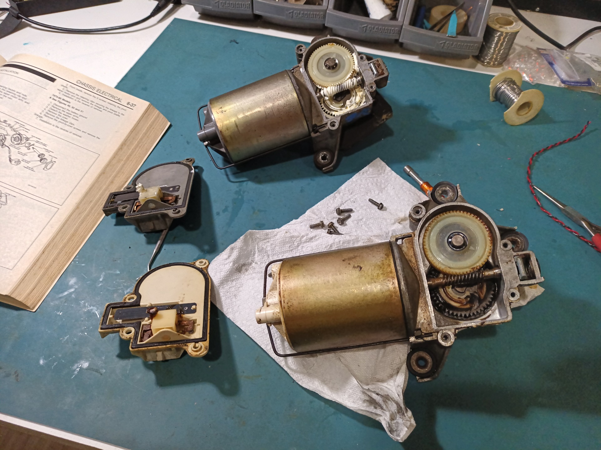
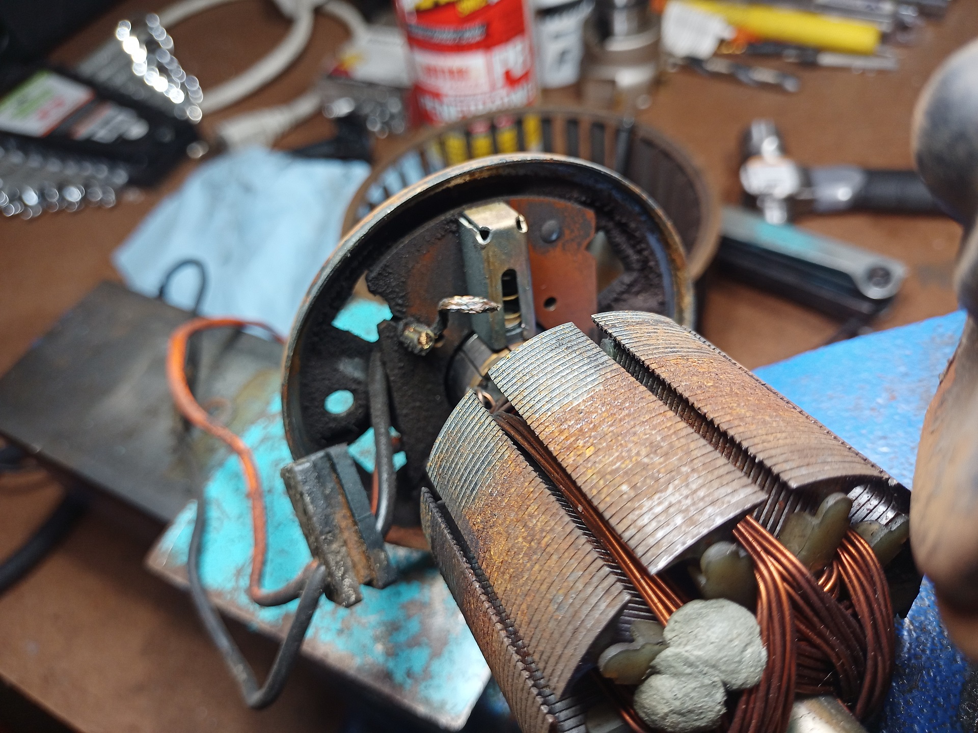
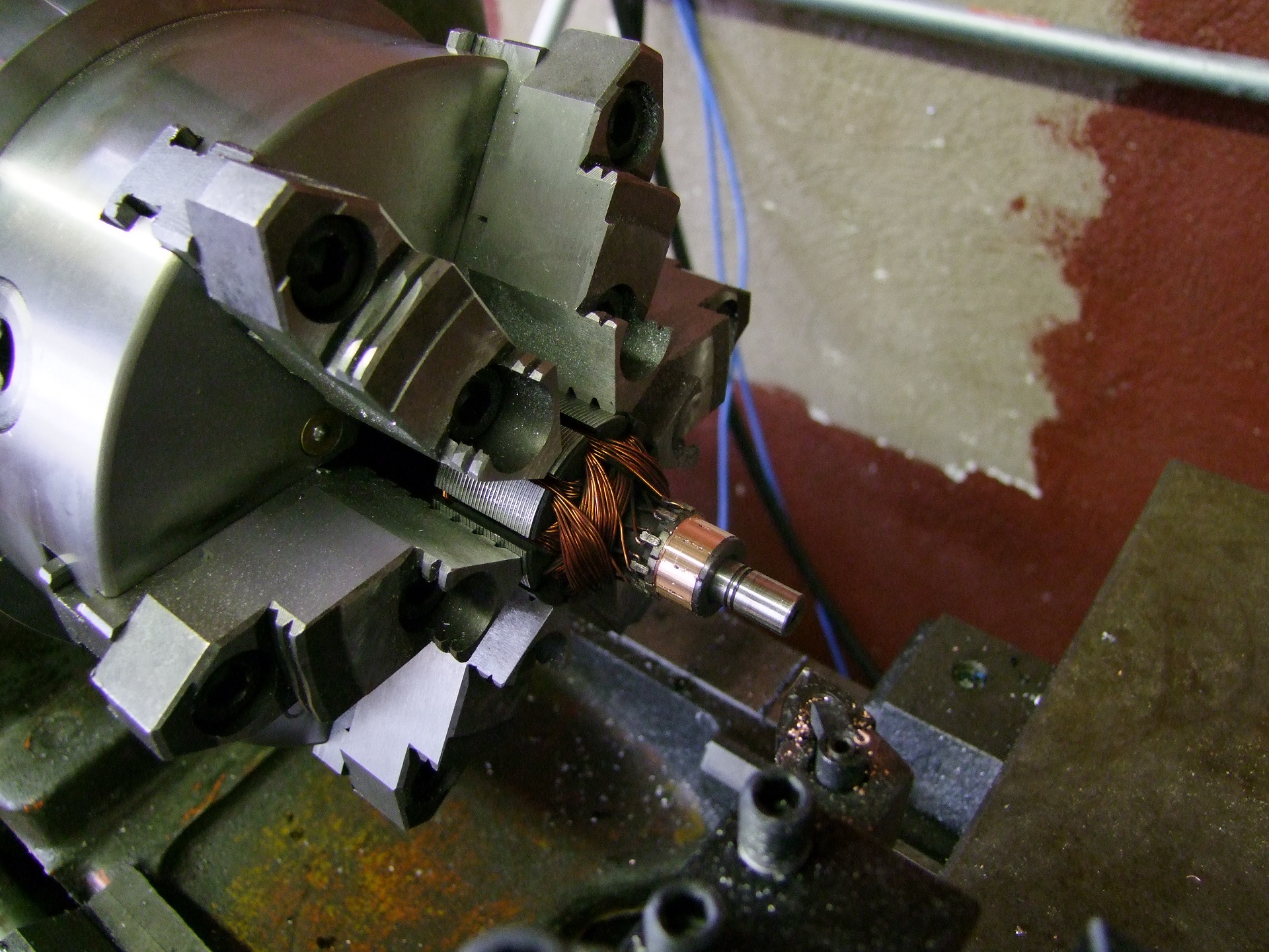
I took apart the junkyard motor for a quick visual once-over and to clean up and re-lubricate all of the gears and bushings (compare it at the top with Spool Bus’s motor with its totally dried out and crusty gearbox).
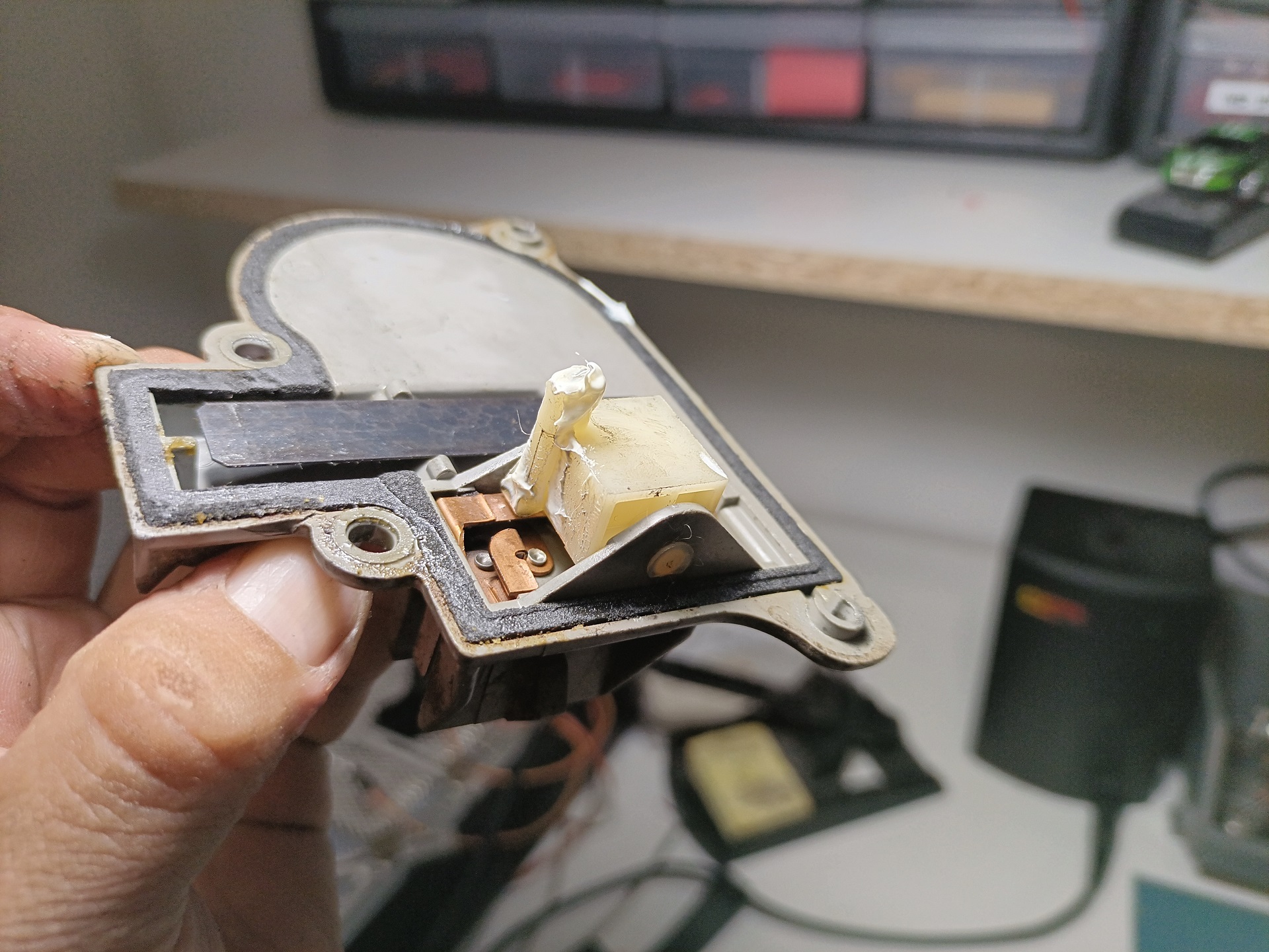
The parking switches on these things are just embedded variants of a self-stopping limit switch circuit, something I would do with a discrete snap-action or button switch or something.
The motor is able to receive 12V power through the normally-closed contact (shown in this position) via the springy copper strip until the little plastic finger pushing on it falls into a specifically placed divot on the drive gear. Once it’s in the divot, the strip gets pushed onto the normally-open contact (below the finger, with two little rivets).
At this point, the motor stops moving until the intermittent wiper controller clicks its relay, and that supplies a momentary pulse of power through this N/O contact, just long enough to get the motor moving and getting the finger out of the divot – at which point the motor runs as normal until it comes back around.
It’s definitely a very analog and old school way of doing limited-range motion without a modern encoder-equipped motor and its control module. Stuff like this still has a lot of appeal to me, because while it’s not very in-field configurable and changeable, it…. just works.
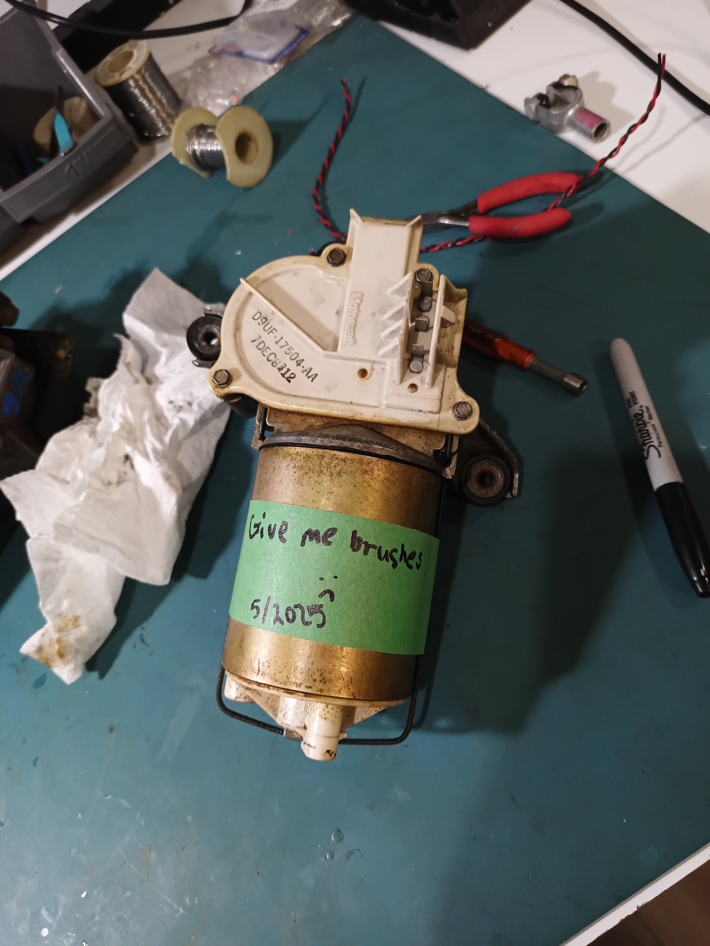
As with the blower, this motor has totally exhausted its brushes and only works if I smack it a few times, enough for the remaining stump to make contact (which is why I had to selectively hit potholes and curbs to get the wipers to cycle). So some time later I’ll pop it open and do that service and rebuild, including perhaps machining the commutator.
After SIGNIFICANT WIGGLING, I got the mounting screws lined up and piloted. These old rubber bushings are not very friendly when it comes to lining things up, and to make it worse, they’re in incomplete sockets (C shape, not a fully surrounding hole) so they like to fall out as I am trying to hold the motor with one pinky finger.
And the rest was simple. Now, when I said this self-parking motor circuit was “simple and just works”, I meant “Wow this motor just is doing whatever the hell it wants”. Some times, it takes 2 or 3 tries by the intermittent wiper controller for it to finally start doing the go-around thing. Other times, it parks and stops at this awkwardly high position. But after who knows how long, I could actually see in the rain again!
(As of September, this issue has largely resolved, and I think it was because the wiper motor contacts were probably old and not making good connections)
We’re not done yet, though. Not long after this round of work, one of the funniest van failure modes I’d ever experienced ended up requiring some Operation IDIocracy inspired shenanigans to recover from…


