Two-day update! Building over the past week must have completely worn me out, because last night/this morning/today I managed to sleep for 14 hours straight. In fact, I flopped down and fell asleep right before starting on the last update. So here is a combined two-day update.
It’s coming together. In fact, after I get some intimate time with the waterjet cutter, I pretty much have to just drop in the parts (and file, tweak, hammer, etc….) and wire up. Everything’s still a jumble of parts, but there should be a fair margin of time before Moto left for practice driving and tuning.
 Just a random thought.
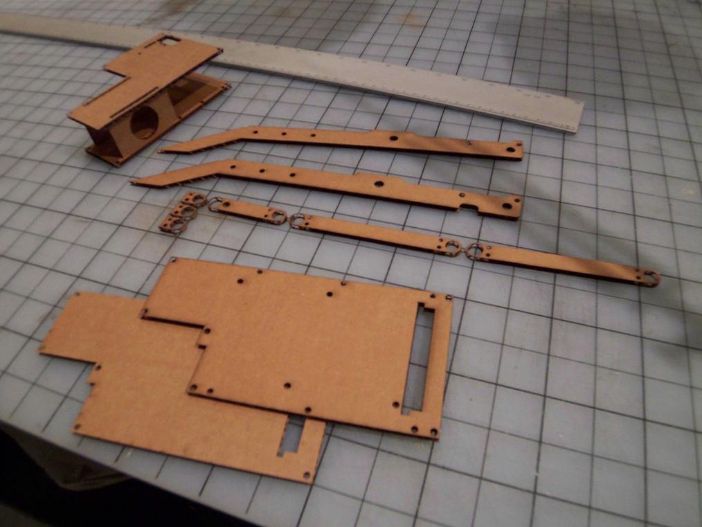
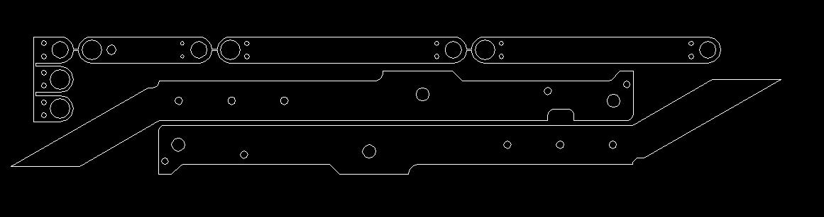 If you ever wanted to totally rip me off, here’s your chance. This is the 2D flat pattern for SP1’s arm parts that will be handed to an abrasive waterjet some time soon, and hopefully by the end I’ll have little bits and pieces of sculpted aluminum. Note that the arm links and linklets are connected by breakout tabs. Parts that small stand a chance of falling into the waterjet tank, where they will be lost forever until the next cleaning, so connecting them with thin tabs to other parts or the main sheet of material prevents this.
I wonder how many would-be parts they mine out of the tank every time they clean it out.
 Oh, hey, let’s make a cardboard robot.
I got some time on the Media Lab’s GIANT LAZER and made some prototype / sanity check parts out of cardboard. Not too exciting, but I’ve seen people cut things as odd as graham crackers and chocolate bars on it also (the ML smelled dessertful that day). Especially important is the EBay pieces, since it lets me know that everything does indeed fit IRL.
Here’s a video of it in action (Metube)
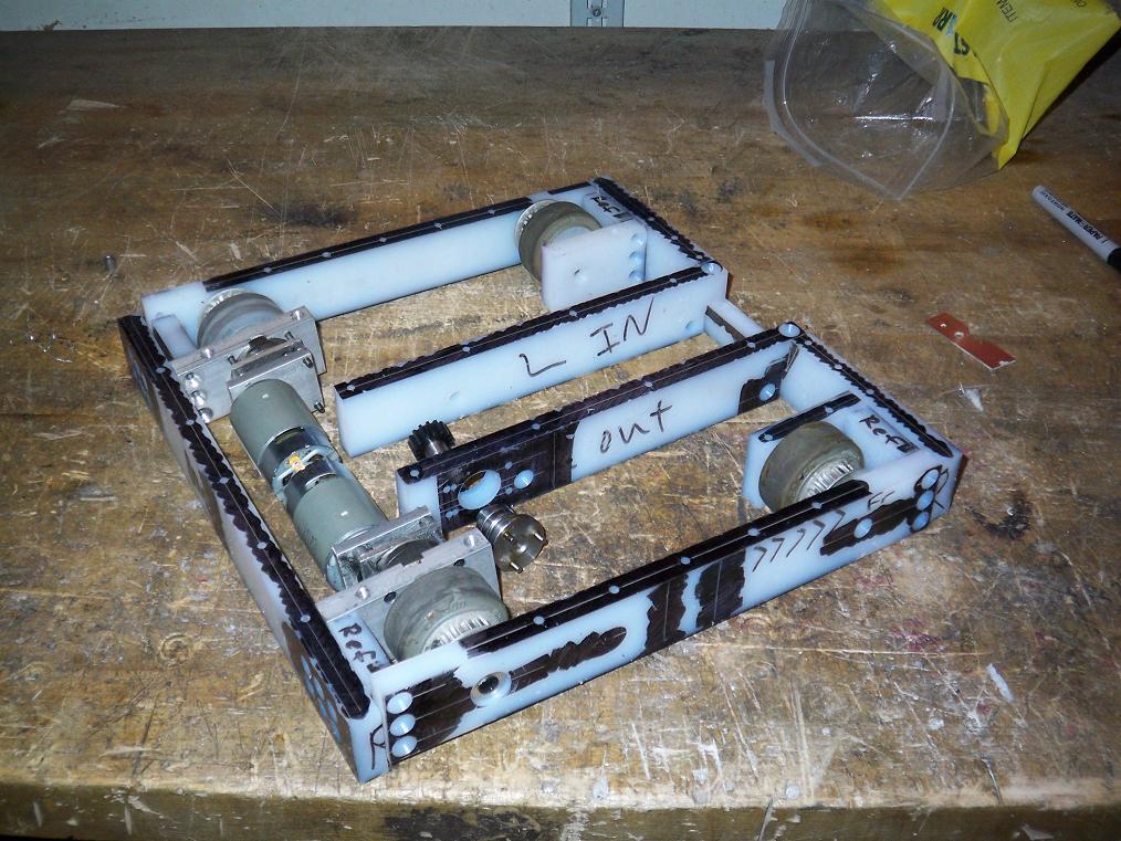
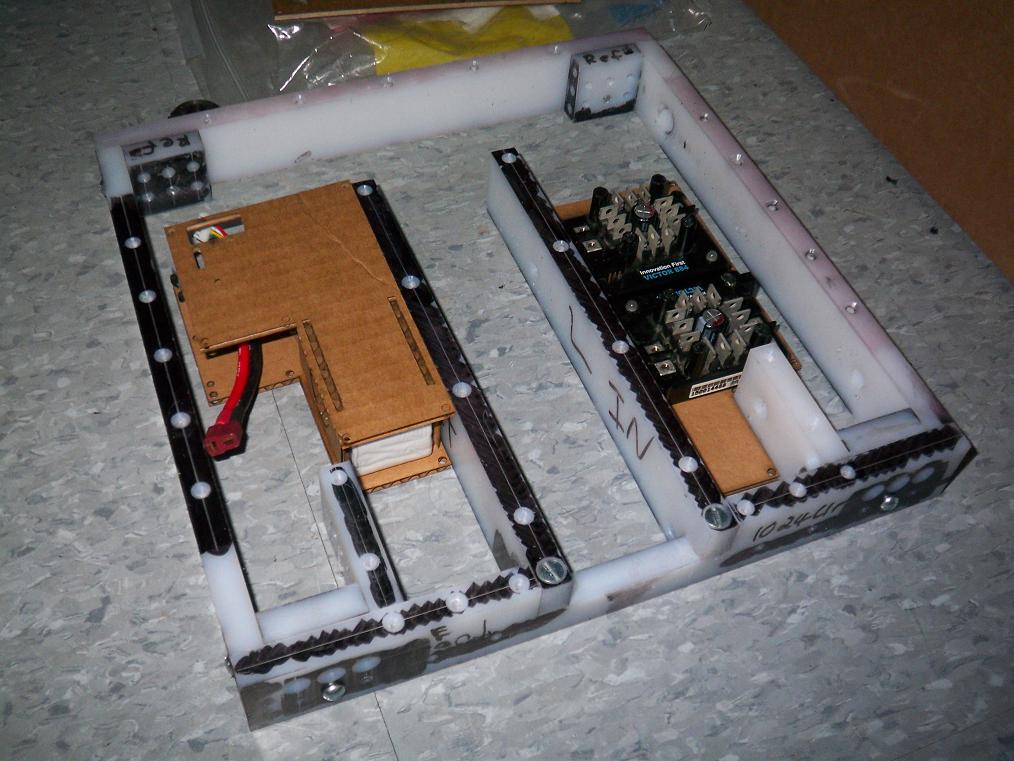 Putting the test assembly through a somewhat-assembled frame.
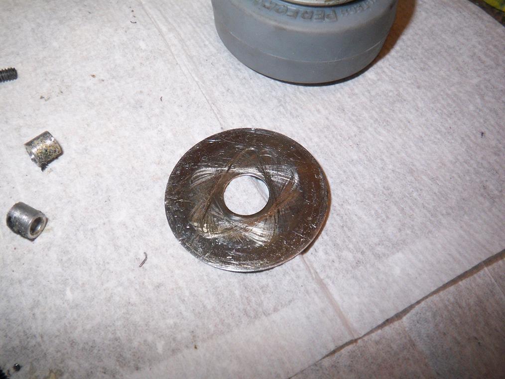
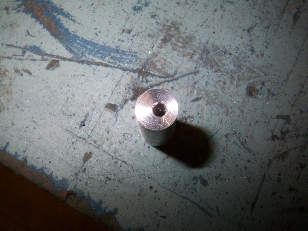 Another precision product of the MITERS lathe, the inter-arm-beam-standoffs! I have no clue what on earth happened here. The drill bit sure looked like it went in straight and didn’t wobble on start. I suppose not.
Just to be extra-careful on the remakes, I didn’t drill the whole length of the part since it was going to be a standoff anyway. I also tried using a center drill to start the hole. Go figure, there was no center drill available, so I made do with a countersink. That somehow worked well.
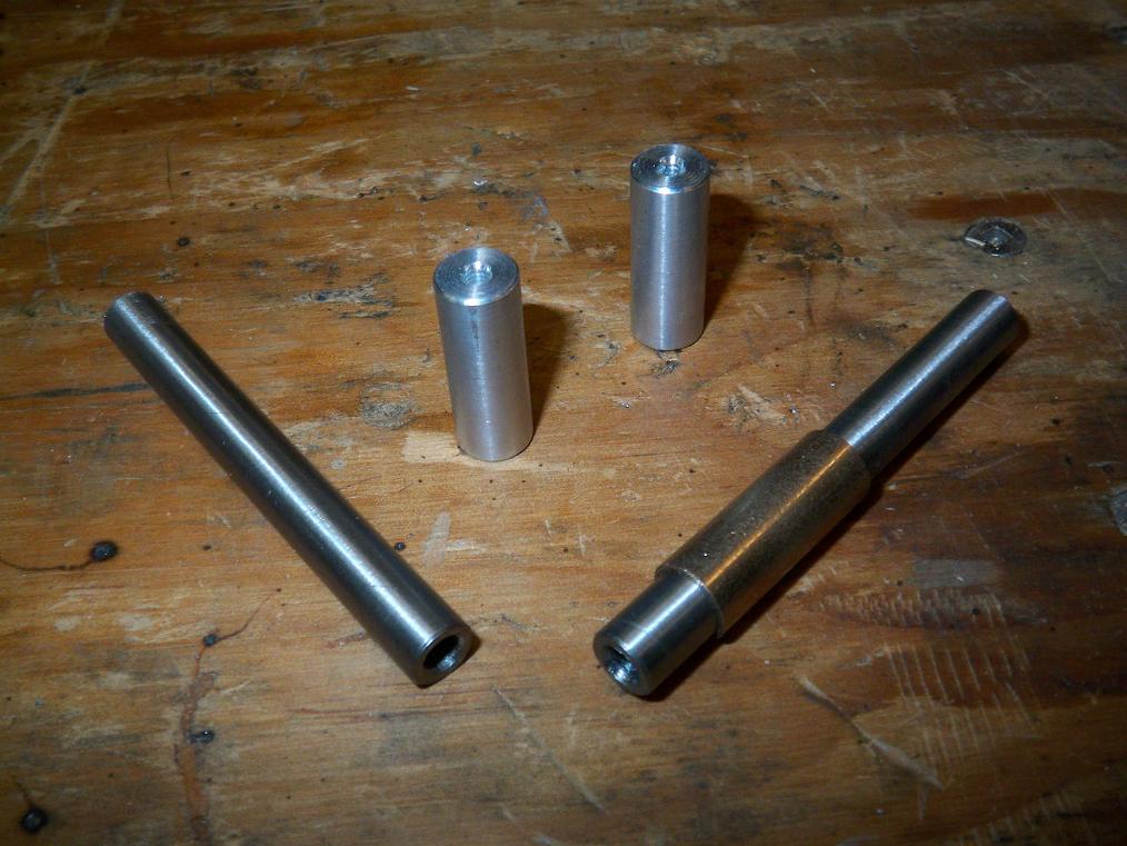 Here are the arm standoffs along with new hinge pins. Only after I disassemble the arm did I discover that in fact BOTH bottom hinge pins were bent, not just the front as I thought. A good punt directly to the arm from a drumbot will do that, I suppose. I might try casehardening the pins using the oil-dunk method, but suspect they might warp. If the MITERS lathe could machine the steel using chipped and dulled tooling, it probably isn’t very hard.
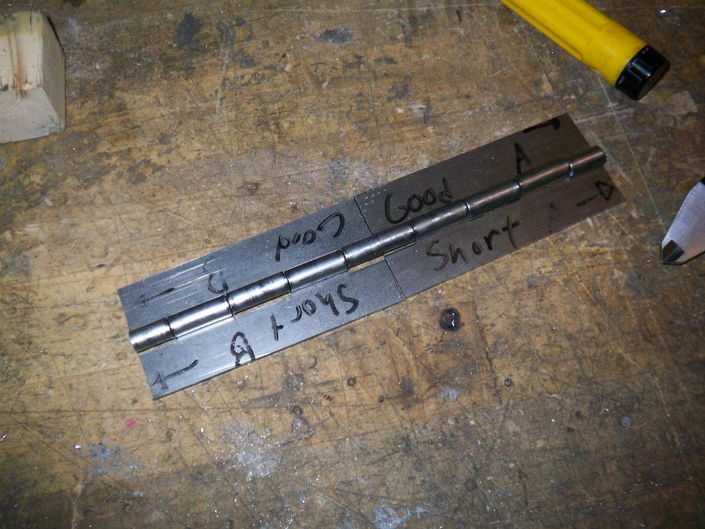 Hinges cut out and milled to (somewhat) the right size. I was off by one digit in the McMaster part number and got a hinge that’s slightly wider than what I need. Not wide enough to warrant a return , but wide enough to interfere with the design.
So the solution was to mill them down to size. In another episode of Charles fucking hates flakey public tools, the ML mill has a severe issue with Z-axis drift and backlash. I swear I cranked the dial to exactly what I needed every time, but the worst inaccuracy is still .05” short of what I actually needed. Fortunately this .05 does not interfere with the design, and I didn’t feel like bandsawing off another section of hinge by that point. Half of each hinge is at the correct dimensions +/- .002, and so it’s acceptable. I wonder why those parts were consistent.
Maybe if I had checked my progress as I lowered the Z-axis for another pass I would have saved alot of headache as I would have known that I was about to fly way past the stated dimension. Oh well.
I was tired at that point and decided to save the drilling for another day.
 …but neither tired enough nor pissed enough at the mill. Finding a 1.5″ square rod of 2024 aluminum just gives one more botting energy anyways. That’s exactly what happened – while walking out of the lab, I discovered the 3 foot chunk of Al in the material rack and immediately decided to extend my hours.
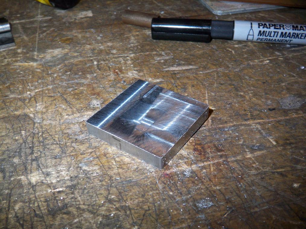
Here’s the arm gearbox mount milled to spec. The 1.5″ thick bar took almost 15 minutes to cut on the horizontal bandsaw, mostly because it’s also old and creaky and I had to set it to go REALLY slow or the blade would jump the pulleys, resulting in bad.
For these cuts, I set the Z-axis lock a bit such that I could feel the backlash in the handwheel before it moved the axis. This was a godsend.
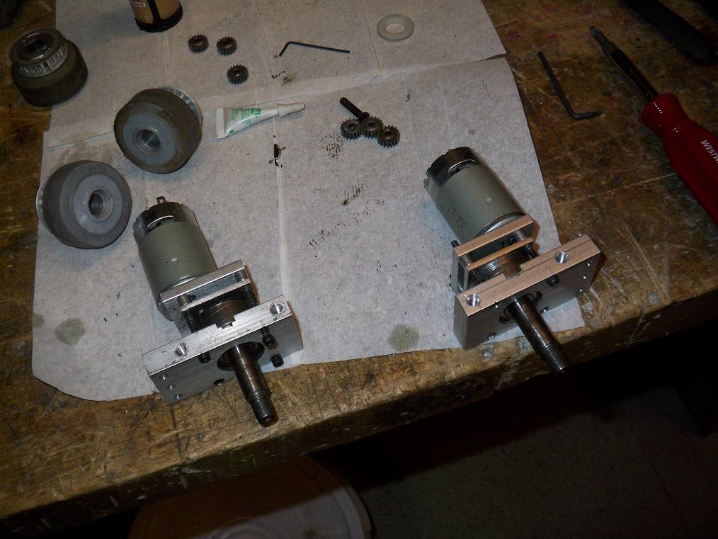
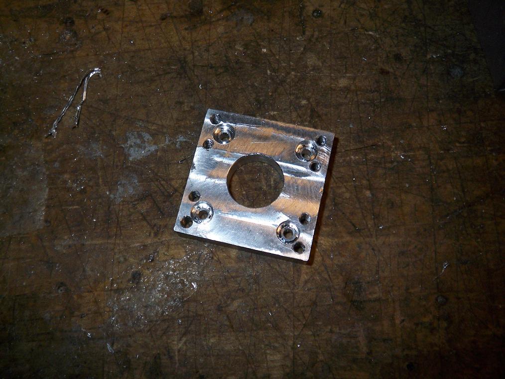 Drilled, threaded, and countersunk where appropriate. The finished arm gearbox mounting plate, made of a chunk of 2024. I wonder what else on the bot is 1.5″ square, becuase I want 2024 mounts across the board now.
The 5/8″ hole was made using my ghettoedging method, even while the edge finder was staring me down in the endmill rack. It worked well. An added twist this time was to run the spindle backwards such that the tool contacts but doesn’t cut.
Oh, hey, maybe I can remake that dumbass drive gearbox middle plate.
 Front end of arm gearbox assembled. With retaining ring and everything. There are a total of THREE bearings that will be supporting the extend-o-shaft this time. That means it will probably bend and ruin my day anyway.
So that concludes the work as of tonight. I might try to fit the chassis together soon and maybe wire up for the odd test drive or two.
Oh, and I also found a 1/8″ plate of 2024 in the scrap bin on my way out after milling the motor mount. Fortunately, I could think of no parts that involved 1/8″ plate, and so did not stay a second time…
Maybe tomorrow.