I will never take apart TB’s gearboxes again.
I will never take apart TB’s gearboxes again.
I will never take apart TB’s gearboxes again.
I will never take apart TB’s gearboxes again.
Did I mention that I will never take apart TB’s gearboxes again?
Today was a combined 8 hour work session, three of which were spent trying to put the gearboxes back together.
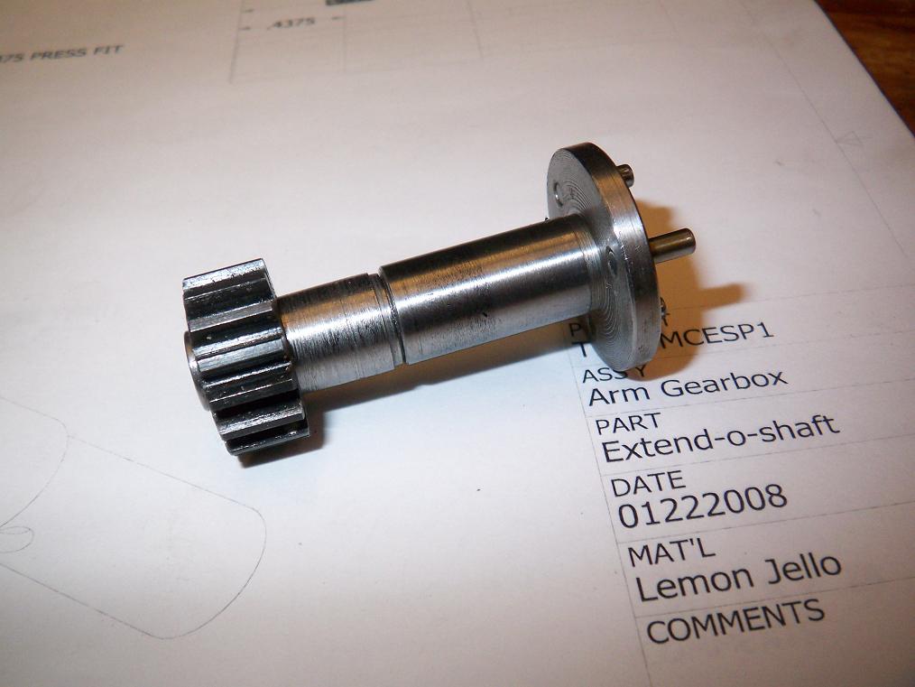
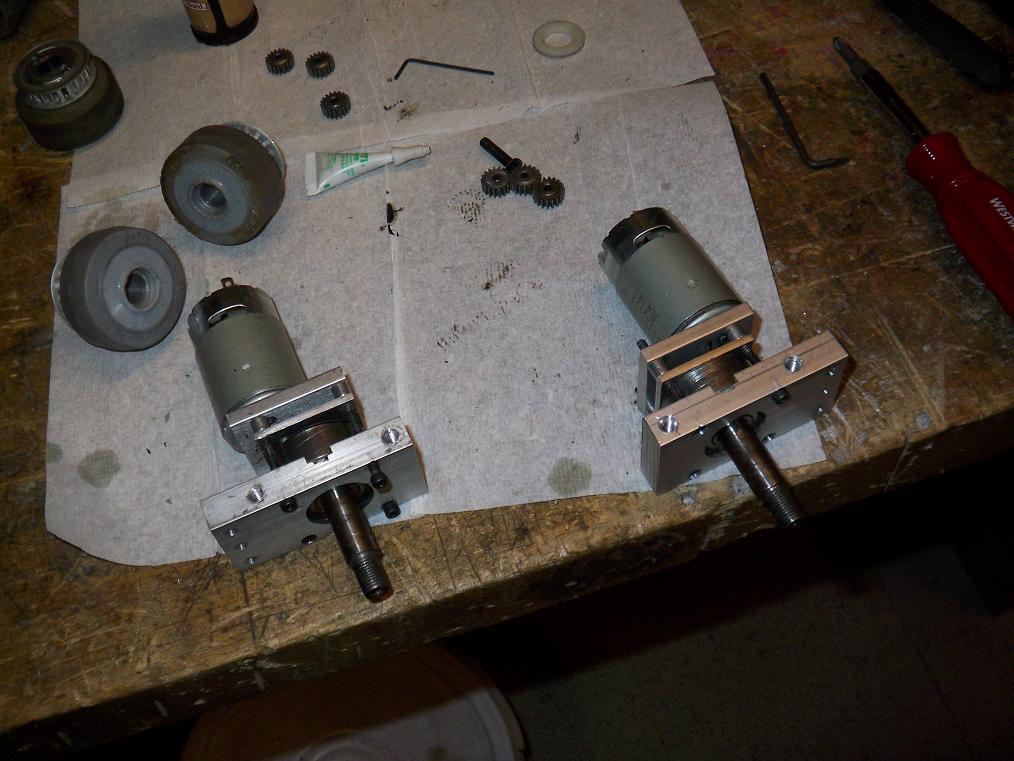 I took the GBs apart to swap out the almost 4 year old motors. I got these at Dragon*Con 2004, and they have seen service in 2 builds of TB and also Trial Bot 1.0’s weapon assembly. The brushes are shot to hell and the armatures are half toast. In the same session, I also bored out and installed a new 2″ Colson wheel to replace one of the rear drive wheels, which has a large chunk missing. The rest of the wheels are still smooth and round, so I did not replace them.
The new motors are real Johnson power tool motors (Serious Businessâ„¢) and are rated at 12 volts. Since the bot’s running 15v this time, I decided the old 7.2v motors were probably going to go poof with a minute’s driving while hurling the bot along at Warp 2√π.
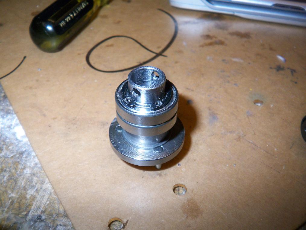
So the problem was putting the gearboxen back together such that they still worked. These gearboxes have three main parts – the motor mount plate, the intermediate stage bearing plate, and the outer bearing/mounting plate. Only one was made by a repeatable process – the outer plate, which was CNC’d. The rest have slight variations in hole placement and dimensions.
Suddenly, holding a jumbled pile of gearbox parts, I forgot which part went to which gearbox.
In two combinations of three items with one held constant in each, there are four possible arrangements of parts. To add even more complication, though, the middle plate is square and symmetric (supposedly) with four possible orientations. Had the parts been milled or made with more exacting specifications, this won’t matter. But unfortunately there is only one or two positions of the middle plate in which any combination of the above parts would work (otherwise the gears run into eachother and bind). So I was now dealing with up to 16 ways to put the gearboxes back together.
Great. Whatever. In the end, one works fine and the other still binds some. The interference appears to be from the first stage, and rather minor, so I’m tempted to just let it wear itself in.
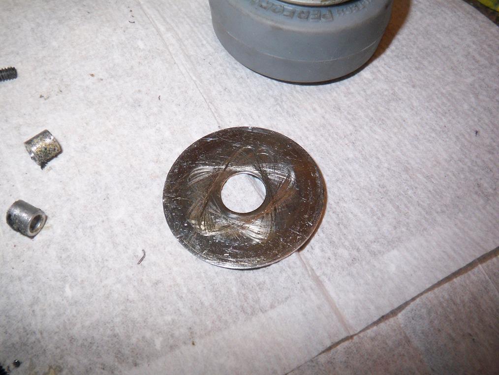 Odd wear pattern from when I took apart the left drive motor. The HF motors have 3 planet gears. This is a 5-pointed wear pattern. 5 is not a multiple of 3. Can someone tell me what crazy harmonics are at work here? Is Satan in possession of the bot? Good.
 Milling around. This is the center “cutout” where the arm sits. I couldn’t find an edge finder, so I did it up the ghetto way – coat the end of the piece in permanent marker, then crank the axes until the edge of the cutter just barely scrapes the coating off without actually cutting into the piece. Conveniently enough, your cutter is already in the spindle, and you can zero the dial / DRO and go. I got amazingly close by this method and handwheel dial reading alone – 3.247 on a 3.25″ long cutout. That’s better than the UHMW’s manufacturing tolerance, so I’m happy.
I plan to use this ghetto-edging tactic more often. Sure beats digging out an edge finder, making sure it runs dead concentric, then accounting for the tool width offset, then taking it out and putting in a cutting tool…. maybe on a machine without a mile of backlash.
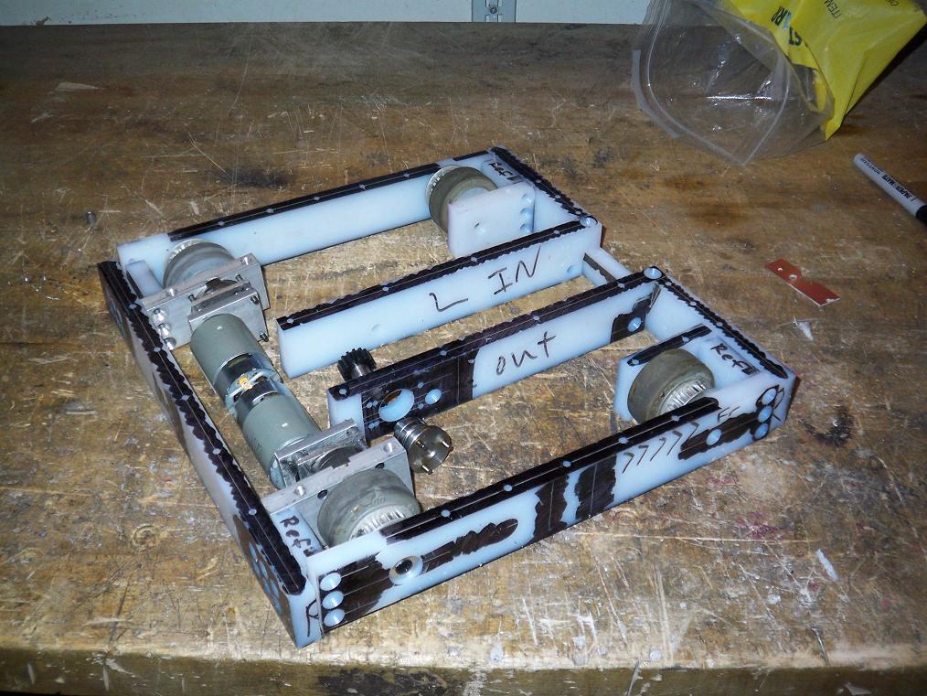 The bot as of now. It’s looking like something. Holy snorf.
On the way is a 30 pound package containing one (1) 12″ x 39″ x 1/4″ 2024-T3 aluminum plate and one (1) 12″ x 28″ x 1/2″ 2024-T3 aluminum plate with one side mirror finish (ooh, shiny). That’s enough aluminum to last me a long time. I got all of this for a bit under $100, or about $2.8 per pound of good aluminum. That’s a killer deal, and some of that UHMW might be replaced by some heavy metal soon.
It’s coming together! Bot onwards!