After a marathon 12 hour work session, SP1 is now approaching the “looks like something… kinda” stage in construction. The frame holes are now mostly drilled. The spindle for the arm gear is also complete. Some big aluminum plates are now on their way (the front desk is going to hate me in a few days) and flat patterns have been made for the waterjet and GIANT LAZER.
I still haven’t figured out how I’m going to get to the event. Go figure.

But before we begin with the usual monotonous build pics, here’s a picture of a lathe headstock bearing.
After one of my “.375 inch” drilled holes came out .393 on one end and .420 on the other, it was obvious something else was up. If you’re keeping track, that’s a 1.3 degree taper across a hole about 1.125″ long.
The MITERS lathe has a severe case of tailstock misalignment. I turned two pointy centers, put them end to end, and discovered that it was off both vertically and horizontally by about 1/16″. That’s insane. Naturally, I must think of ways to remedy this that involve random hacks and waste my time.
- Crank the tailstock adjustment screws, the first obvious choice. They haven’t moved in 40… 50 years? Since 1500B.C.? It took Herculean effort, but I was able to eliminate the sideways misalignment.
- Read the instructions on how to lower the spindle by dropping shims from the headstock bearing
- Attempt to, but pop out a bearing spacer (The bronze component hanging awkwardly from one end)
- Try to pop it back in. It flies out and lands somewhere in the inner cavity.
- Take half of headstock apart and dig around interior of machine. Fumble through mountain of chips, drillings, and curls.
- Find it, jam it back in, and pretend that never happened
- Fold pieces of copper foil to the correct height and wedge under tailstock ways. Works momentarily before foil compresses and alignment is off again
- Jam bigger piece of foil under tailstock ways. I’m stopping, I don’t care any more.
And that’s how I blew two hours and ended up covered in 60+ year old machine grease. That must be really good for me.
Anyways, buildpics.
 When you have no cutoff tool and need to get stock of a relatively small diameter cut to a certain length, what do you do? One way is to hacksaw it, but I couldn’t get the hacksaw to stick to one spot on a threaded bolt (the only source of 1/2″ non-hardened steel I had). The “hack” was to take a biiiig drill bit and just drill the thing down. This cut was consuming WD-40 and turning it into thick white smoke as fast as I could spray it on. In the end, it worked.
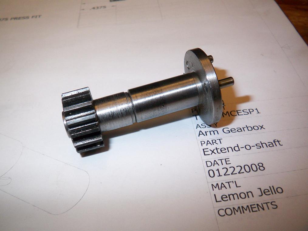
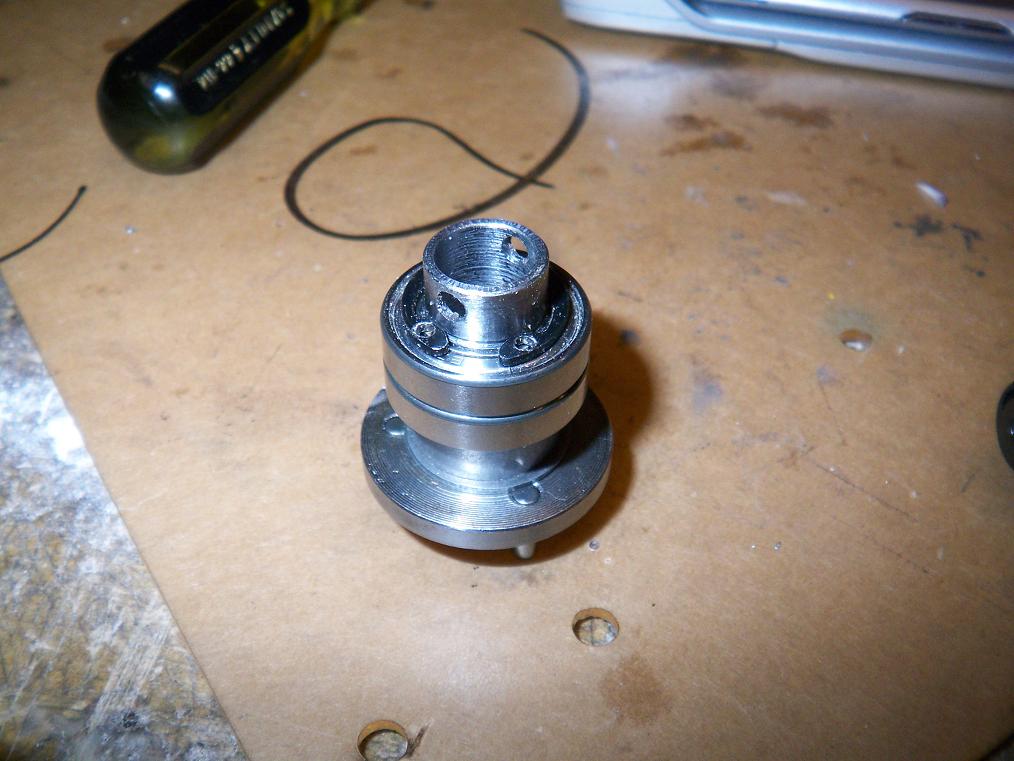
 The finished product of the machining session – A hollowed out drill spindle and the EXTEND-O-SHAFT 2000â„¢. I moved the arm drive gear farther out to the middle of the bot this time around, and so the normal drill spindle as-extracted from a drill won’t reach.
By the way, I turned a 6″ long 1/2″ diameter steel bolt into that stupid 1.5″ rod the gear is mounted to. A bit of a waste, but hey.
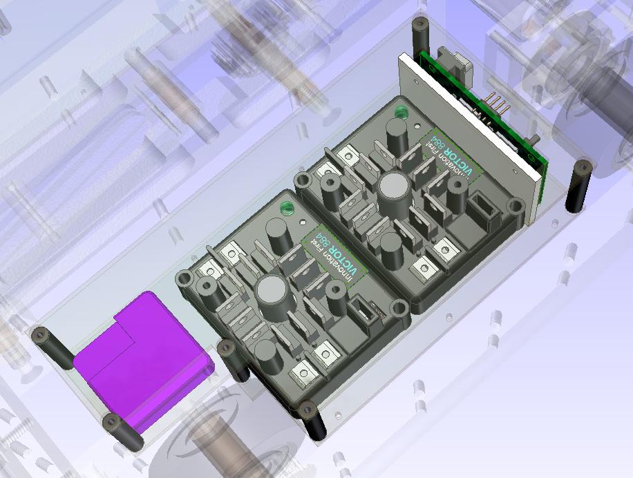
 The assembly.
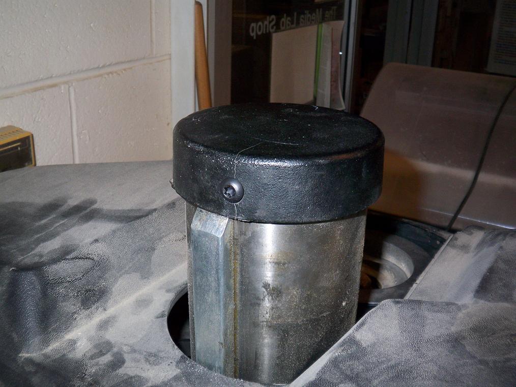 In another episode of “Charles rigs random hacks to fix mildly abused public tooling”, here’s a quick rigged fix to the top end of the Media Lab mill. The mill head can be adjusted by a crank which drives a rack and pinion. The problem is that the head liked to get stuck in an elevated position and the black metal cap, which normally stop the rack and lets it exert leverage to get the head back down, broke off. And thus the mill can only get higher.
Someone had tried to drill a hole and using a set screw-like setup to hold the cap down, but it appears to have failed and cracked the cap. The solution was to drill through the big cast iron column and drive the screw through it. Now the rack butts against a 5/16″ cap screw, which allows the head to move back down again.
I didn’t even get to the milling part this time. Oh well.
 I hate retaining rings. Absolutely hate them. They’re a pain in the ass, need a special and not-common tool to work, and like to fly off into random directions and get lost if you don’t work said tool with utmost precision. I would never, ever use retaining rings on anything I build.
But Charles, isn’t that a retaining ring on the drill shaft? Yes, it is. I used a retaining ring to hold in the bearings on the Extend-O-Shaftâ„¢ and drill spindle. In the end, it’s still the most compact way to keep something axially aligned on a shaft. This was yanked from the pile of drill parts I always keep around.
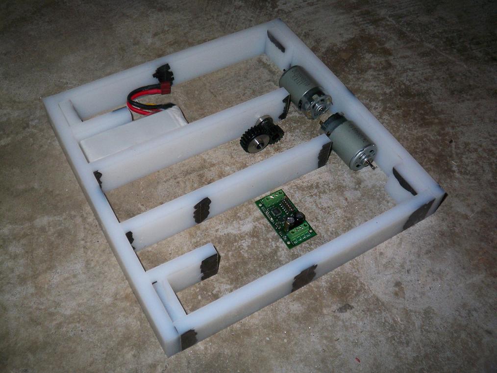
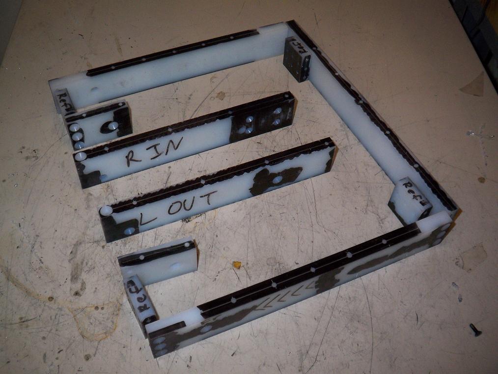 Frame holes mostly drilled. This whole process tool about half an hour, since I had already center punched the holes. UHMW is very soft and forgiving, so the drill process was as simple as setting the depth stop on the drill press and slamming it down on each center after a very quick pause so the bit can align itself with the center punch dimple.
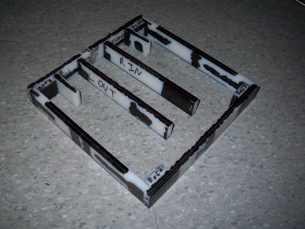
The dead axle pin holes were made flush on the bottom with endmills in the drill press spindle. Countersinking was also smooth and painless because of the depth stop.
There’s one fuckup on the front left side where I let a piece escape and it got sucked into the 3/8″ drill bit I was using to start that axle hole. So now there’s a 3/8″ through-hole where there isn’t supposed to be. Fortunately, this part is identical to the one I made for MCE. I might just swap it out.
Okay, so now that the tools are less dysfunctional, I should be able to build quicker. Stay tuned for more updates, and bot on.