I’m still waiting to jack someone’s Media Lab login. In the mean time, I’m wrapping up some loose ends. After all the waterjet-cut parts are done, the bot is only a few hours away from testing and tuning.
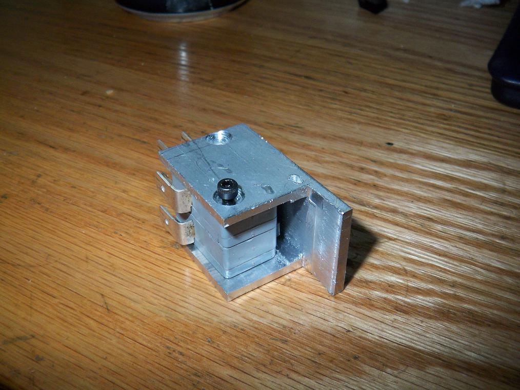
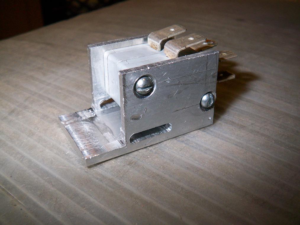 Finished master power switch assembly. The bot is off when a key of appropriate dimensions (read: stick of steel) is inserted into the slot, tripping the two normally-closed switched to be open circuit. The key is a good indicator that the bot is inactive. Additionally, the bot cannot be randomly shut off in battle by the switch, unlike removable links or normally open switches.
If TB does stop moving in a match, something else has gone horribly wrong. If it suddenly stops with no contact from the opponent, I’m probably half a second away from running through the arena walls with a fire extinguisher.
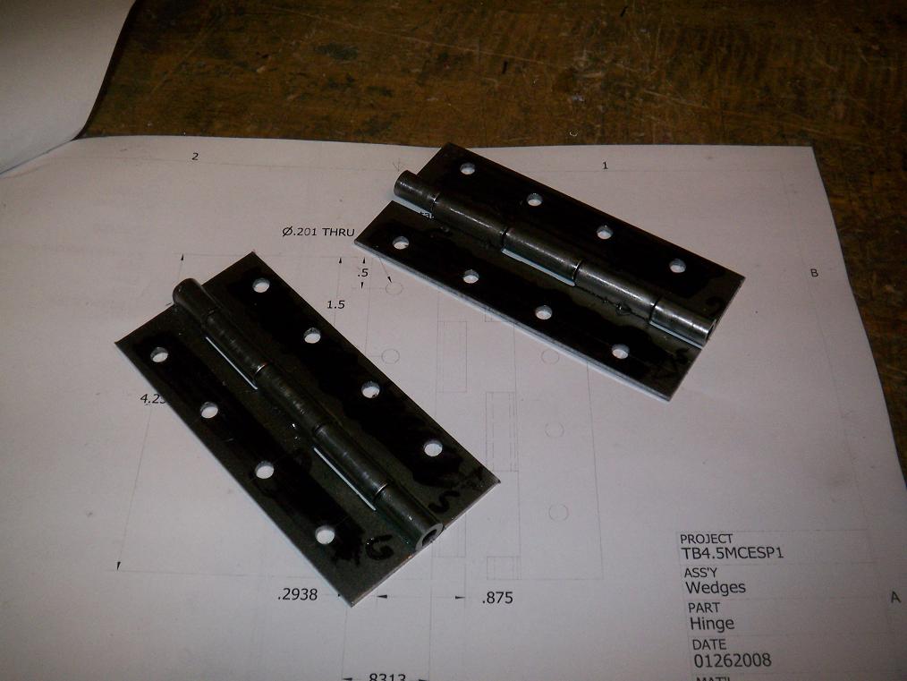
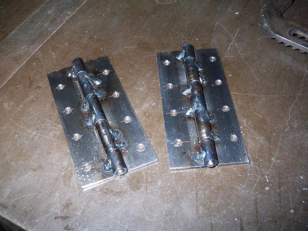 At the same MITERSing session, one of the guys there tack-welded the hinge seams. I decided against making this my first ever welding project since it was a relatively precise part that would take a while to redo if it got blown up.
In the end, the hinges are still going to be attached to soft, squishy plastic. The tack welds at least prevent the seam from unrolling. Welding the whole seam would have been unnecessarily risky.
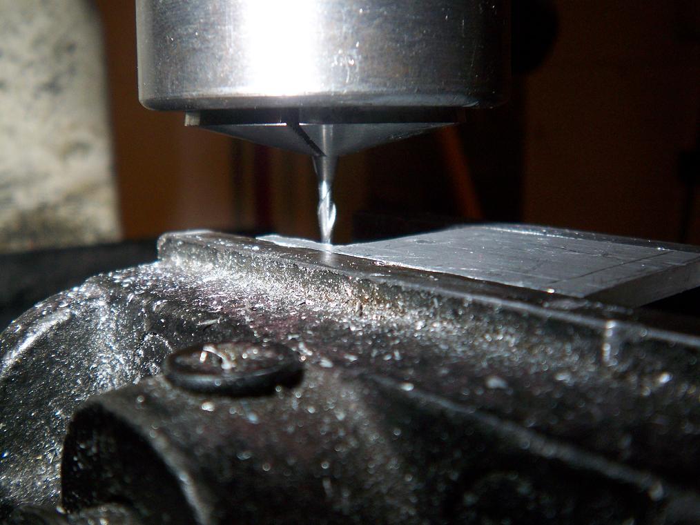
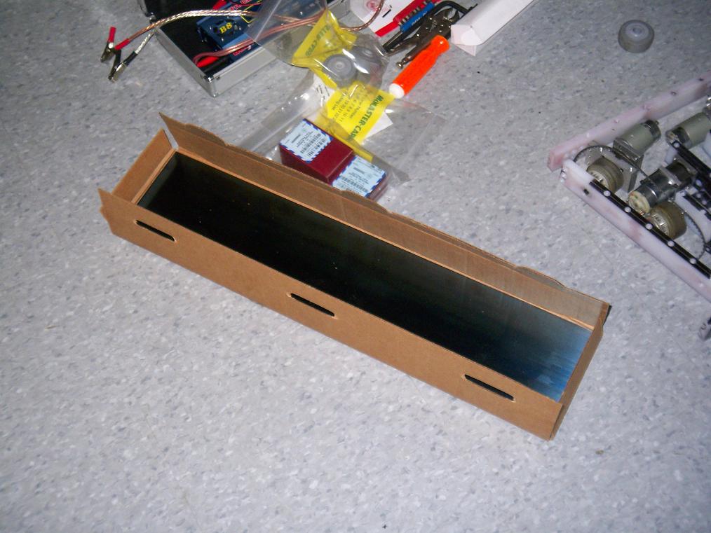 Hey, it’s a sheet of blue spring steel. I got this .025″ thick strip after deciding that TB needed some more perimeter defense. There will probably be bot-sized strips waterjet-cut out and attached to the UHMW. The advantage of having an über-hard material on the bot is the reduced likelihood of a KE weapon digging in and tossing the bot. UHMW flakes away nicely enough, but if it can save me from some damage, it’s worth a shot.
This hard coating should be even more advantageous on the front wedge, which is a very low angled surface. I might look into making some shapes for that.
 I also replaced all the wheels. Originally, it has just been one wheel, but that left the bot a bit uneven. So why not.
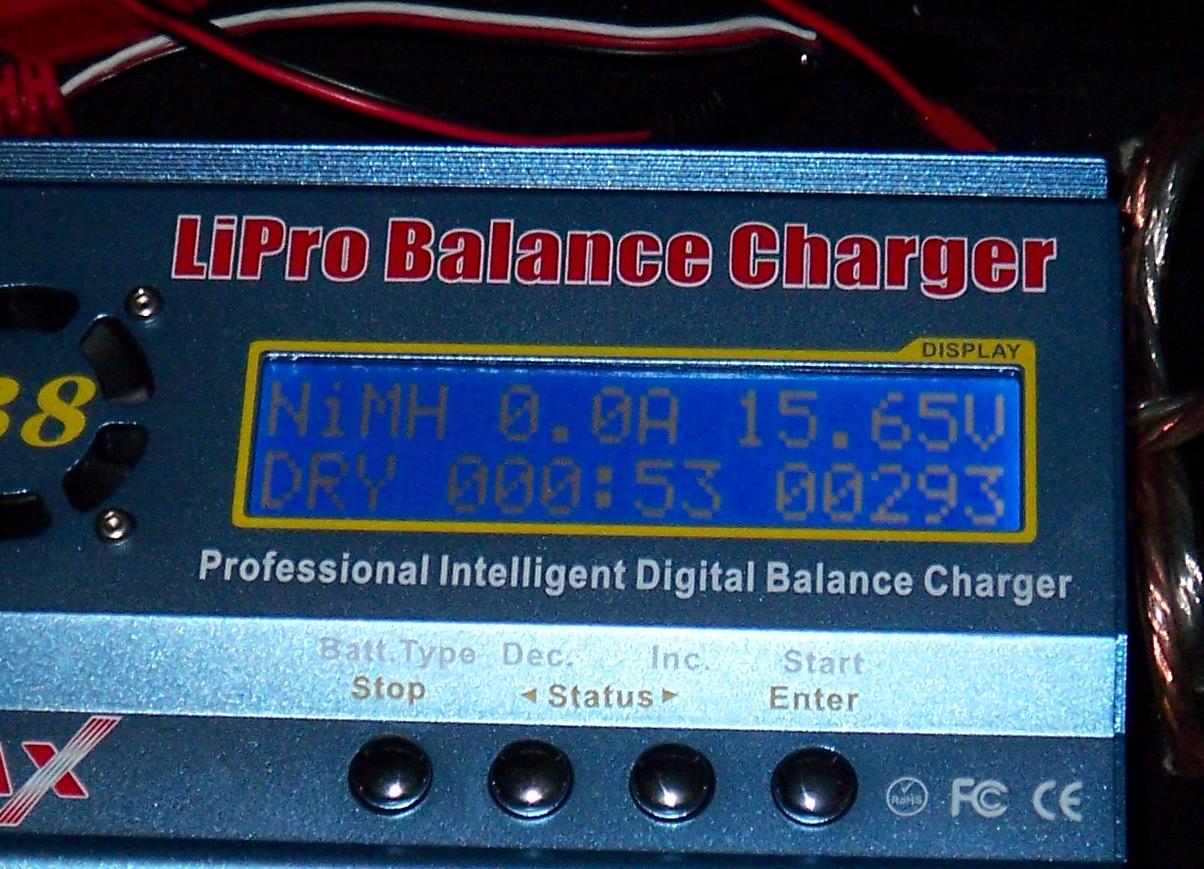 A function of the charger that I had never seen before. In between battery cycles, it allows you to set a delay before it moves on to the next step. In the programming section, this function is called “Waste Time“. Apparently, the physical manifestation of that is “Dry”. I assume it just got done washing.
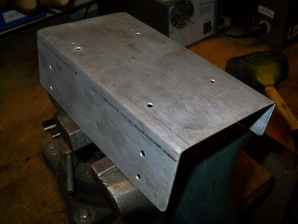
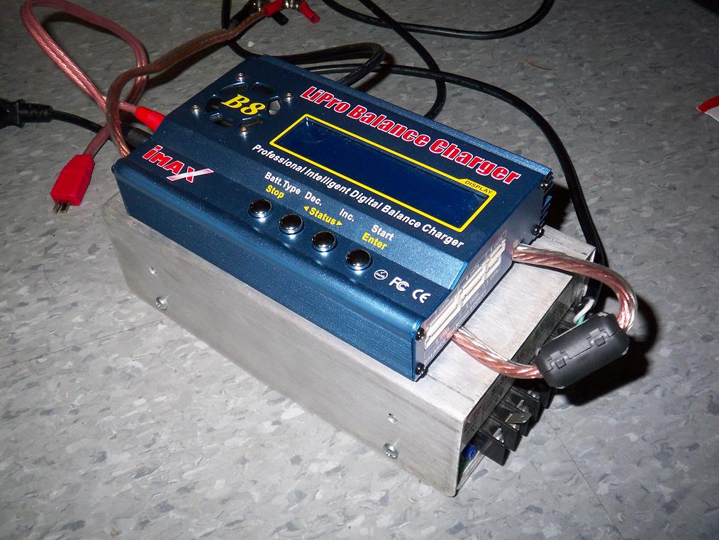
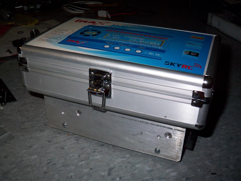 Speaking of the charger, here’s the finished “integrated charging package”, which is really just the power supply bolted to the underside of the carrying case. Hey, it gets the job done. All the charging accessories go inside the carrying case, and I left a long enough lead from the PSU that the charger can be moved outside the case if needed. The metal frame elevates the case off the power supply surface by about 1/2″ to allow its cooling fan to function.
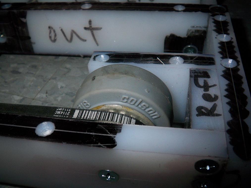
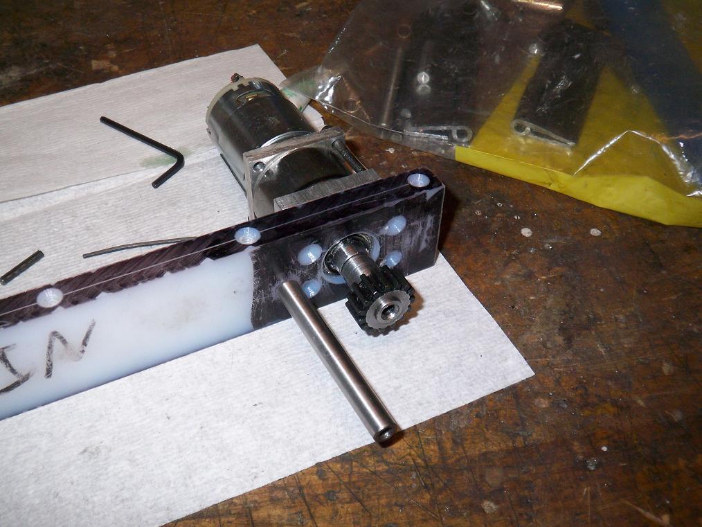
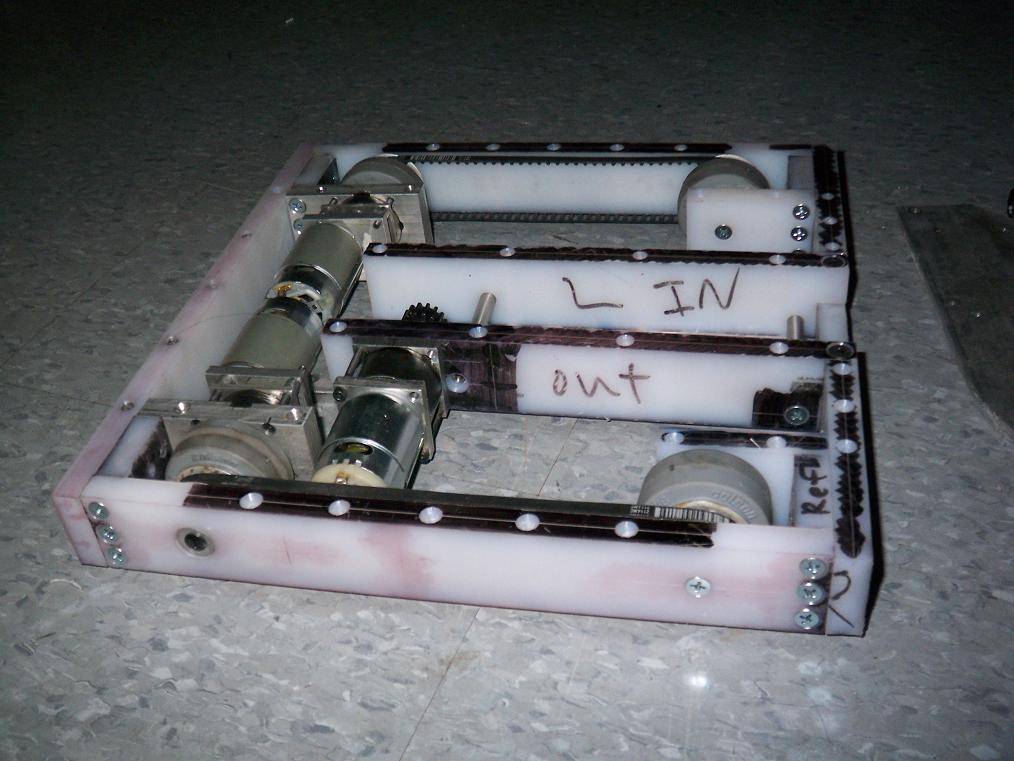 Test fitting all mechanical assemblies (minus arm) for the first time. There were some tight spots as usual, but a few minutes of running in and some drops of teflon-infused oil solved that. The drive wheel centers seem to be short by at most a hundredth of an inch, but it’s enough to get the belts a bit floppy. No slippage, but I might drop a roller tensioner or two on them anyway.
Oh, and the pink sharpie stains are fully visible on this side of the bot. The stuff seems to have embedded itself into the UHMW, and paint solvents only cleans most of it off. Instead of making the whole bot pink, I’ll just leave it in the Random Sharpie color scheme.
So, now that the only thing left is hauling a 40 pound slab of aluminum (when it arrives) to the Media Lab and hoping the waterjet is open, there’s not really much more to report. Class begins next week, and Motorama is in 2 weeks! AHHHHHHHHHH! I still haven’t figured out how to get there yet.
Anyways, boto[x].