Yes, another one! I wonder how many build report posts I can rack up before the bot’s finally done.
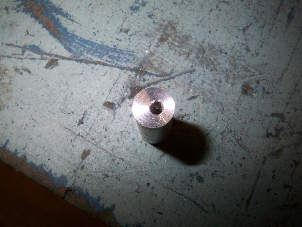
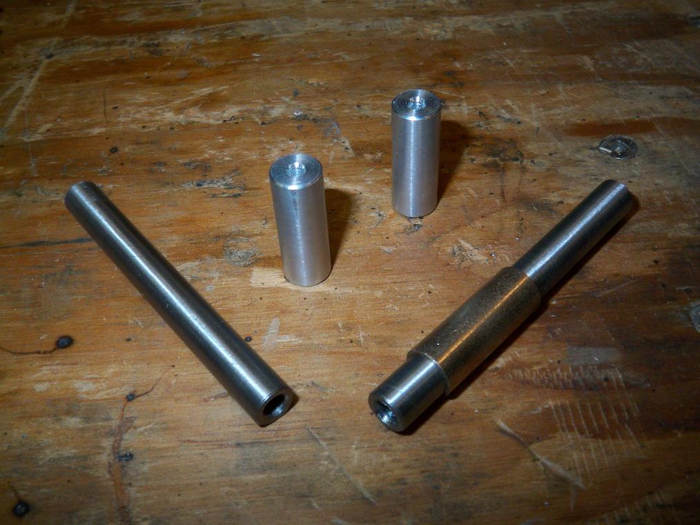
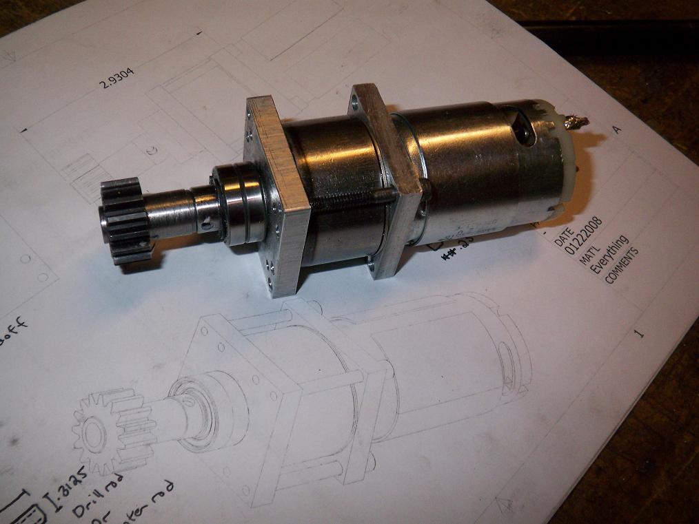 Completed arm motor assembly. This is a stock drill motor with the casing removed and with a modified output shaft. The motor is a 540 size – slightly shorter than normal drill motors. With the intermittent duty cycle of the arm, I decided a shorter, overvolted motor would perform just as well. I had to file down the endcap of the 550 drill motor in MCE’s arm gearbox such that it would clear the drive belts. With this, I won’t have to do it.
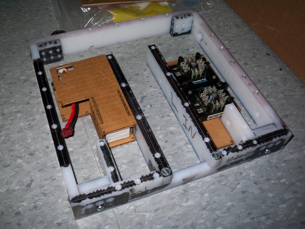
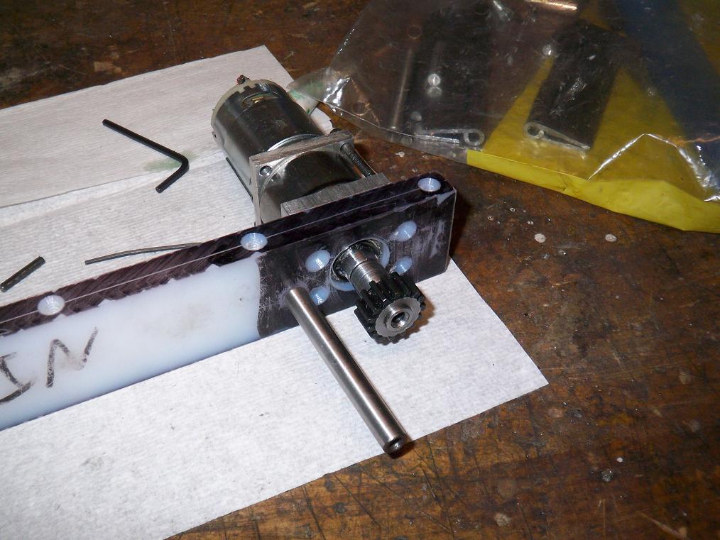 Test mounting shows that most everything is where it needs to be. Unfortunately, while deepening the right arm rail hinge pin hole to allow the final assembly to sit at proper width, the UHMW managed to flex out of the clamp and get sucked into the drill bit, causing one hole to be drilled 5/16″ all the way through. This doesn’t impact the arm operation, but does lose me a fastener location.
UHMW has a propensity to suck itself into whatever cutting tool you’re using at the time unless it’s REALLY well secured.
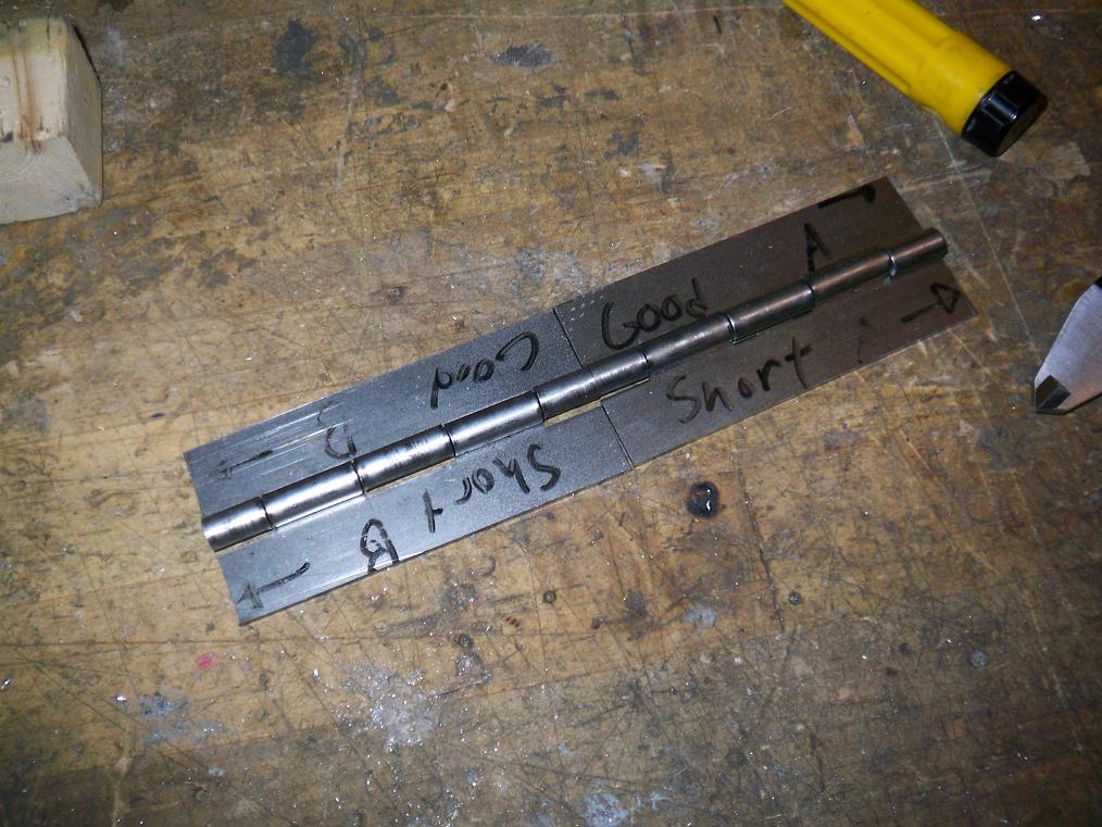
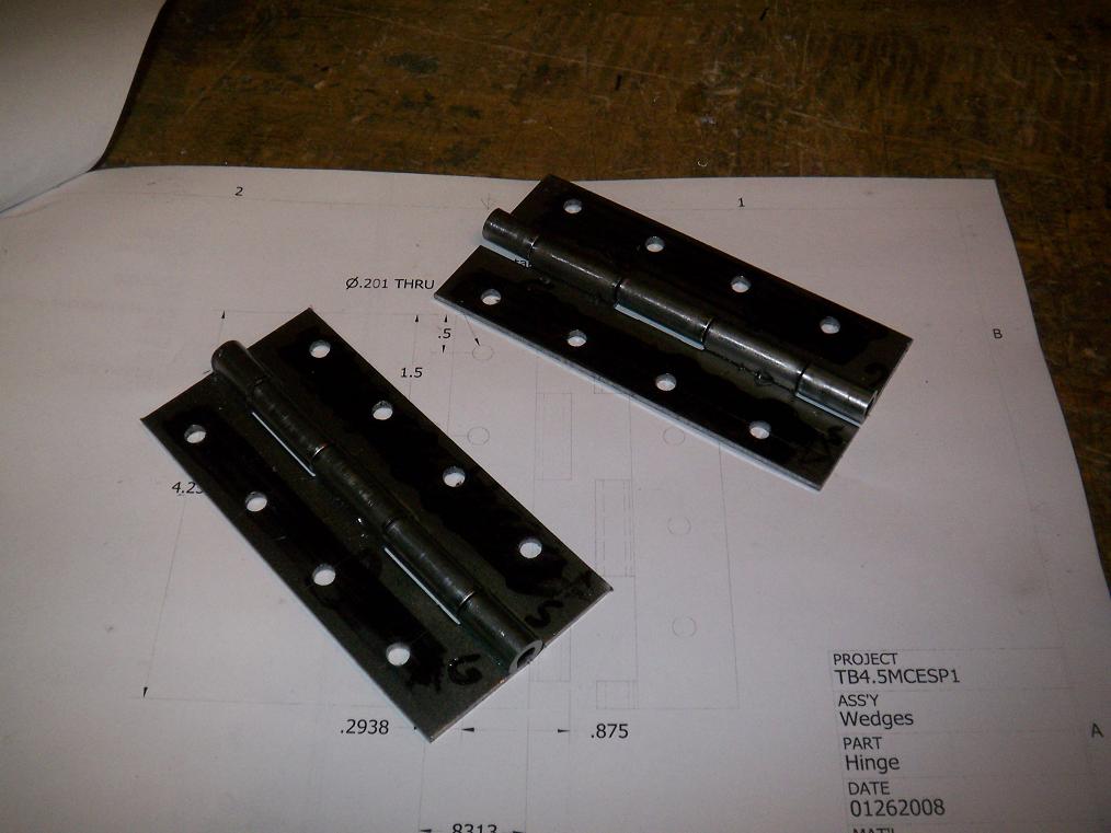 Hinges drilled. You may notice that they are missing the pins. I intend to use some hardened 3/16″ steel rod as “pins” instead of the cheesy stuff that came with the hinge, which I could bend a 4 inch section thereof by hand. The hinge seams will also be tack-welded shut to use the extra strength. Also, I might incorporate “nutstrip” along the inside of the bot at the attachment points to lessen the likelihood of losing a wedge even more.
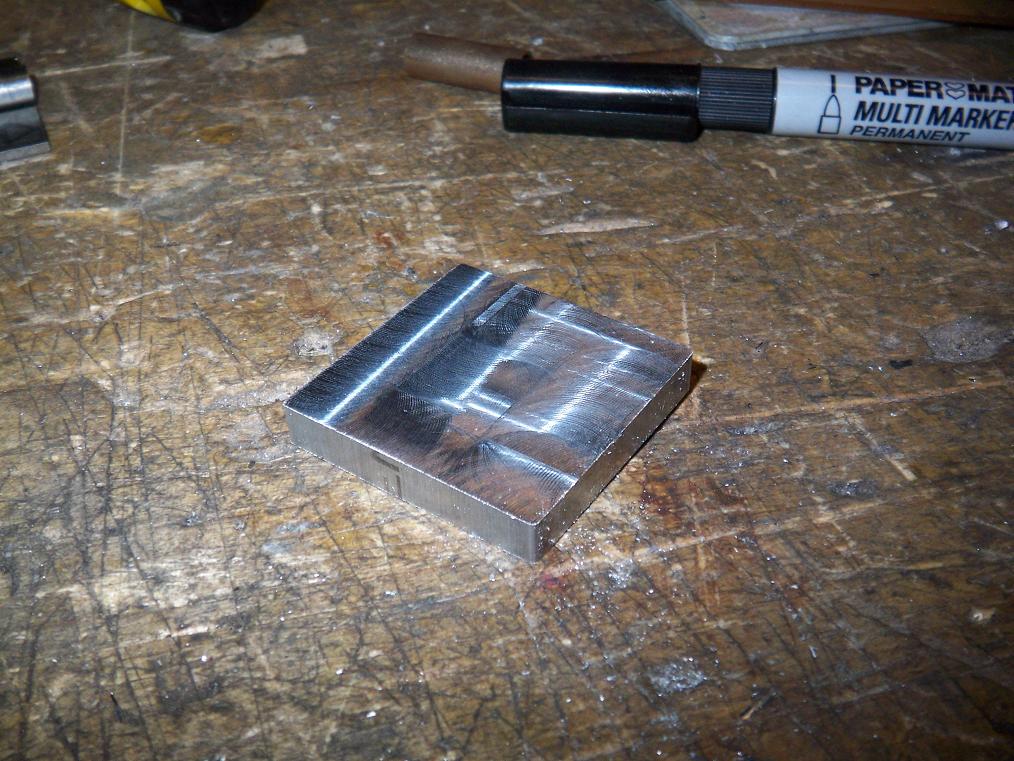
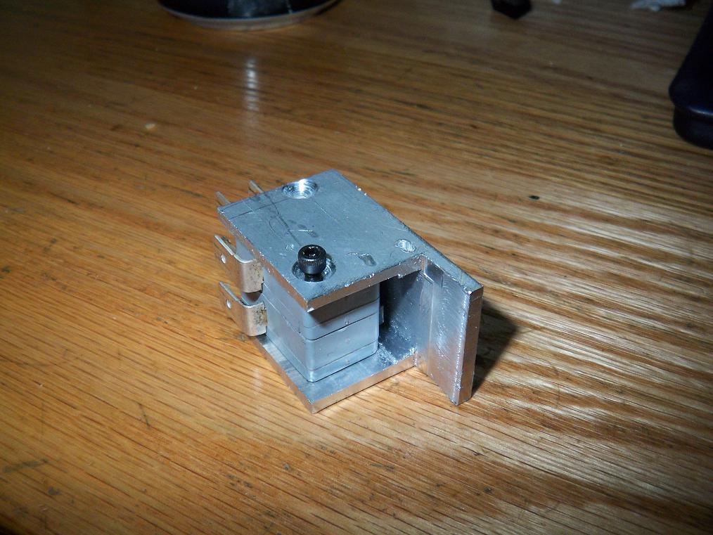 The almost-done frame for the überswitch. In MCE, this was a hack with some aluminum angle, washers, and spare standoffs. I’m giving the switch a proper frame in 1″ aluminum channel milled to the appropriate shape. The key slot hasn’t been made yet, because…
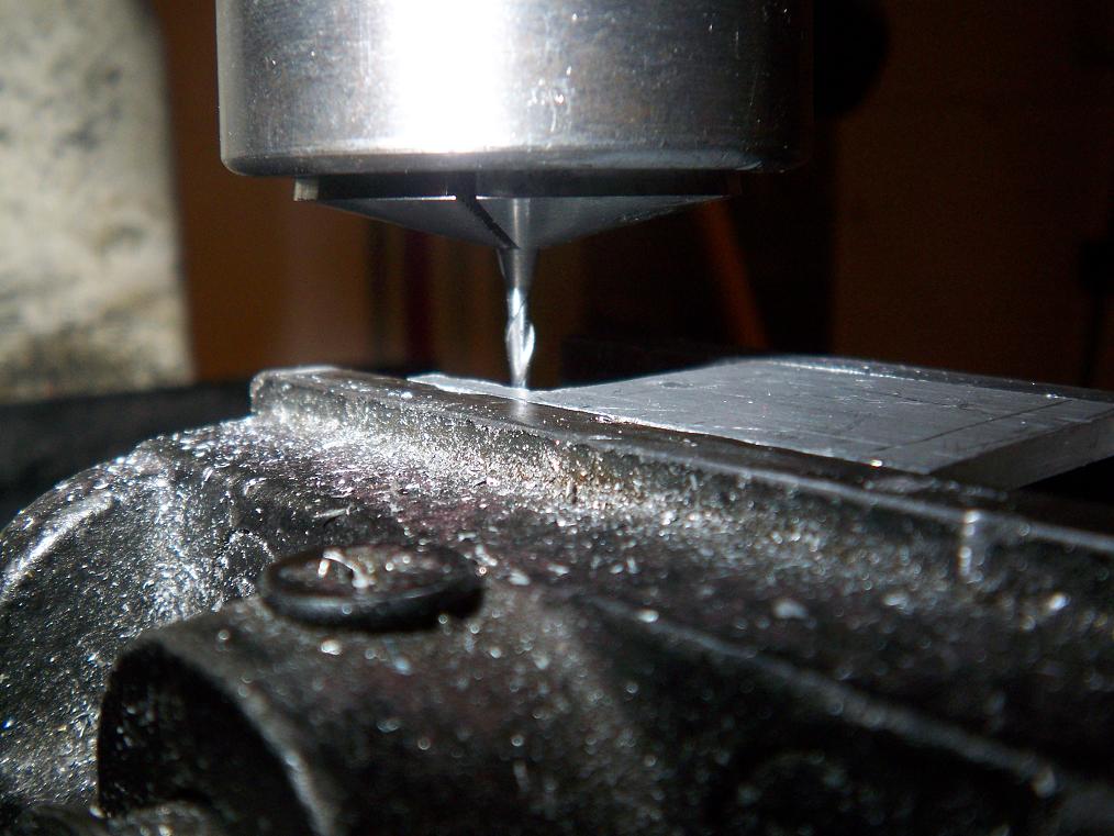 …I couldn’t find a 1/8″ endmill. There was a broken one, but that doesn’t count. I did find this tiny 2mm endmill that I briefly started using to cut the key slot before realizing that the machine can’t run anywhere close to the speed the cutter needs. Something like this needs 5 or 6000 RPM or more to properly use. I stopped before causing some damage or breaking the tool. MITERS has 1/8″ endmills for the Bridgeport, so I’ll swing by some time later.
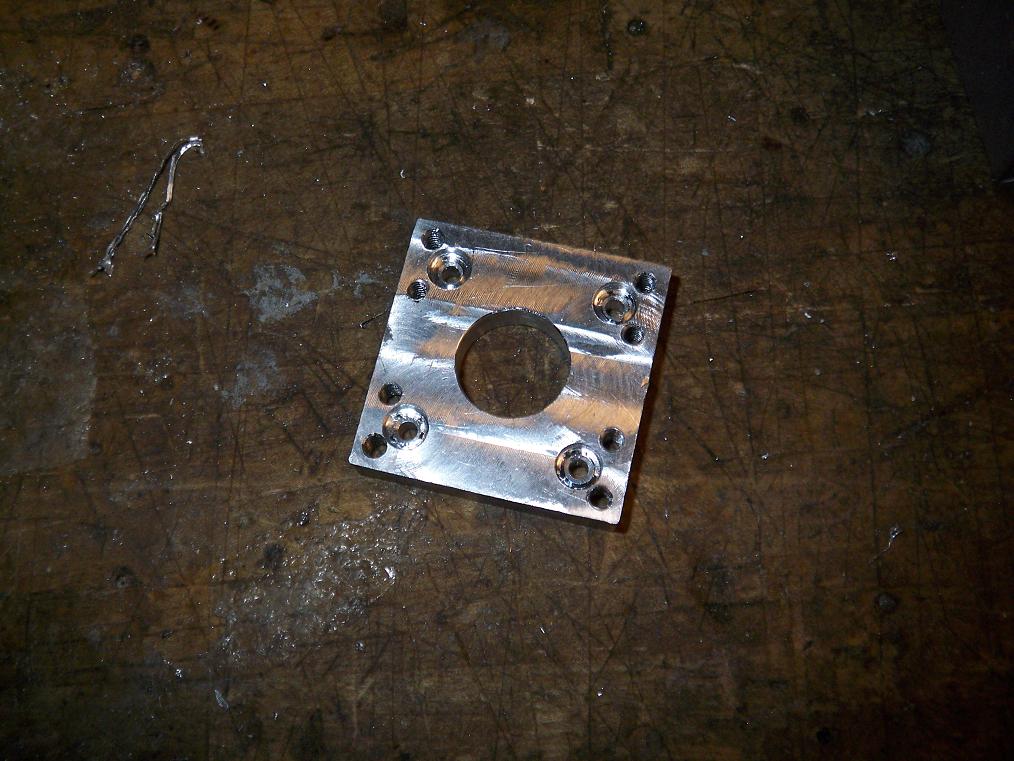
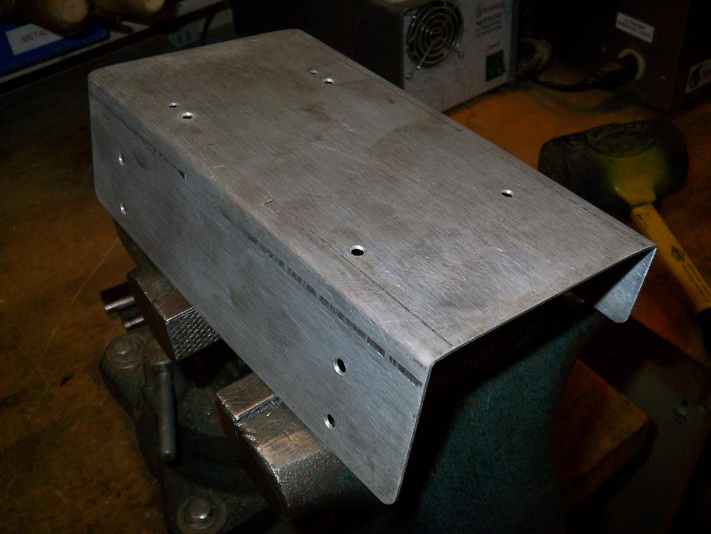 A few days ago, I decided (after almost blowing up my 12v power supply from a dead short) that I really needed to integrate my new charger and its power supply into one unit, along with accessories, to prevent from having a clusterfuck of wires every time I need to charge a battery. The prototype was made from GIANT LAZER’D acrylic, but acrylic does not cold-bend and I couldn’t find a strip heater. So I used the prototype as a template to transfer the hole pattern onto some .1″ aluminum.
The sheet was then folded on the Media Lab sheet metal device. It’s only built for 20 gauge steel, and here I am trying to bend .1″ thick aluminum on it. It did NOT go smoothly. But in the end, what brute force I could dish out did work, and there were no heartstopping cracks or odd noises from the machine.
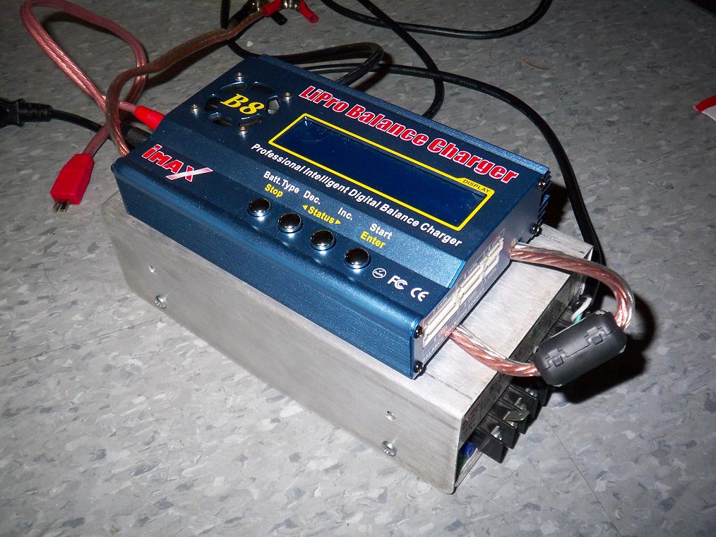 Test assembly. I’ll probably mount terminal strips, fans (the charger does get hot despite what its 40mm fan tries to do) and other accessories as necessary.
Great, now that almost everything else is done, I just NEED SOME TIME ON THAT WATERJET! I don’t have a ML network login and so can’t hop on and do it just any time. Fortunately, the nice folks as the ML are always willing to help out. We’ll see where this week leads.
Bot on!