About now in most of my projects is when things start breaking, not fitting, or not working. Let me be the first to say…
AAAAAAAAAHHHHHHHHHH FUCK FUCK FUCK FUCK FUCK FUCK FUCK FUCK FUCK FUCK FUCK FUCK FUCK FUCK FUCK FUCK FUCK FUCK FUCK FUCK FUCK FUCK FUCK
There. The short story: The bot doesn’t work.
The details: The arm jams, the Spektrum Rx doesn’t communicate with the Victors, and the SyRen25 arm controller current limits really fast. And the wedges still aren’t done.
Anyways, some quick pics from the last few days…
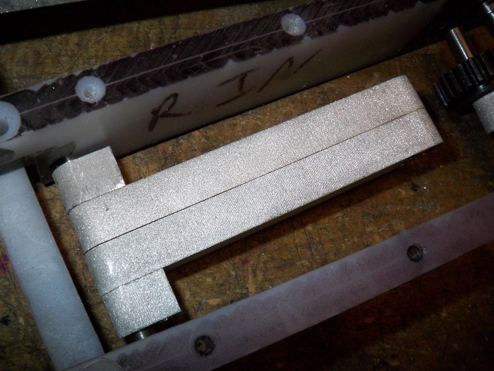
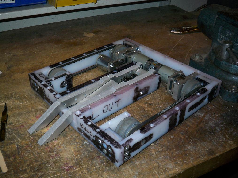
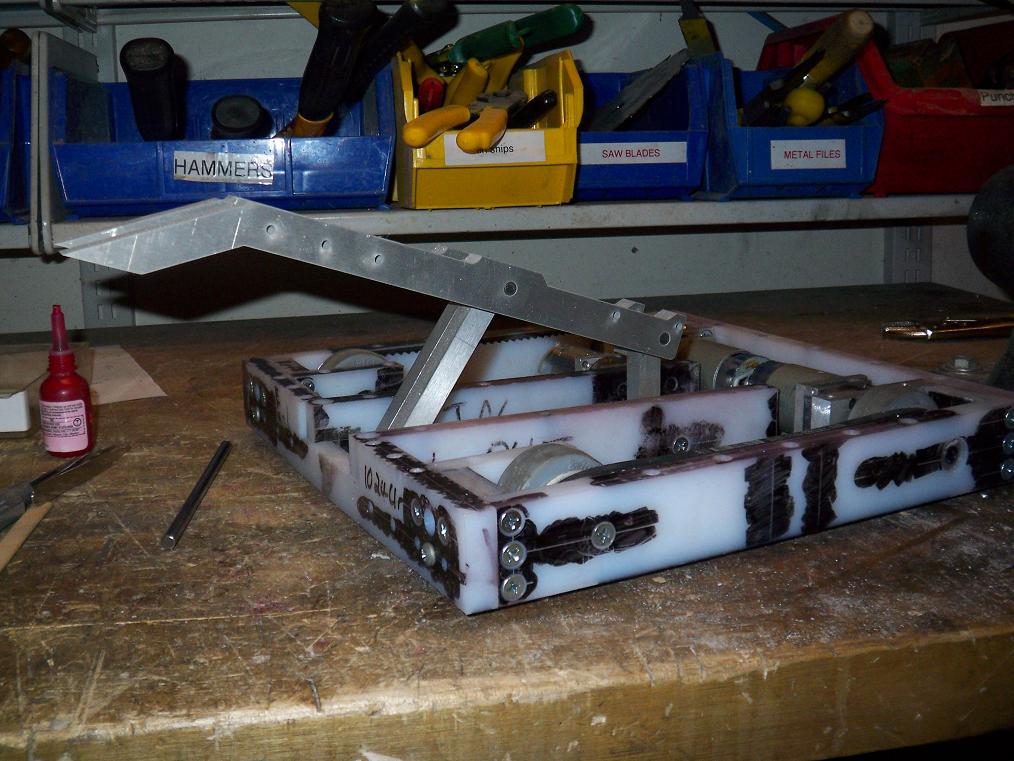
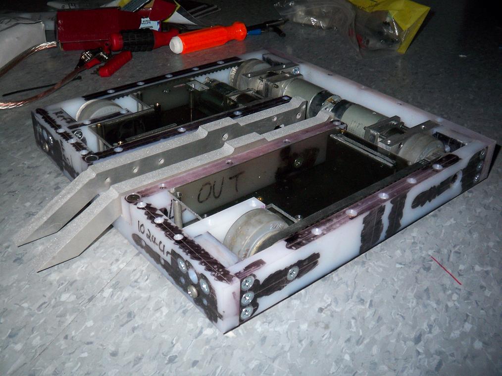
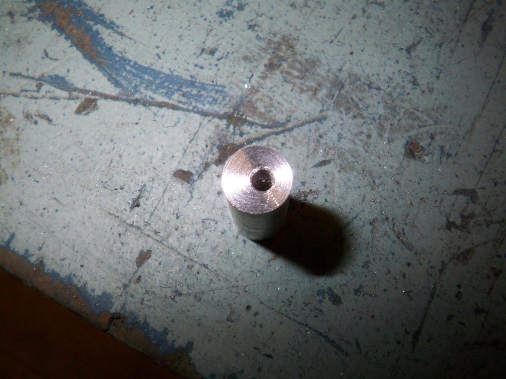
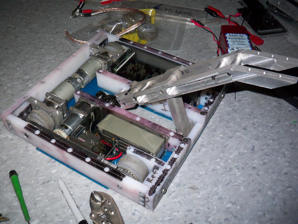 Here’s another gratuitous bot-shot.Several things have been done to the arm structure, namely the addition of ginormous inter-beam standoffs and the channel cuts in the beams themselves. The standoffs keep the arm links an exact distance apart and also gives the structure more integrity. The channeling was to reduce weight.
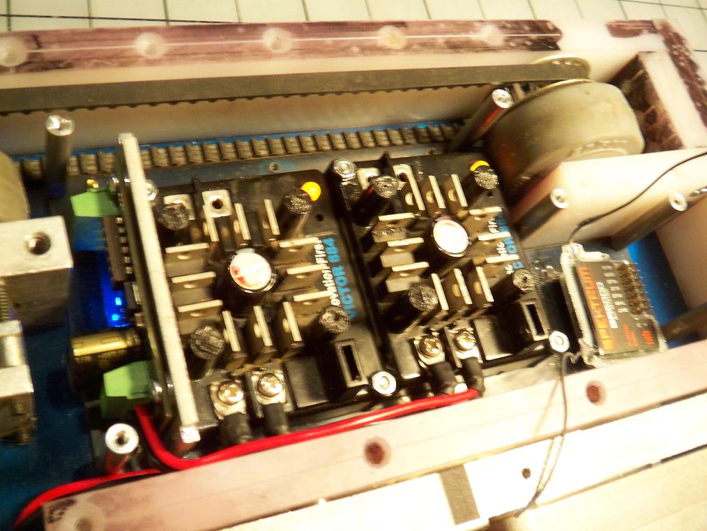 Preliminary wiring gives the green (okay, orange and blue) light for the controllers. Yes, they work.
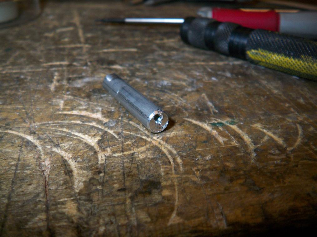
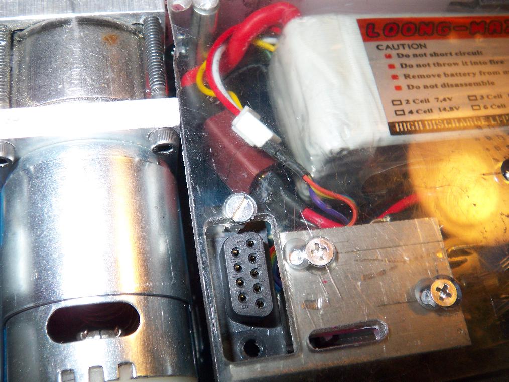 A botcessory that I cooked up during the design process was to create a charging port. I wanted to find some way to charge the battery with balancers without taking the whole bot apart to get to the connector, so everything was routed through this DB9 connector. The charger will have its own integrated plug. Shove into top of bot, done.
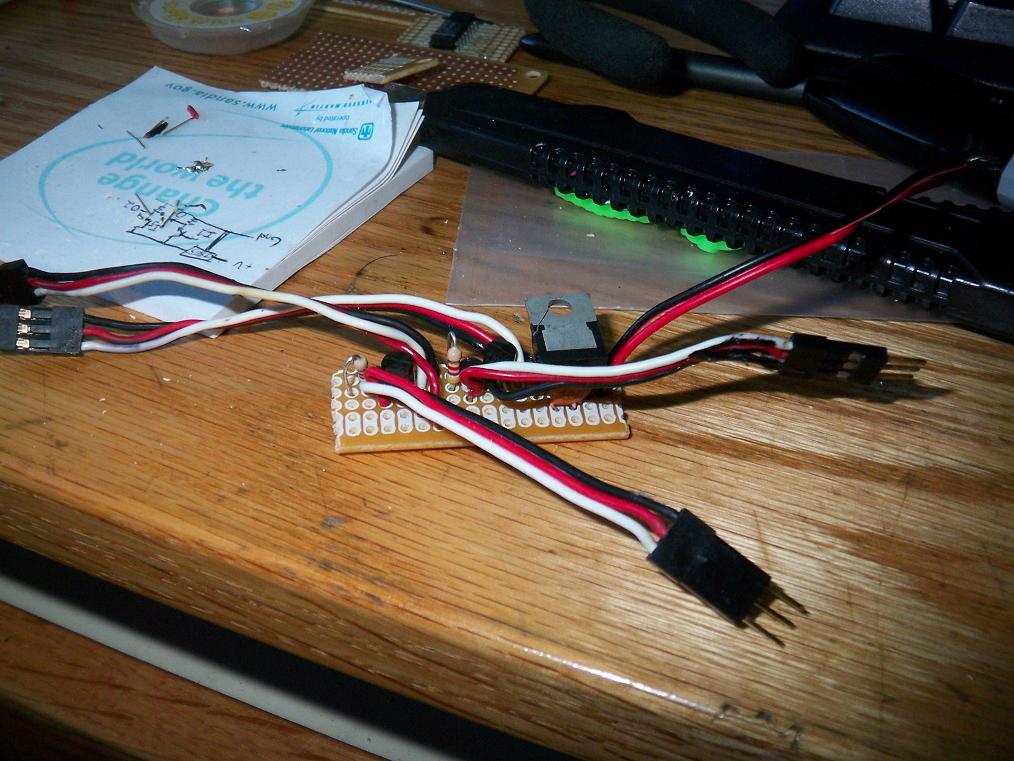 This is Ghettobooster. It’s a 5v regulator strapped to some signal transistors and the PWM cables. It sits between the Spektrum receiver and the Victors and amplifies the signal such that the Victors actually notice the receiver.
It worked great the first time, but now nothing works again. And I’m out of small transistors.
So, onto the problems that I need to solve before Wednesday:
1. Everything bends.
UHMW especially loves bending. The torque from the motor combined with the momentum of the whole arm assembly when it’s traveling at .1C causes the external spur gear stage to bend away from eachother until there is so much force between them that even the motor can’t get things back down. This is a direct consequence of having an overhung gear shaft combined with a UHMW motor mount.
Unfortunately, there is no easy way around it at this point. The simplest solution is to cook up some sort of external support for the shaft at the gear, but since said gear is trapped between two arm links, that’s rather tough.
The other solution is to get rid of the pins holding the arm at the upper position such that the links can keep going further. This gives me more response time, but doesn’t solve the jamming issue.
I can also try some sort of software limit using a “signal interceptor” microcontroller to read limit switches, some sort of optical interrupt, or a hall effect switch with a magnet strapped to the arm. I have some AVRs. I have a parallel port ghetto-burner. This is a possibility.
2. Victors are the Cadillacs of ESCs
And they take some serious power to drive. Victor 884s are opto-coupled controllers that apparently have opto-couplers the size of a capybara. Not all receivers can output enough current to drive them, which is why Victors frequently need buffers. So I made Ghettobuffer earlier, which worked for a few minutes and at least allowed the bot to putz around the ground, but now… it doesn’t work again? What, do I really suck that bad?
I’ll need to figure out what’s wrong or get some commercial inline R/C signal amplifiers ASAP.
3. Overprotective ESCs are like overprotective mothers and overprotective governments
The SyRen25 has regenerative braking, temperature and current limiting, and the ability to be controlled by smoke signal. It’s almost unkillable by conventional means, but that current limiting also means it quickly clamps down on the power that the lifter motor can produce. The 4-bar arm in TB is very close to the bottom toggle point due to the shape of the bot and it takes a significant burst of current for the motor to generate enough torque to lift another 12lb object. The SyRen detects this and thinks I’m shorting the outputs into eachother. Result? No lift.
At least I can blow up the Victors when I want to. Not that I want to. Oh snap, please don’t let that happen.
The bottom line is, if the bot is not running by Wednesday night, I am not going to Motorama. That’s right, I’m skipping the event. It’s not worth missing two days of classes, including one lab, if the bot is going to be flakey and dysfunctional.
We’ll see where this goes. SP1 is almost there.


