So now that classes have begun, I’ll have slightly less time to work on the bot. But it’s getting close. It’s getting Real Closeâ„¢. Here’s the conglomerate update over the past three days or four days.
 The arm ESC in its “riser card” whose profile fits into a slot in the left side EBay. I actually think this is a great arrangement for single-board controllers, and might use this layout in future projects.
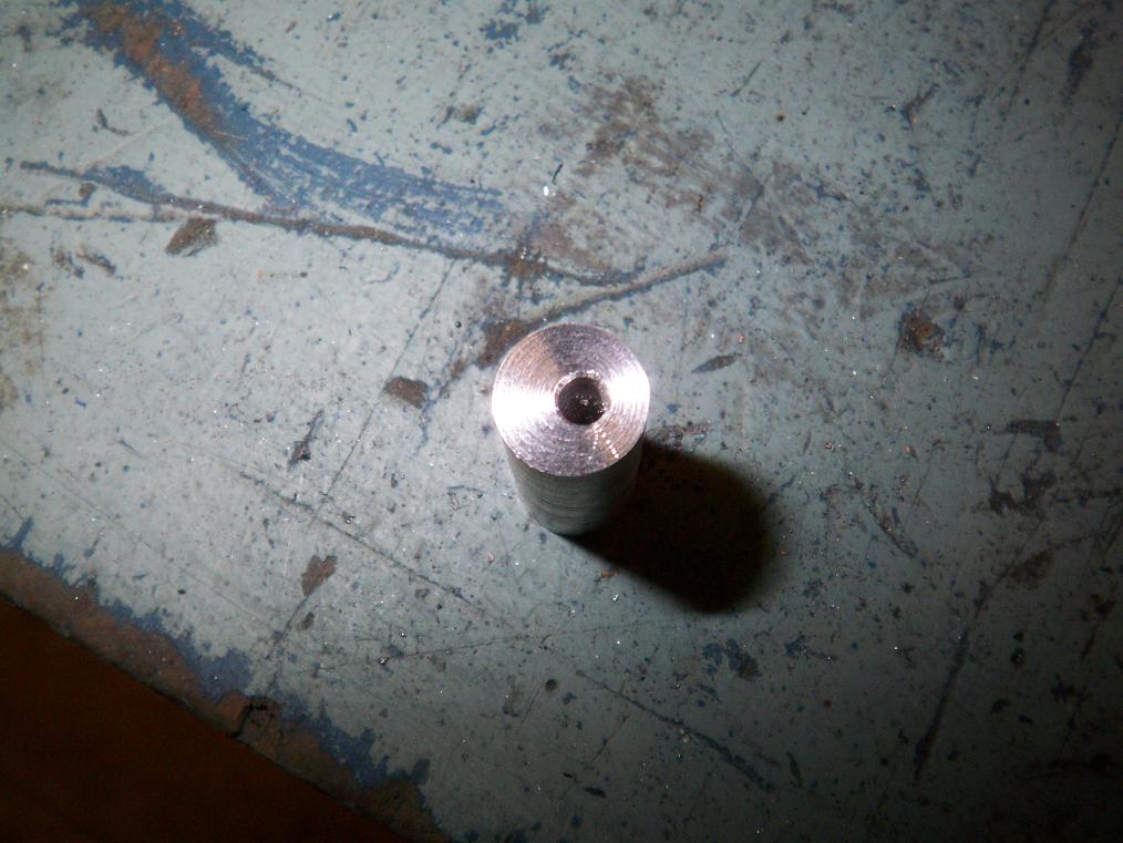
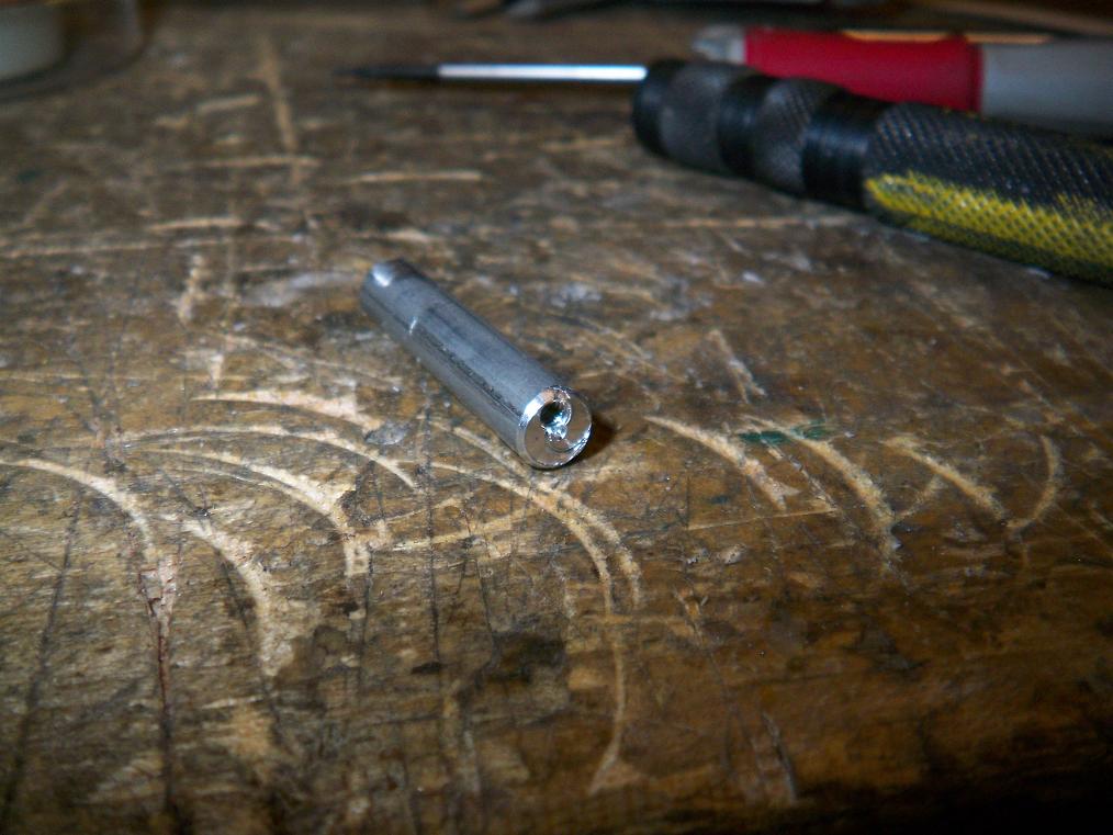 One of the standoffs is really fucked up. Wow, finally an off-center machine product that I wasn’t responsible for!
It also says something about the quality control at whichever company it was that made this. Oh well, can’t catch ’em all.
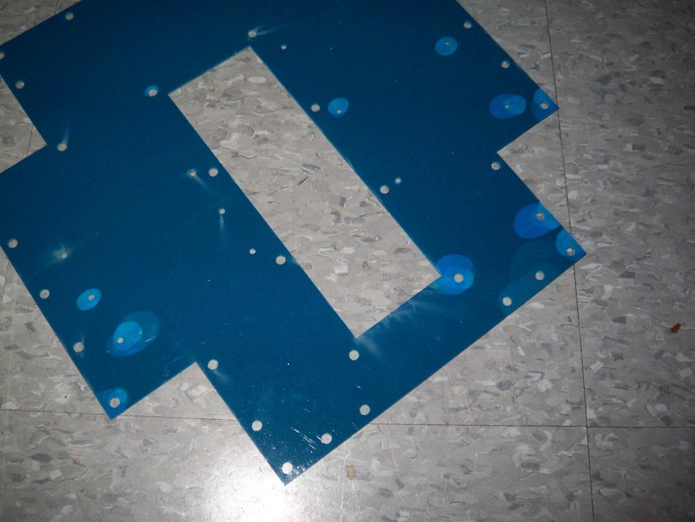
 Both assembled EBays. These pieces also got some rough handling by the waterjet. As a result, I had to move some of the standoff locations. The empty holes are visible in all the plates.
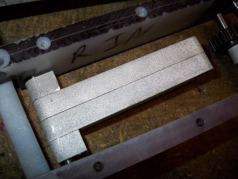
 Hey, a fitted arm link. This is the rear driven link. The gear will have additional holes drilled to reduce weight. Or, if I can get ahold of a rotary table, it will have some bits milled out of the core. The latter method retains more integrity under torque.
 The front link assembly. In retrospect, I’m not sure why I insisted on putting the little linklets on the ends. Symmetry, I suppose. And, at least for the front link, to distribute loads over a wider area.
All are attached together with some counterbored 4-40 screws.
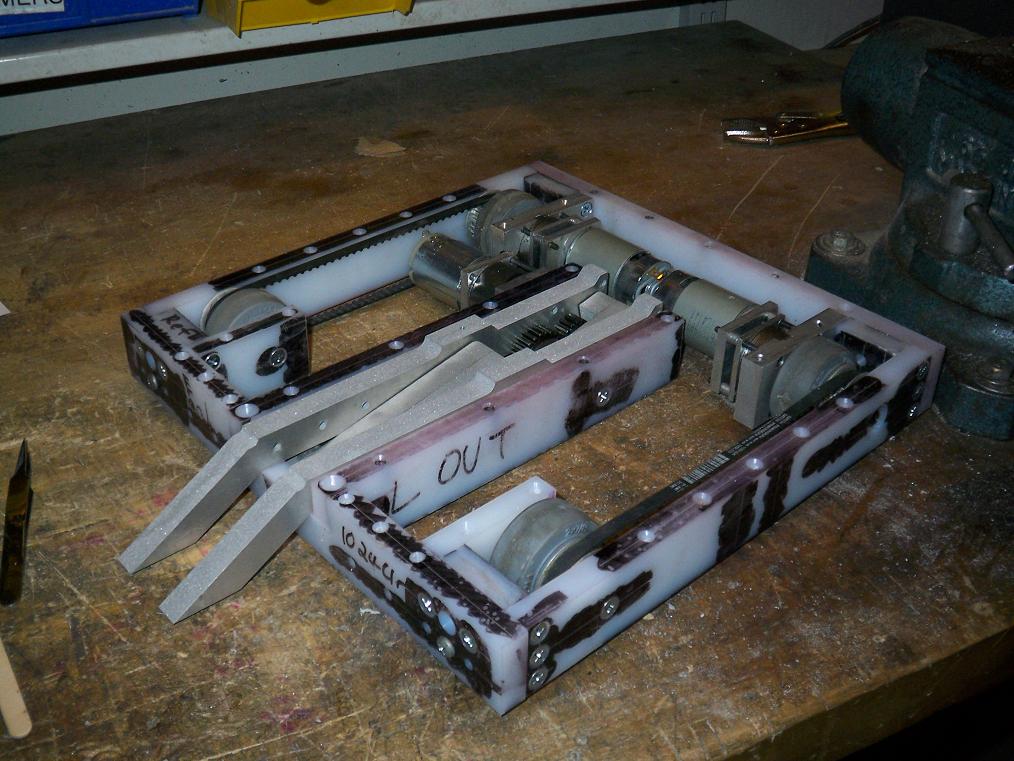 A quick toss-together to check for fitting…
 And some movement for visualization and to check for interference.
 Test fitting the EBays in their final locations. They actually add a great deal of rigidity to the chassis in terms of side-to-side deflection since they take up the entire length and width of their cavities. In fact, mounting them is a very light press fit against the chassis rails.
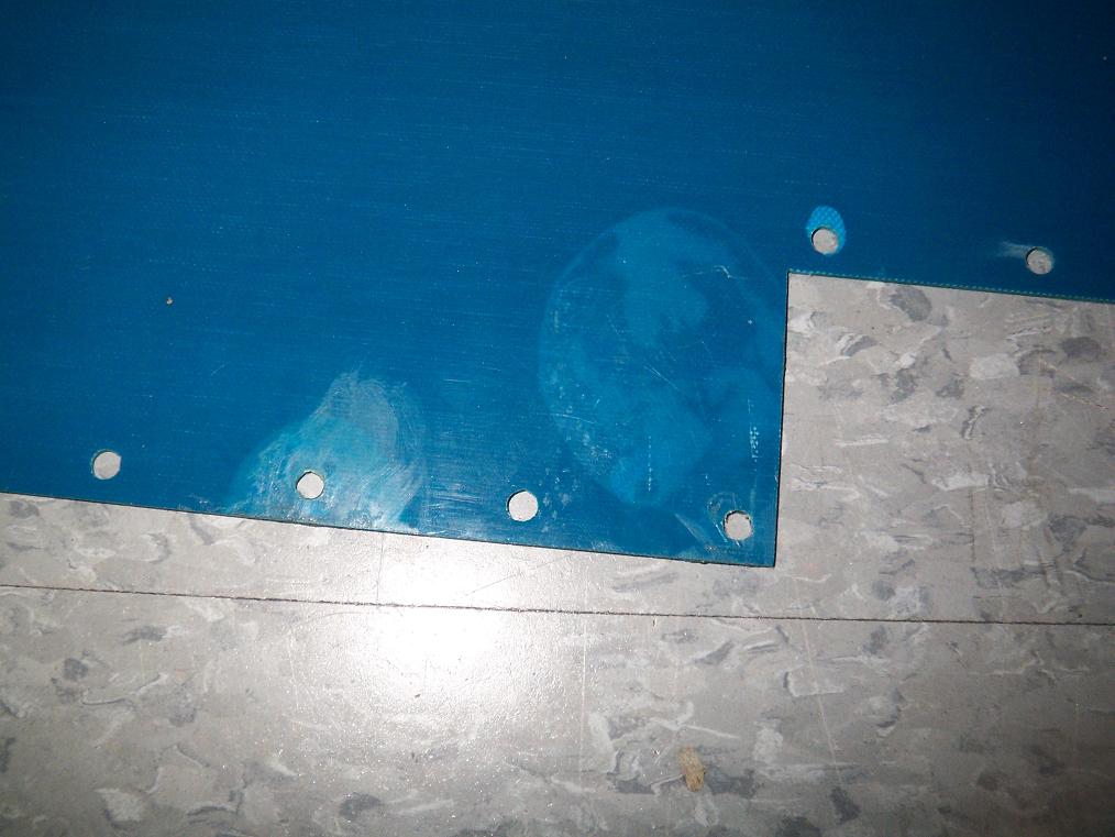
And now some adventures with garolite delamination. My method of choice ended up being using water-thin CA glue and wicking it between the layers such that they filled part of the interstitial bubbles. I locked the sheets in a vise after each bubble fill to let it set with the layers pressed together. This worked great for the most part, but some of the large bubbles actually had abrasive grit stuck in them and could not be closed all the way. No matter.
The small hole-area delaminations were filled after I countersunk the holes such that I could wiggle the CA nozzle into them.
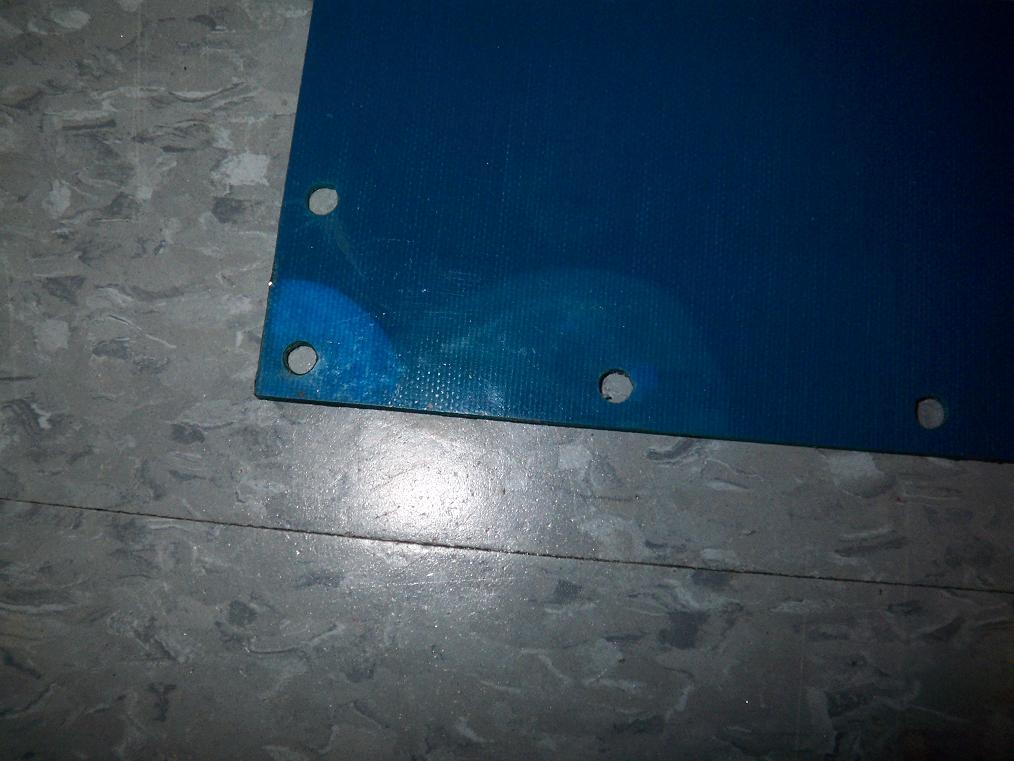
 Holes all countersunk. I went a little shallower than what the screw head called for in order to retain the strength of the material around the holes some more. Hence, the screws stick up very slightly above and below the bot. Not enough to cause trouble.
I also went over each of the countersunk areas with CA glue to seal the joint and hopefully prevent “transcendental garolite syndrome” which has been seen on TB since build 4.0 in 2006 – where the countersunk screw head magically passes through the hole without (visible) damage. It’s the strangest thing ever and I have no explanation for it besides the break occuring so quickly and cleanly that it snaps back together and I don’t see the separation.
 Fitting the chassis along with top and bottom plates together. Yep, it fits.
 Components in their final positions, but not yet mounted. The battery is slightly too tall to fit between the plates, but they have foam spacers which can be compressed somewhat. Otherwise, everything fits as designed. I love 3D design.
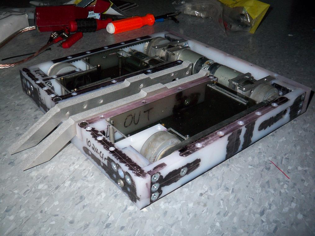
 After the semi-successful planing operation described yesterday, it’s time for a fitted powered test! Things were a bit rough and I didn’t have real 1/4″ pins, and so no heavy lifting was done. However, the mechanism moves as planned.
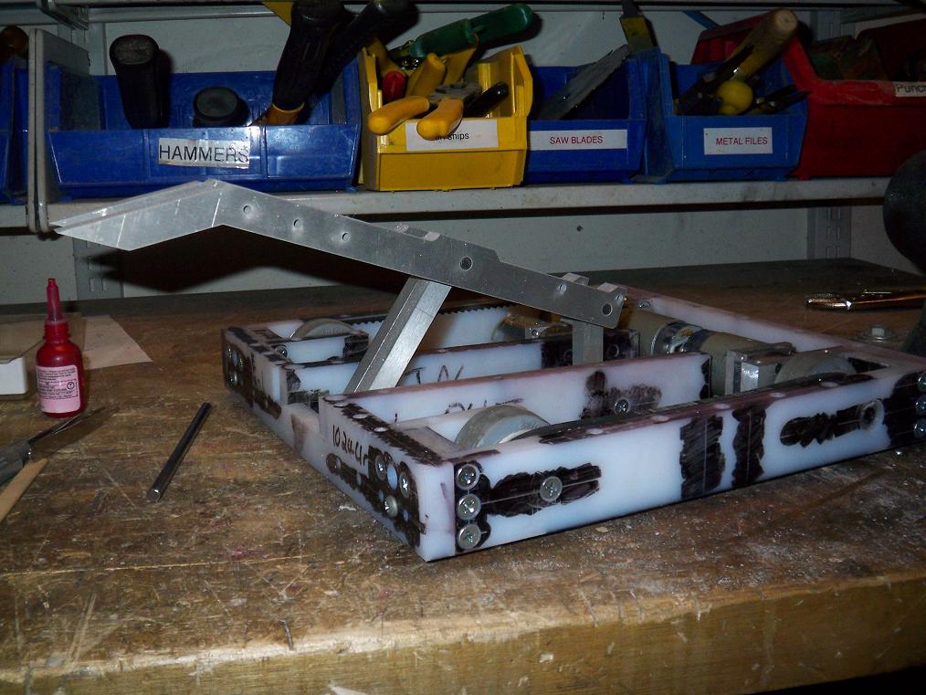
Well, mostly. The arm does have a “hyperextension” mode where the driven link goes past the “straight point” pictured here. Past TB arms have had built-in hard stops at this point since they were C-channel designs. However, with this two-beam system, there is nothing preventing the link from traveling past it. I did include hopes to put in pins that act as hard stops, but I suspect the hyperextension might come in handy in some matches – the arm goes almost completely vertical.
However, if I don’t stop there, the linkage has enough degrees of freedom to actually swing back around the underside and lift the bot off the ground. This underside position is also one that cannot be recovered from using motor power, since it is a toggle position. Uh oh.
Is it time for some software limits?!
Or better linkage design?!
Bot on. Like, seriously. Moto is a week and a half away.
