Mecha-Turkey says hello.
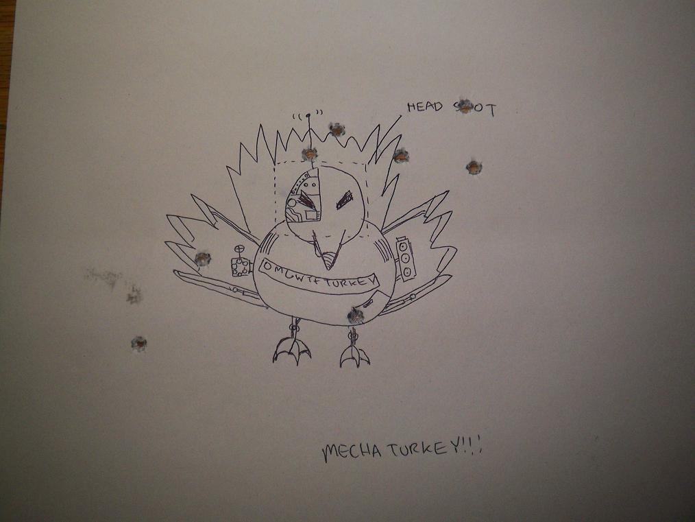
I’m taking a target shooting class (Yes, Charles with guns. Run away quickly.) , and this was just something fun done before the wtfkthxgiving holidays. Unfortunately, I missed the head shot, but hit the H in “shot” dead on. This was under a half inch tall from 50 feet away and I’m not particularly steady. Mecha-turkey would have mowed me down with its minigun and rocket launcher.
In somewhat related news, I’m going to take the opportunity of missing the opportunity to fly back to Atlanta and get some work done on the wheelmotor. These stupid “class” things really get in the way of building cool stuff. As I had some spare time but no materials for most of the past few weeks, I did some more design work to optimize and simplify some things.
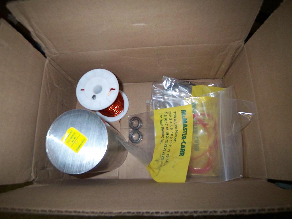 A box of McMaster stuff. Some of the Media Lab guys are starting to take note of the work I’m doing, and so have extended some lifelines, so to speak. The 3.5″ aluminum round is for the motor body parts. The wheel will be supported by the 15mm bearings.
I just now realized how ungodly huge 16 gauge magnet wire really is. Not that it won’t work – there’s plenty of margin around the stator – but I’m going to have no hands left after winding 30 stator poles using it. I’m not sure how this guy does it with monster wire like this, but… good freakin’ robot Jesus. The ML has miles of 20 gauge I might just end up paralleling to wind the first motor. It’s a semi-prototype anyway, and those few efficiency points I might lose because of wire choice – oh well.

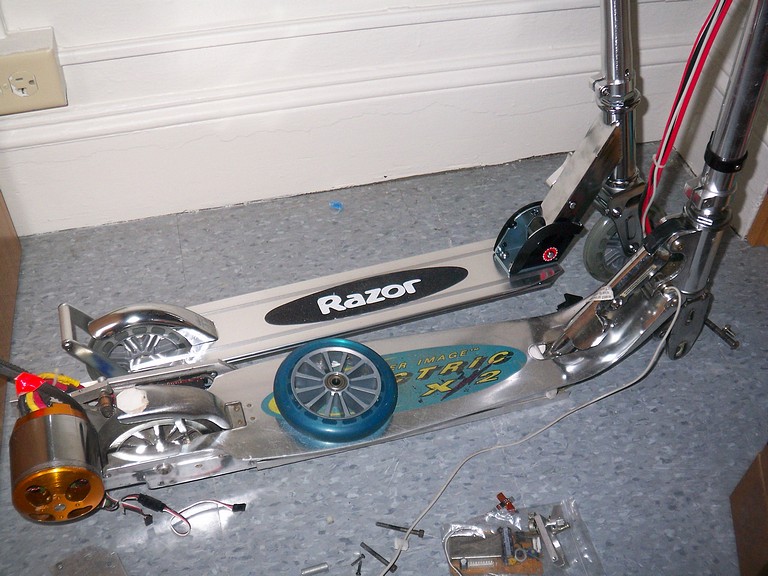
Something else I fiddled around with was the idea of adding rear suspension to the A3. As much as the front suspensions on the scooters try to absorb the impacts of sidewalks and bumps, the rear is stiff and unforgiving. It didn’t help that all my electronics were located right on the rear wheel centerline before, and so every bump in the street was a major shock.
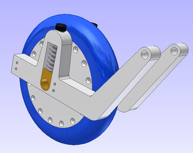
This little module will slide and mount inside the aluminum T-tube that forms the chassis of the A3. I particularly like the design of the A3, because you can mount and number of things just by sliding them onto the channel and locking with screws from the side. I’ll have to trim the metal around the back wheel a bit, but that’s no issue.
By examination, the “shock towers” sort of interfere with operation of the rear fender brake, but I’ll actually have to build it to see those tolerances.
The sliding block will be brass, bronze, or some other metal better at being a bearing than aluminum, which tends to gall and gunk everything up. It will replace the entire axle spacer assembly.
Springs will be some small die springs from McMaster, rated to 250 pounds per inch of throw. I’ll only have about half an inch of travel because of the springs’ solid length, but that’s enough. At a total of 500 pounds per inch of travel for two springs in parallel, it should not be too floppy. 500 sounds like alot, but you can easily exert that much force by jumping, and a good bump will certainly exceed that instantaneously.
So it looks like if I’m building anything, I’m building the whole thing. The ML guys are interested in seeing the motor itself first, though, so that’s number one on the priority list. I’m also using the same “slide-in module” design for the electronics bay and battery pack. It’s quite handy.
Bot on!