I remember two weeks ago when I said that I would build nonstop through the break; anything I could think of, and come up with more things if I ran out. Anyways, that totally went to hell. But progress is slowly coming.
I’m in the process of completely redoing the Snuffles Reloaded wheelmotor. The previous one was okay for getting the concept to materialize into something solid, but was done across 3 different machines and with little regard (or ability) to center the workpiece properly.
There are also some design changes this time around. Most notably, I’m redoing the magnet can out of steel to better fit the very strong magnets that will be used, as well as to simplify things.
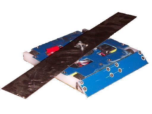
 The finished product. This was the single most torturous piece I have done yet. Steel of this diameter needs to be turned reeeeeeeally slowly. I mean like 70RPM slowly. It was very hard for me to keep my feedrate down (because I’m used to small aluminum parts), and if I went too fast, I would just be cutting shallow screw threads.
Not to mention that it was a hot-roll steel pipe that I carved this out of, so the steel was total shit and was gummy. The surface finish is horrible, but it’ll live. The perimeter holes were put in on a CNC machine (most awesome thing evar, only matched in awesomenss by a 5-axis abrasivejet. The two combined can carve the laws of physics and grammar such that they can both be most awesome.)
I’ll do the aluminum parts later. I might possibly redesign some of the internals to make the parts less weird.
In TB4.5MCESP1-related news, the arm controller came.
 Ooh, shiny. This is a Syren25 single-channel controller from Dimension Engineering. It’s a nice piece of work, and supposedly features regenerative braking. That’s hardcore. So having opponent bots backdrive TB4.5’s lifter could actually be a good thing, but they should do it slowly and gently!
 Since I was going to remount the ESC on my own heatsink plate anyway, I decided to take a look at the underside where the driver chips are.
O GOD WAT
NO! NO NO NO NO…. For the love of Robot Jesus Michael Fizgerald Jackson Christ! SO-8 surface mount FETS?!
I am SO GLAD I’m mounting this thing on a plate of aluminum that weighs more than it does.
I hate those tiny SMT FETs. Especially when the manufacturer (generally of brushless controllers) use like 20 in parallel to get a decent amp rating. What money and weight do you save then?
It’s even worse when you listen to the chip maker who says a 25A part is a 25A part. The SMT has absolutely no thermal mass and no capacity to withstand momentary overload. In fighting bots, you NEED THE OVERHEAD. I’m sorry, I will NOT run 25 amps through this thing for any extended length of time, and am very glad the arm is an intermittent duty cycle.
I’m making my own ESCs from now on, or I’m never building another robot of any kind.
Oh, and the heat spreader plate doesn’t contact the driver chips. That’s even less of a 25A ESC. DE might want to consider backing off the pressure a bit on whatever press that is stamping the aluminum sheet.
Anyways, time to actually start building the bot. The carbide teeth on the miter saw’s new blade are slowly subliming, so it’s best to use them while they’re still fresh.


