The calm before the storm has arrived. About a week from now, I’ll probably hole myself up in my room and prepare to attack four final exams in four consecutive days. If I survive, I’ll post.
Anyway, tonight was “chill night” after the rush by professors to get the last bits of work and final-exams-before-final-exams in. By chilling, I mean heading to MITERS and, after collecting as much balls as I could, hop on the lathe and work more on the wheelmotor.
The MITERS lathe is probably older than the cumulative ages of any randomly-selected 3 or 4 people in the room at any one time. It’s a medium-sized “South Bend” model, but is probably the single largest chunk of cast iron I have ever personally messed with.

After I got the hang of it, it’s actually a great machine. The tool selection is lacking, but I intend to raise the proposition of purchasing some tool bits and tool blanks.
There’s one thing I don’t like about it. It uses a “lantern” style toolpost that seems to have 8 degrees of freedom and can jiggle in any direction except the one you want. A forged tool holder sits on a weird-ass banana thing which sits in a shallow bowl. You have to hold down the bowl, the banana, and the tool holder, then tighten down the clamping screw. At once. Up hill, both ways, in the snow. It is evil. Then the end of the tool holder is a complete clusterfuck on its own, since that clamp screw likes to drag everything with it.
I ended up having to tighten everything down out of whack and then use a mallet to bash things into alignment.
Anyways, stuff turned out well.
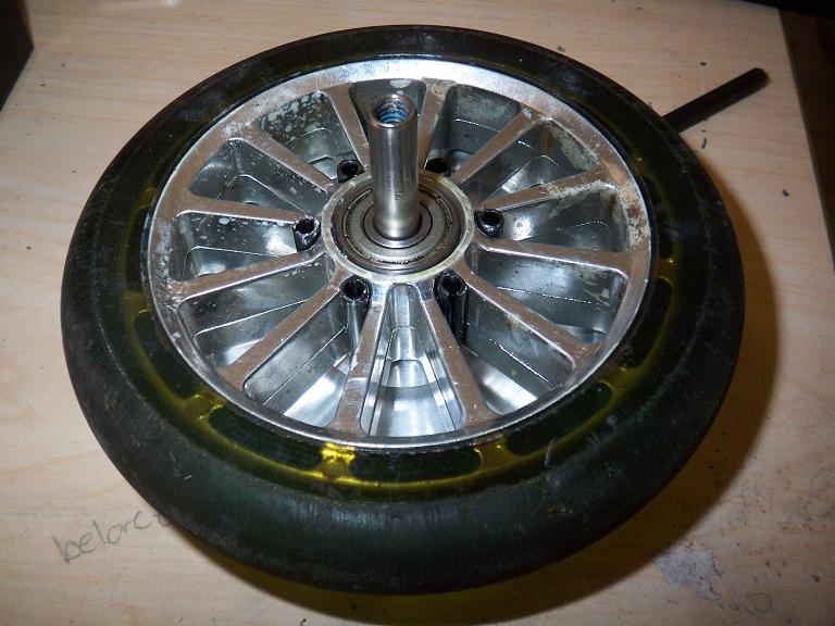
 The finished stator mount doohickey, with a bearing. Even with my eyeballing, newbie toolgrinding, and random bashing of the tool setup, it turned out well – most dimensions are within .005, which is just fine for starters.
Since I did not intend to disassemble this ever again, I press-fitted the shaft into the stator mount using an interference fit of about .01 inches. Three times what you are supposed to use. I stuck it in the biggest milling vise there was and cranked it with the biggest wrench I could find.
If this comes apart, I probably have also.
 On a related note, BATTERIES! Here’s two lithium polymer packs I snagged off EBay. Each pack is 11.1v, 3900mAh. Downside? They were 10C. That’s what I get for going “ooh, cheap” – even though my application doesn’t call for military-grade batteries, I still need the newer 20-25C packs for the low-end acceleration.
Since 40 amps is unlikely to move even my ass around, I will probably save these packs for Test Bot 4.5 Media Center Edition Service Pack 1, under final planning for the 2008 competition season.


 The stator mount designed for the motor is a dished-in piece of aluminum with stubs on it to seat the bearings. However, I decided that it would be much easier to make the dish separate, then press the shaft through. It would involve less wrangling and maneuvering of the tool bit and simplify the process.