Project Deathblades: Turning up the Heat

Back in January, I first posted about Deathblades as a distraction from the January build season where I finished Cold Arbor. Since then, it has mostly been a background process. I put the anticipated motor parts in a box and sort of forgot about them for a while.

With the semester more than halfway over and the summer build season rapidly approaching, I went back to Deathblades and gave the project a little more thought. Armed with more background on how brushless motors actually worked, I began designing the skate motor around the salvaged copier stators.

Oh, yeah, back in late January, I put together an Instructable on building small hub motors. I’m a fan of intellectual property and product marketing propriety and all, but I also like DIY and individual engineering efforts. So, someone make my work useful and build a hub motor or something.

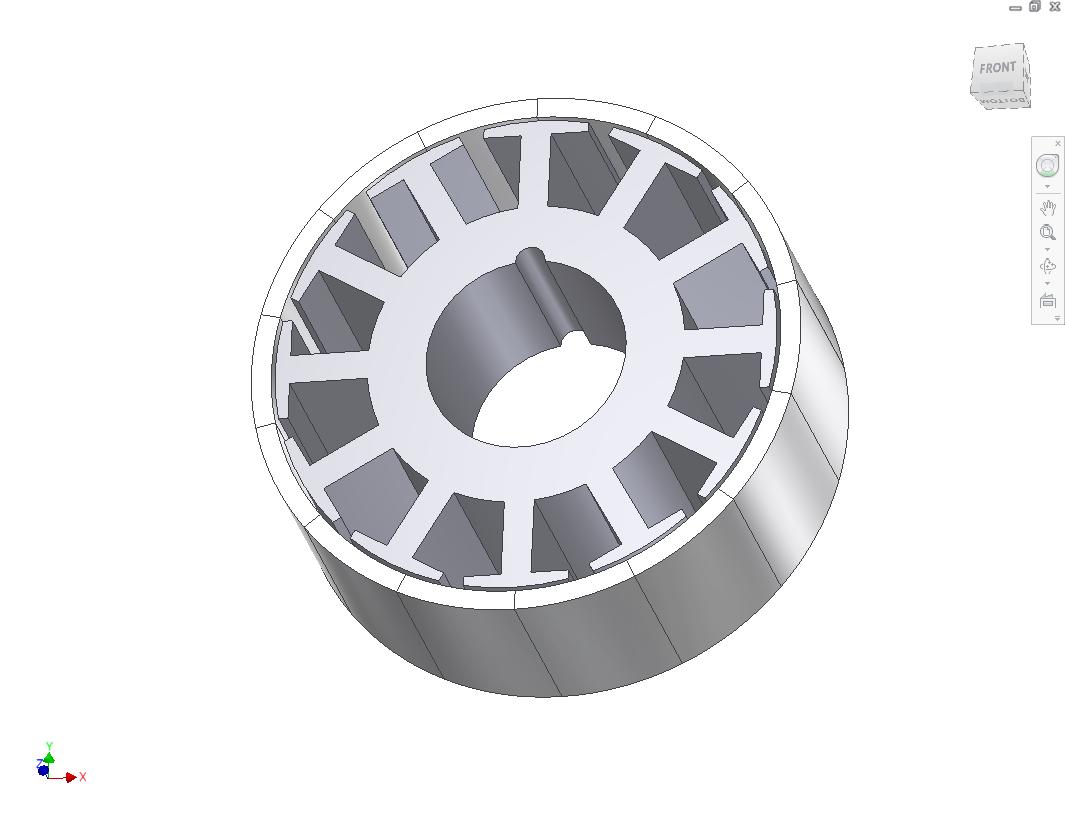
Let’s start with the basics. This layout is about the same thing I create for every 12 slot motor ever. Since I can have custom magnets made and delivered super-duper cheap, I have elected to skip fudging with flat magnets for now.  It’s just not worth the extra effort of making sure they’re all aligned when a full circle only costs a few dollars more.

I elected to keep the usual 0.5mm airgap and design in some 2mm thick 14-pole arc segments.

Altogether, RazEr’s motor is capable of cranking 4 or 5 Nm of torque, and it accelerates pretty well. I want to hit the same target with Deathblades, but since it will have 4 motors sharing that load, it should not be difficult. Average little dLRK motors like this seem to always have a torque constant of 0.2 to 0.3 Nm/A or so, provided you keep the turn count in the mid-double digits.

I discovered through 2.671 that NIBLR overestimates motor torque by about a third just due to the nonidealities that it overlooks. This is fine – I’ll just overspec the motor by 33% or so.

Leap of faith!!

Here’s revision 1 of the design, featuring the dual removable ring structure that I also designed into one variation of the RazEr motor.  The wheel is a 100mm skate wheel, specifically from the newest Razor scooters.  I chose them after taking dimensions from people around here who owned Razor scooters. They have a rather low tread profile compared to many 100mm skate wheels, which maximizes the motor diameter, and consequently torque.

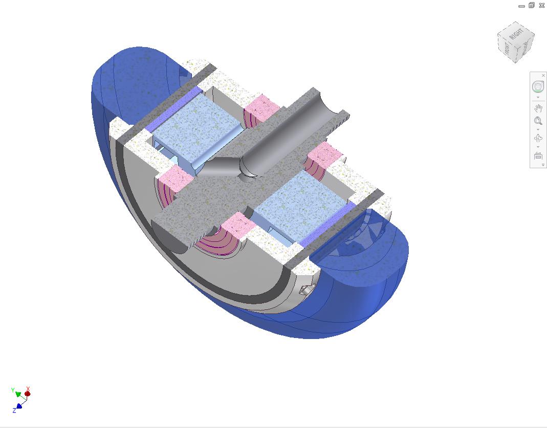
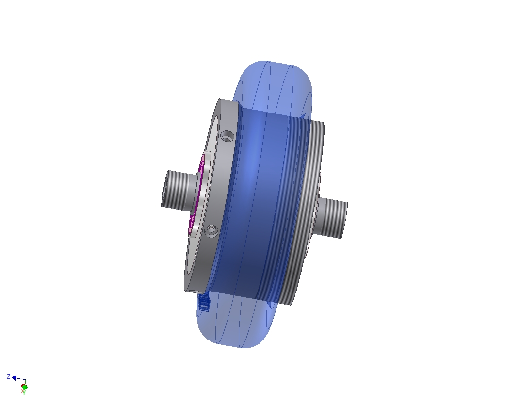
Here’s a cross section of the design that I made for the Instructables page. The skewed hole in the center is for passing wires out of the motor. Otherwise, the lightest blue shade is the stator core, the medium blue is the ring of magnets, and the pink things are type 6902 ball bearings.

A

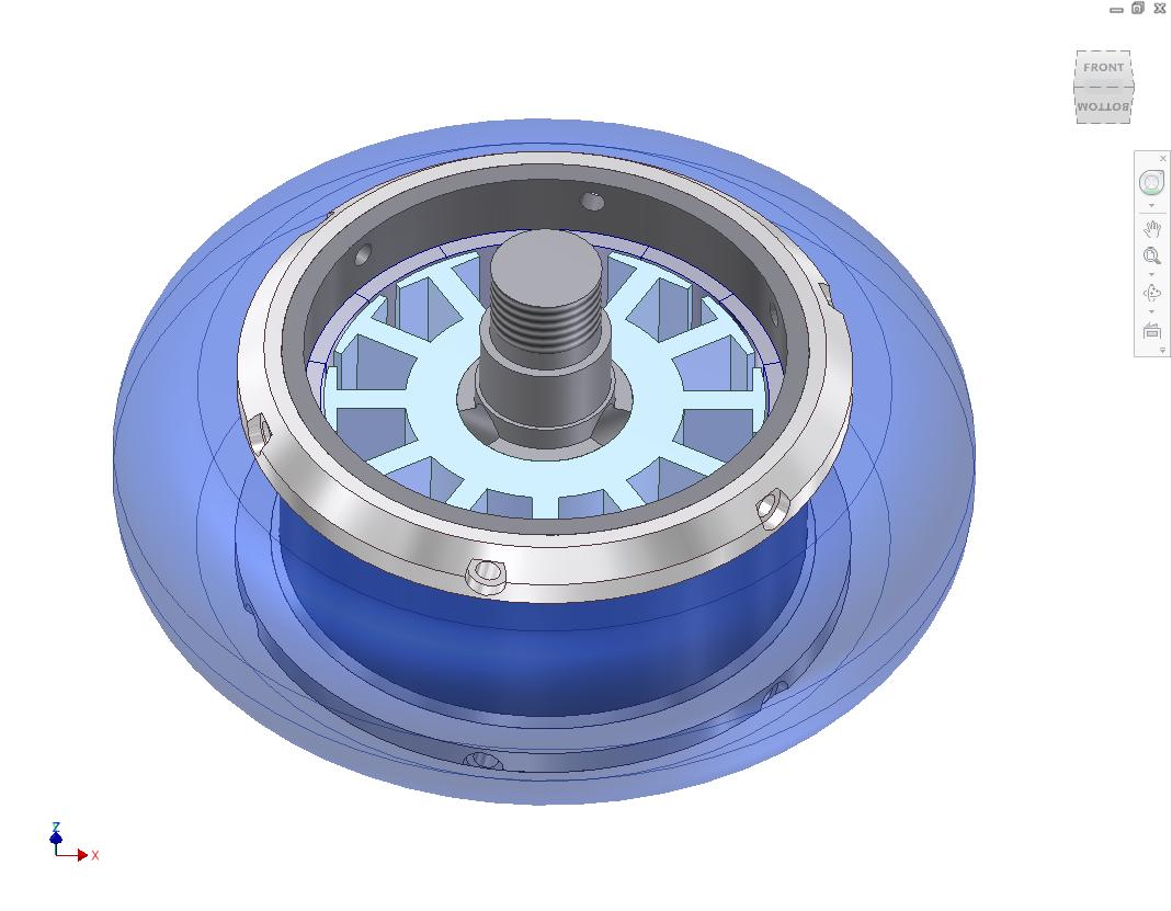
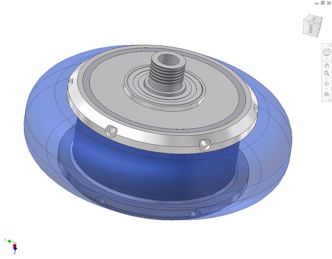
Another view of the motor, mostly assembled. I didn’t fill in any windings for this model, but left enough room in the endcap to account for them.

I elected to redesign the motor using the Compromise Solution I used for RazEr. I save on the part count, but the threading is a bit more difficult to pull off right.  Hopefully now that I’ve done one, I’ll be better at it.

Alright, enough about the motor. I’m satisfied with the motor for now, so I started on frame design. I had stated previously that each Deathblade will probably be two wheeled, as opposed to 4 or more wheels for the average road skate. That’s because I need the central cavity between the wheels for battery and controller volume.

That means I was essentially looking at a box with wheel-mounting flanges sticking out of it, and which has the original Rollerblade boot pattern on top.

Here’s the first-pass result.

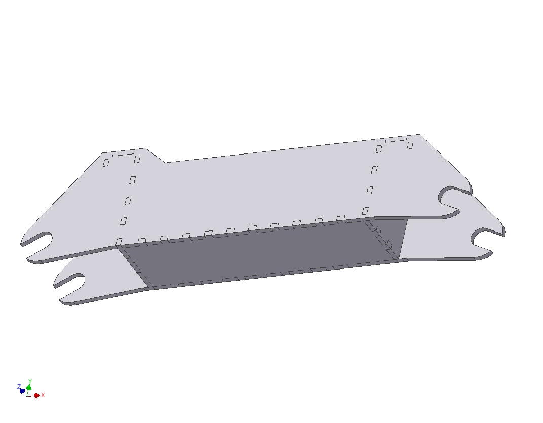
The construction will be similar to Cold Arbor’s frame – slotted and tabbed aluminum plate that do not have additional fasteners. I’ll continue using the weird metallic hot glue method that is neither welding nor soldering.

I guess that makes it brazing? Whatever – Deathblade frames will be one-piece for maximum rigidity and strength.

But wait, how the heck am I going to put things in this one-piece chassis?

Well, for one, it will be open at the top. So it’s really a bucket with wheel mounting flanges and the skate’s bolt pattern on it. The above is a rendering of the whole assembly, which can really be strapped to anything – possibly even your arms or hands if you want to skate while doing a constant handstand.

Or perhaps invent some strange variant of street luging.

I kept the wheelbase the same as the original Rollerblade frame’s because I’ve gotten used to their span. That, and I need enough space to fit batteries inside. The blue prism is a geometric representation of a 4AH, 4 cell lithium polymer battery.

So when’s this thing going to be done? Probably not next week or anything, but I want one power unit built by the end of April.

RazEr: The MITburgring Ostschleife

It’s legit. Yet again!

Of course the first thing I did after making sure the motor worked was throwing it on RazEr. Then, over the past week, I have been beating the crap out of it by commuting everywhere – when I could. The weather has been abhorrent over the weekend.

I’m proud to say that everything has been working flawlessly. The scooter is almost excessively stealthy due to its low profile nature. When fully loaded, the motor makes a very attenuated “brushless whistle” that’s just enough to cause people in front of me to move out of the way instinctively, but they’re not really sure what on earth it is.

Well, until I fly by.

So let’s backtrack and see what happened.

Once again, I start with the finished product. Remounting the motor into the scooter was not a difficult affair, since the center hub and shaft was the same. Otherwise, it just involved hooking up a few wires again. It was nice to see something working after it had been sitting idly on a hook for a year.

Here’s a shot of the business end. Those side rails which form the wheelie bar have been around since the very first wheelmotor iteration!

It turns out that having the motor oriented towards the right side was not exactly a good design choice. I should have installed the can the other way – when torque is applied externally to this orientation, the wheel tries to unscrew the locking ring. This happened a few times in testing, so I ended up Loctiting the ring to the can threads.

Such a reversible process.

Here’s the important parts of the vehicle. If you have never seen this before, there are two 5AH LiPoly packs which form most of the belly volume. The remaining volume up front holds a big model airplane motor controller and a servo tester to convert an analog throttle voltage to R/C signal PWM.

Also, a bunch of LEDs.

Here’s a closeup of the flip side of the motor, the removable faceplate. Technically this should have been on the wire exit side, but it was 5 in the morning when I installed everything and I don’t feel like pulling it apart again.

This was actually the most fun part of the rebuild. I didn’t have another resistive throttle available, because they had all began malfunctioning. The cheapo servo tester I used actually doesn’t take a voltage and turn it into a pulse; it performs a timed discharge of a capacitor through a resistance. This was fine and all when the servo tester was used with the knob it came with, but it meant that I could only use a resistive method of interfacing the throttle. A standard cheap Hall Effect throttle puts out a voltage and won’t let a cap discharge through it.

So I did what any desperate engineer would do – I whipped up a slumthrottle out of some aluminum bits, a potentiometer, and a long extension spring used in torsion. It works better than it should. Using this, I recalibrated the throttle endpoints of the controller and also changed a few settings such as timing and startup.

With this, I went rocketing down the hallway a few times. Because I’m here writing this, you know it worked.

And boy did it work. Here’s the high score of the day, about 1,200 watts on a good launch. I’ve since pulled almost 1,400 by bringing my ‘kick start’ speed closer and closer to the controller’s minimum pickup speed.

The controller, being sensorless and aircraft-optimized, has a minimum speed below which it thinks the motor is stalled and will refuse to start. The “base speed” for Razer is about 5 miles per hour, below which the motor will not actually produce torque when commanded.

And here is RazEr after the “maiden IRL voyage” back at East Campus.

I’ve been using the scooter to commute every change I’ve gotten, just to put as many miles on it as possible. Nothing has yet broken, nor started shaking apart. I’ve been purposefully using sidewalks and cobblestone paved pathways whenever possible just to see what WOULD shake apart first, but the motor and other systems have remained steadfast.

The total mileage on this motor is probably 3 or 4 by now. A single cross campus trip consumes about 0.25 amp hours, and the longest trip so far has consumed 1.3 amp hours.

Here’s a Google map of the most recent “long haul”. I began with a cross campus round trip, then quickly followed with an continuous loop around the eastern half (third?) of campus. The distance was 1.89 miles, so given the 1.3 AH consumption, we can figure that RazEr has a “mileage” of about 25 watt hours per mile.

I’ll try to time a “campus loop” now that the weather is nicer. I’ve monikered the continuous strip of sidewalk and bike path bounded by Massachusetts Avenue, Vassar Street, Main Street, and Ames Street as the “MITburgring Ostschleife”, after the Nurburgring.