It’s been a while since I mentioned LOLrioKart. Not because I haven’t worked on it or anything, but because I’ve been with slammed by everything else in life or just didn’t have the motivation or desire to ever relate anything about it again. You’ll see why.
However, much has happened in terms of kart work in the past month or so. I made and exploded another custom electronic control hack, ran it off a contactor, crashed it, used it to store my mountain of cruft, then pulled it back out to install a new steering gearbox and IGBT half-bridge which has yet to function.
So let’s start at the beginning.
Remember back in the day when I said I would never, ever, ever build another hardware PWM driver?

…Yeah, anyway, let me tell you about this hardware PWM driver I built here.
After investigating a slew of small bike and scooter controllers and discovering that they are in fact very simple creatures, I decided to take a crack at building one myself.
The way most of these things work is through a comparator-based PWM generator circuit. Essentially, half of a dual comparator IC is used to generate a sawtooth or triangle wave. The other half of the comparator…well, compares this time-varying voltage to an input voltage. Whenever the input voltage is higher than this reference wave, the output of the comparator switches states (e.g. outputs +Vcc). When the voltage is lower, it will switch to its normal state.
This is called the intersective method of PWM generation. In this case, the input voltage is provided by the throttle, which is usually potentiometer or magnetic proximity sensor.
Oddly enough, such a circuit is very simple and reliable if all you want is a variable duty cycle PWM output. The difference between this and the last discrete hardware PWM generator I built for the electric scooter project is that the duration and spacing of the pulses didn’t matter as much – for driving a R/C standard input, the length of the pulse carries the information, not the duty cycle.
The output is a normal push-pull arrangement, good for driving power amplifiers.
Of course, if I was going to build my own controller, I couldn’t build a small one. That would be unlike me. I had to go big time.

Luckily, a half-scrapped golf kart controller existed at MITERS. It appears that someone had dismantled it ages ago, but left everything in a sort of Z-state. Some of the power transistors appeared to be fried, which was probably the reason behind the scrapping. Since I had a small bucket of MOSFETs, and the arrangement was very simple, I decided to pull everything off and replace them.

I replaced the existing IRF2807s with my own IRF540s. The current capacity of the 540s are lower, but the maximum voltage is higher. It also has more favorable gate drive characteristics.
Either way, there’s 12 of them. That’s more amps than I care to use.
There’s a TO-220 package dual rectifier every two FETs, acting as freewheeling diodes for electrically-rowdy motors.

Alright, let’s test. I wanted to see how my driver circuitry dealt with the gigantic meta-capacitor that is MOSFET gates. Since I couldn’t put the kart on the workbench, I yanked some equipment down with me.
That’s our smallest oscilloscope. MITERS tends to inherit, scrounge, or otherwise receive for less-than-new value most of it equipment. I swear our other one weighs more than the kart does.

Hmmm, that’s what I want to see, I suppose. PWMing at around 13,000hz (royally overkill) at a 50% duty cycle. The RC characteristic of the switching is pretty clearly visible here. I decided to put a bigger timing capacitor in, reducing the PWM frequency to around 1,500hz, then wrapped it all up and threw it onto the electrical deck.
Naturally, the first thing that happens when I flip the master power switch is a miniature Independence Day fireworks display under my ass. I found pieces of transistor on the ground a foot or two away.
What happened this time? It wasn’t even a bench-to-installation electrical gremlin issue! I literally tested it on the kart!
The best explanation that I and the collective Course 6 minds of several MITERers could come up with was that some of the FETs suffered from gate float as a result of me leaving out a gate resistor that would otherwise have kept them grounded when off. Therefore, if a FET was spuriously, but not fully switched on when I applied power, it would behave as a resistor. With the current dumping ability of the batteries, acting like a resistor isn’t a good thing.
What’s hilarious (and very tragic indeed) about this is that I had such a grounding resistor in the circuit while testing, but somehow it didn’t make it back in while finalizing the wiring.
Regardless, I had one very well baked pseudo-controller.
Sigh.
So what to do now? Simple, put the kart on a contactor.

But Charles, that’s a multipole line switching contactor! It’s not designed for switching high-powered DC motors backed by power sources with instantaneous current output in the hundreds of amps!
Besides, paralleling contactors doesn’t actually gain more switching capability due to the tendency of different contacts to be slightly varied mechanically such that they don’t all close at the same time.
Who cares? At this point, I was sort of convinced that electronics is all black magic. Maybe somehow all the contacts will switch in the same nanosecond. At least if it welded and sent me off uncontrolled into the nearest approaching semi, it would be a glorious way to go.
There aren’t many pictures of what exactly went on, since it was at night and there were no cameras, but to be brief…

That’s a sheared universal joint.

And that’s a competely bent-to-hell steering shaft support.
Long story short, I made the mistake of applying “throttle” in the middle of a turn – the kart wheelied and shot in a direction tangential to the radius of curvature. Remembering geometry class, a path tangement to a curve tends to be a straight line – into a hard curbside.
Luckily, it was at an angle steep enough to not quite roll me over, but enough to wreck almost the entire front end. The force of the impact rammed the steering column upwards and bent the upper steering shaft support. Since I hit tire-first, there was also a torque impulse that exploded the U-joint connecting the two shaft halves.
Also, I twanged up that wheel slightly and bent the half inch bolt being used as a spindle.
Alright, so with no control left to speak of and epic work required to restore it I elected to give up the effort for a while and walk away. Other projects needed attending to, you know, for class. I took the opportunity to clean up the space a bit by piling my crap (which was formerly distributed all over the place) into the kart.

Sad day.
Two and a half weeks pass before a new opportunity arose. Yeah, you probably called it – I couldn’t leave it for long.

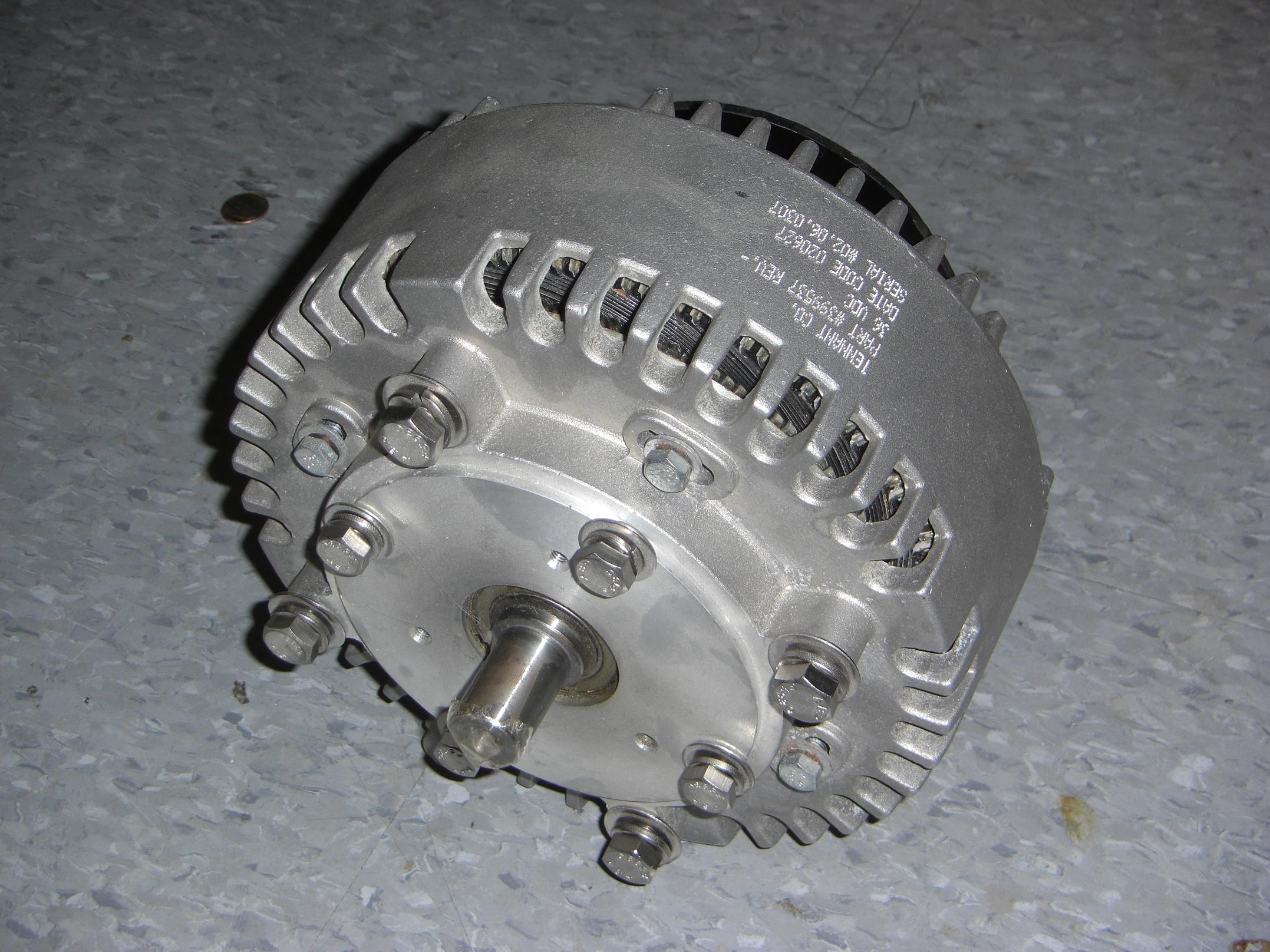
What on earth is THAT? It’s a 100 volt, 200 amp brickFET half-bridge, built by a \m/echanical engineering grad student and 2.007 UA. I’ve been eyeing large power FET/IGBT modules for a while now – always thought they would be better at switching electrically-gifted actuators than a row of TO-220s or cluster of surface mount parts, but I never ponied up the cash to buy a few and test them.
Besides, if I did, I probably would have blown them up before actually getting to the kart.
Now I need a kart to mount this thing to.

Taking everything off that needs to be unbent or remade.

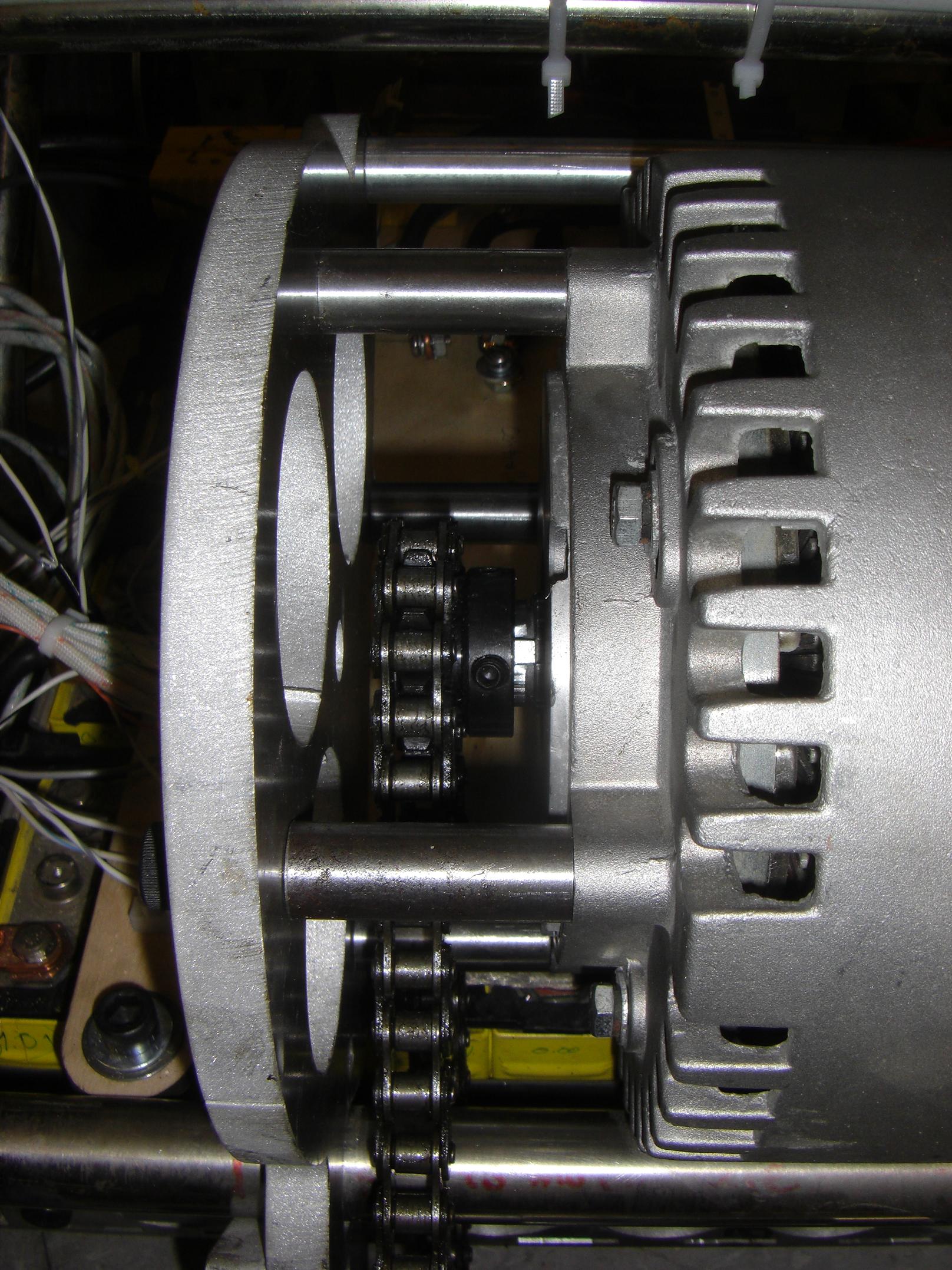
Bevel gears, left over from another project.
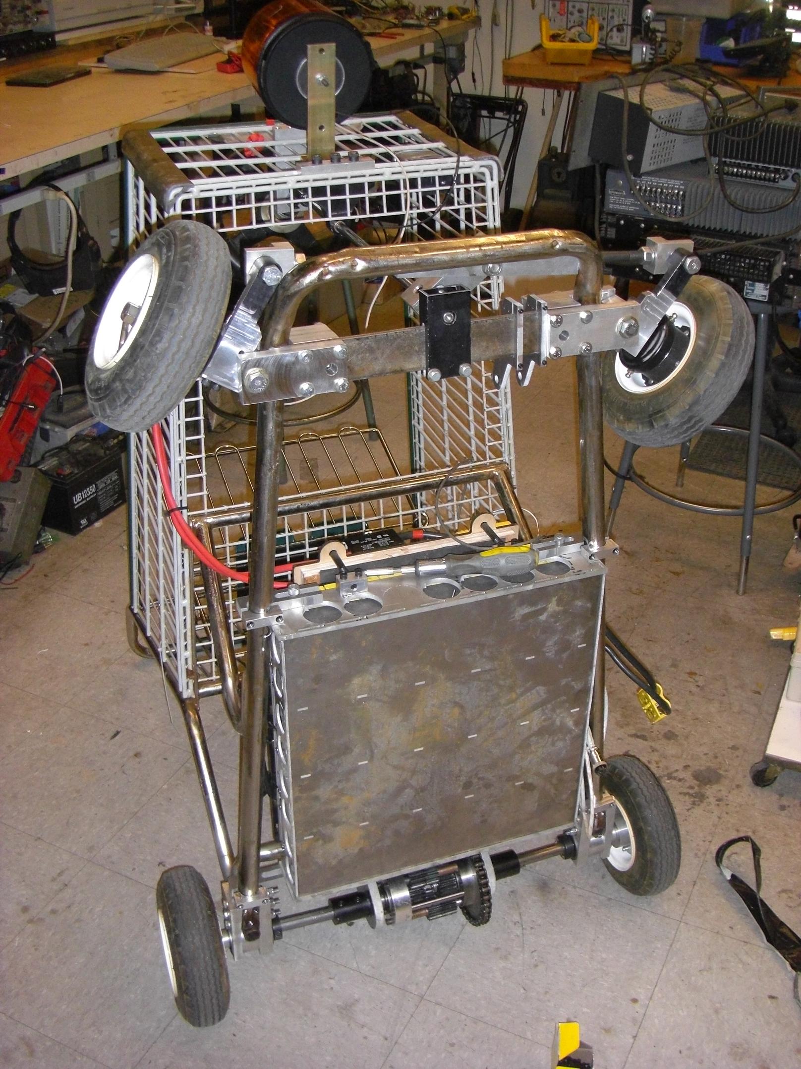
I toiled for a little while over exactly what I should do for the new steering column. I did not want a horizontal steering wheel. The physical form factor of the kart – it’s substantially taller than most go-karts – precluded a direct link to the steering linkage while keeping the steering wheel at a reasonable angle.
Solution? Make the steering wheel axis horizontal. This much more closely approximates the layout of most passenger vehicles. The differerence is that I would still have a vertical shaft, but the wheel would be connected using a set of bevel gears.
The other upside to this is that I gain an actual steering ratio – no more 1:1 through a U-joint with a mile of backlash!

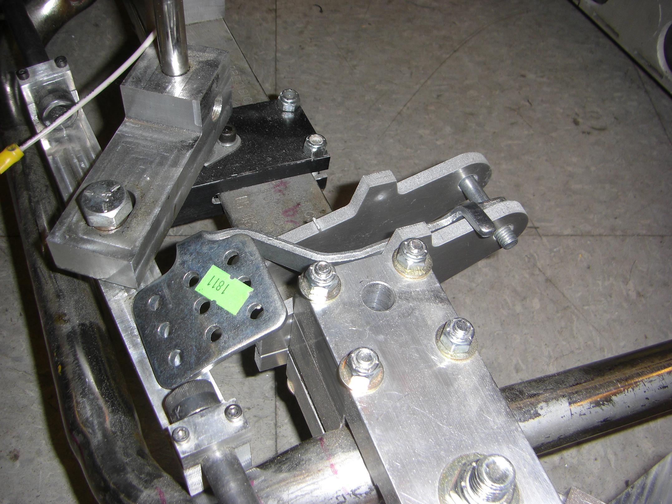
Stiffening up the whole show with another found giant aluminum trunion thing. The bevel gearbox will mount on top of the new topmost bearing block.

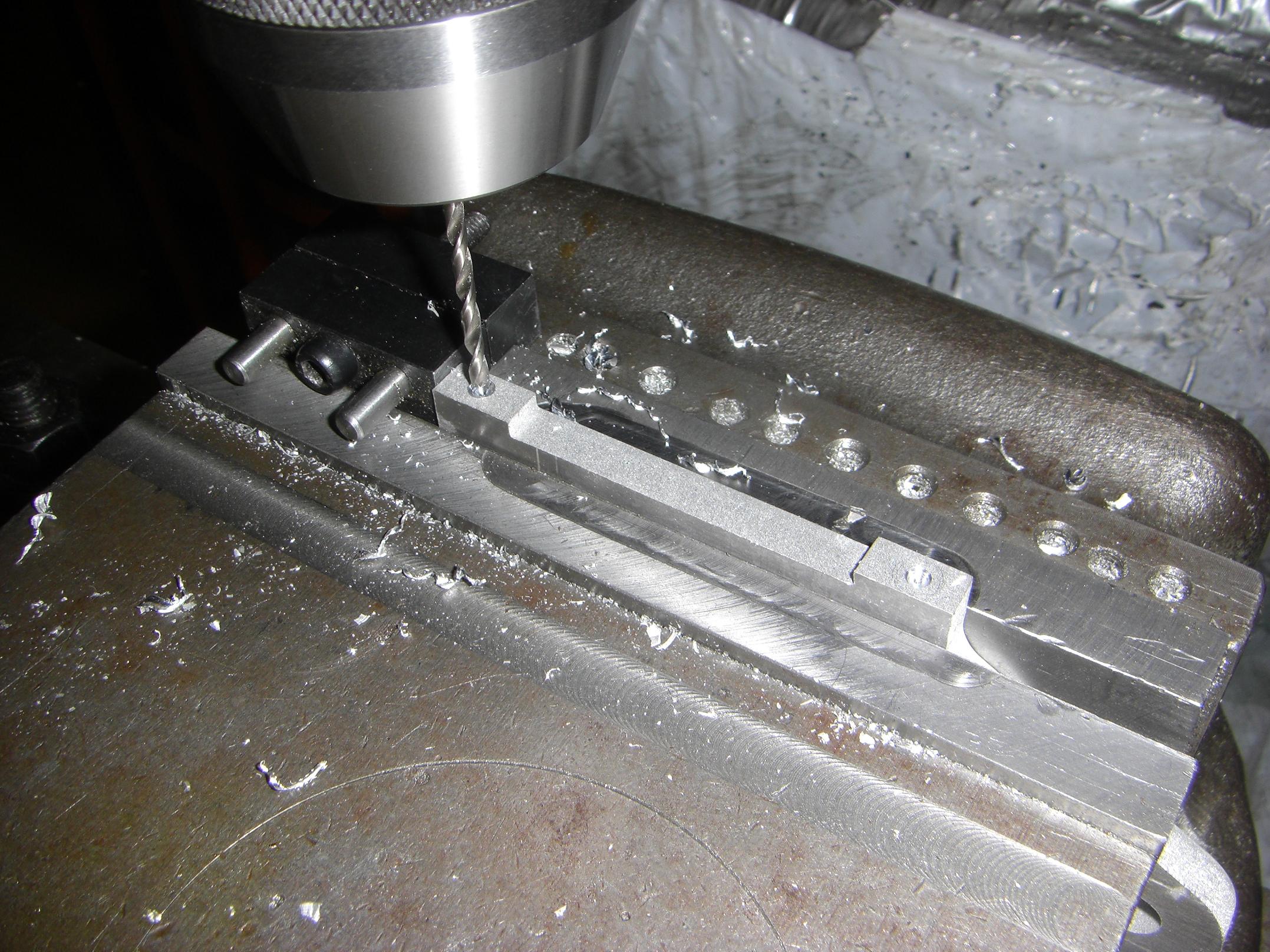
Gearbox mount holes drilled into the top bearing block.
But wait, there’s more. A giant steel standoff now connects both blocks. Retained on each end by a 3/8″ cap screw two inches deep, this assembly is going to be stiff. I intend to add shaft collars galore to this such that the front end of the basket has some semblance of structural integrity.
Next, to mod up the gears.
 A problem.
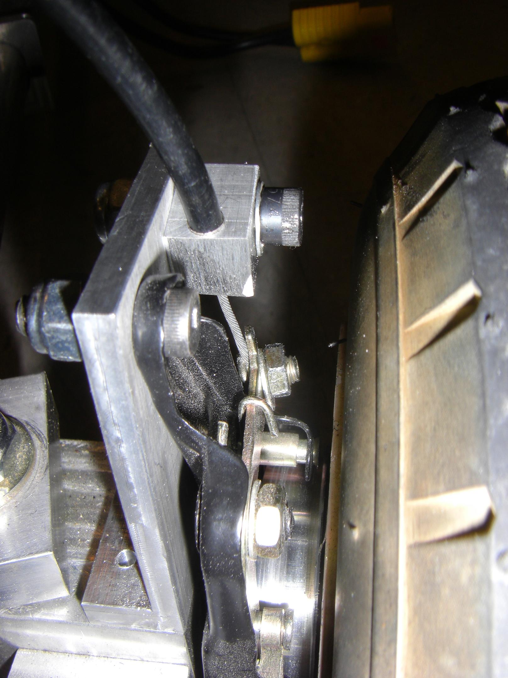
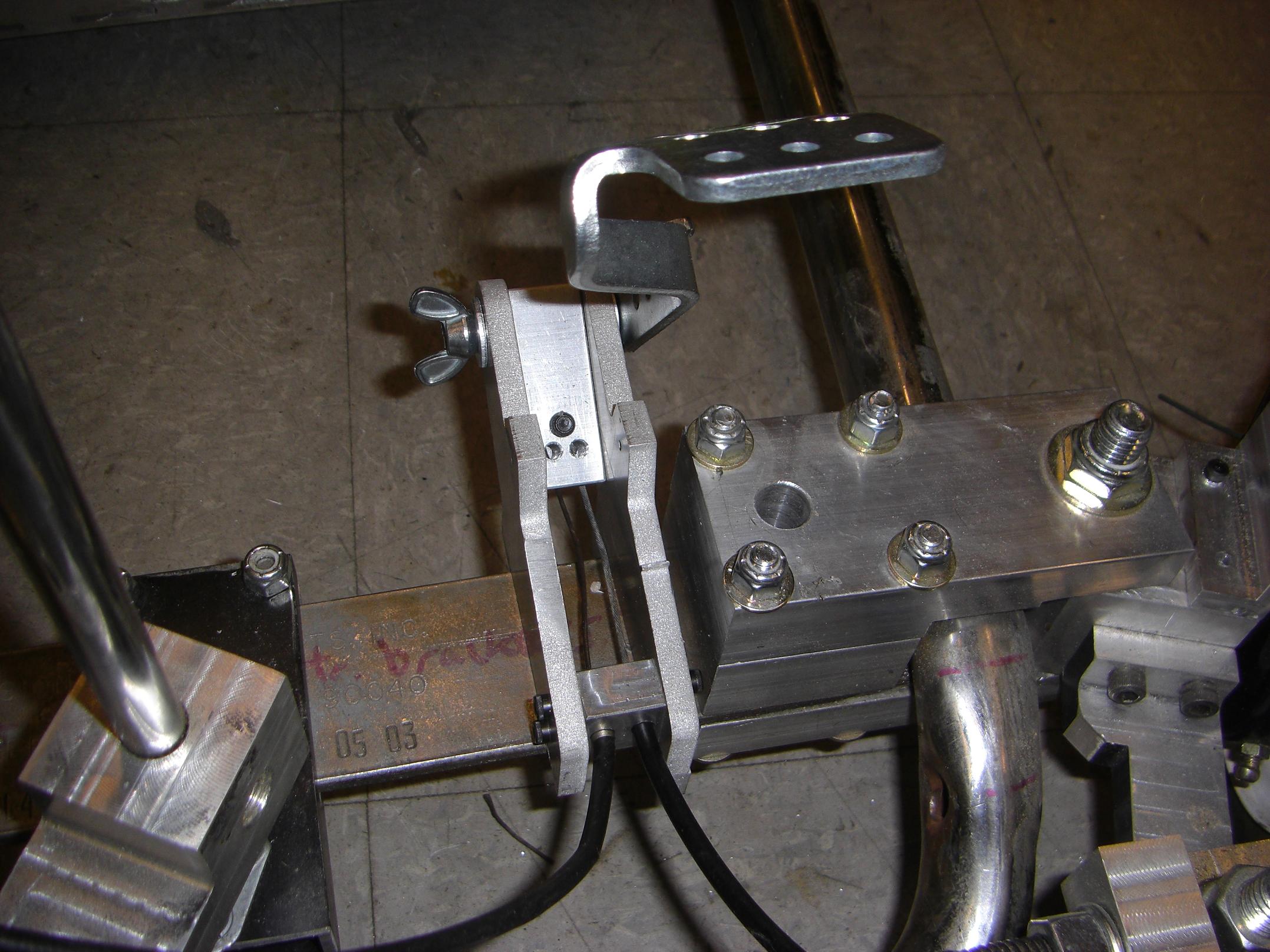
While assuming Ghettopost in the boring position, the socket head cap screw that opens and closes the post clamp sheared off. I guess it didn’t like repetitive cycled loading.
I needed a fast workaround that didn’t involve remachining that part of the tool holder. What else can close a clamp around a shaft? Another clamp. It worked spelendidly.
(Reason #67,293 I’d get thrown out of a real machine shop)

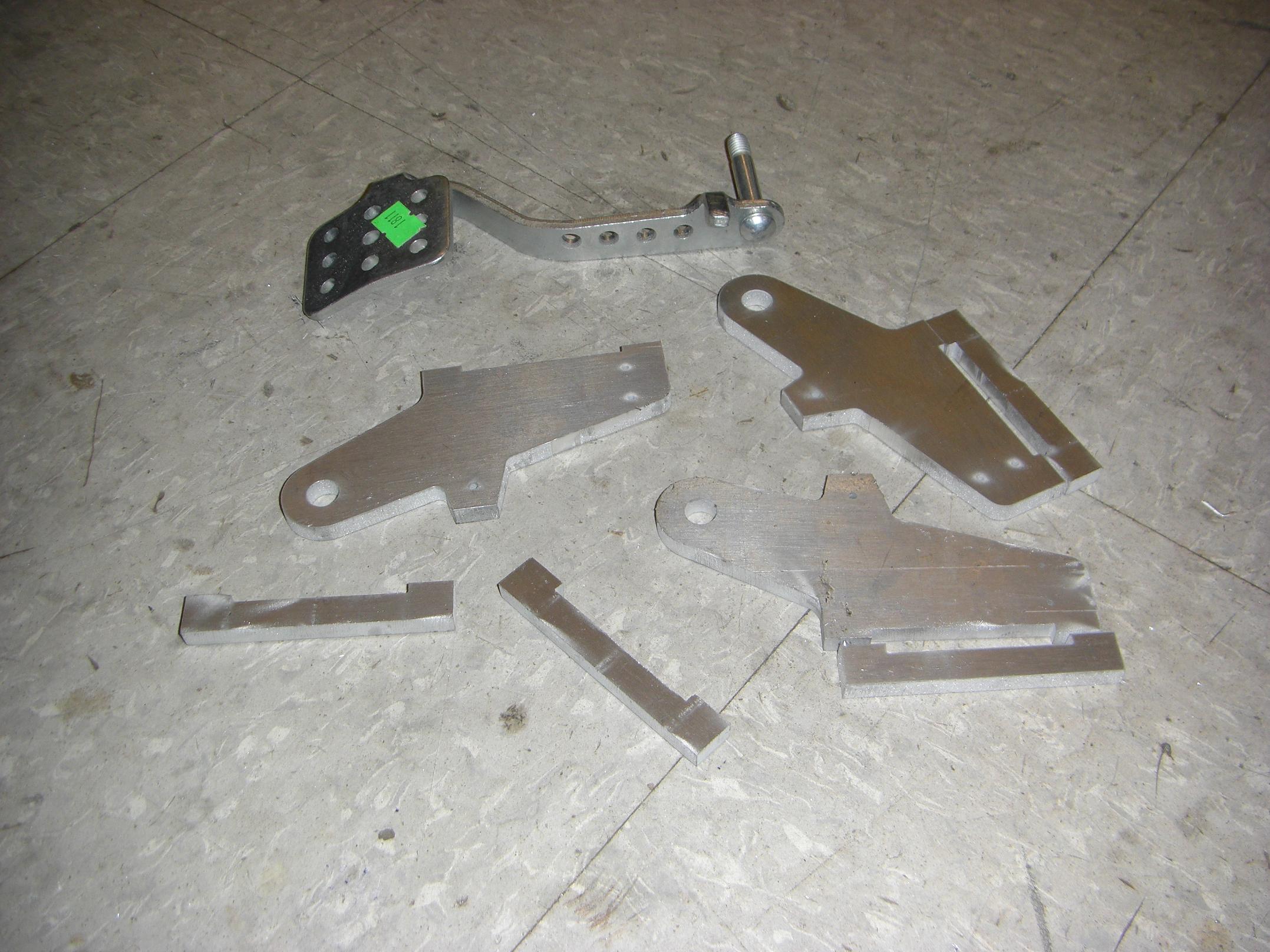
Scribbling the part you want to make on the stock you’re making it from – a classic tactic of mine.

Carving out a hole that is big enough to pass the larger bevel gear into the gearbox stock, a 3″ square aluminum tube. The layout for the gearbox is slightly odd – the bevel gear is retained by the top bearing block, and the gearbox with pinion attaches to said bearing block. The two gears are not in an integral assembly.
I decided to make it this way since then I had some marginal ability to adjust the amount of backlash in the teeth – just shift the gearbox around.

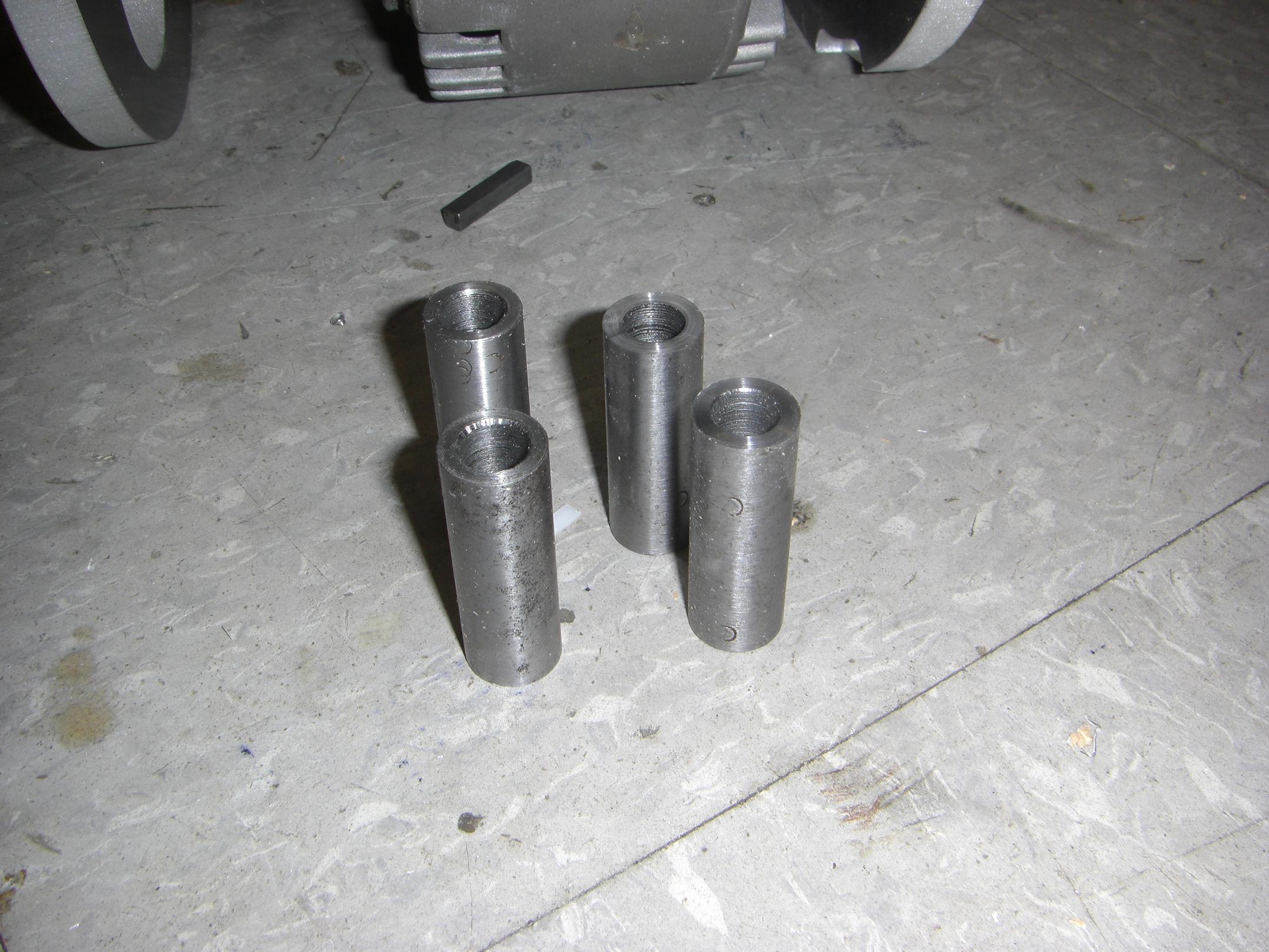
Gears on their shafts. Like everything else on LOLrioKart, they are retained by ginormous set screws.
Set screws only work under two circumstances – if they have a pre-drilled hole to sit in, or if they’re enormous for the task at hand.

Endcaps for the gearbox. Again, I choose my usual tactic of on-the-fly manufacturying – carving things from giant blocks of aluminum by brute force.

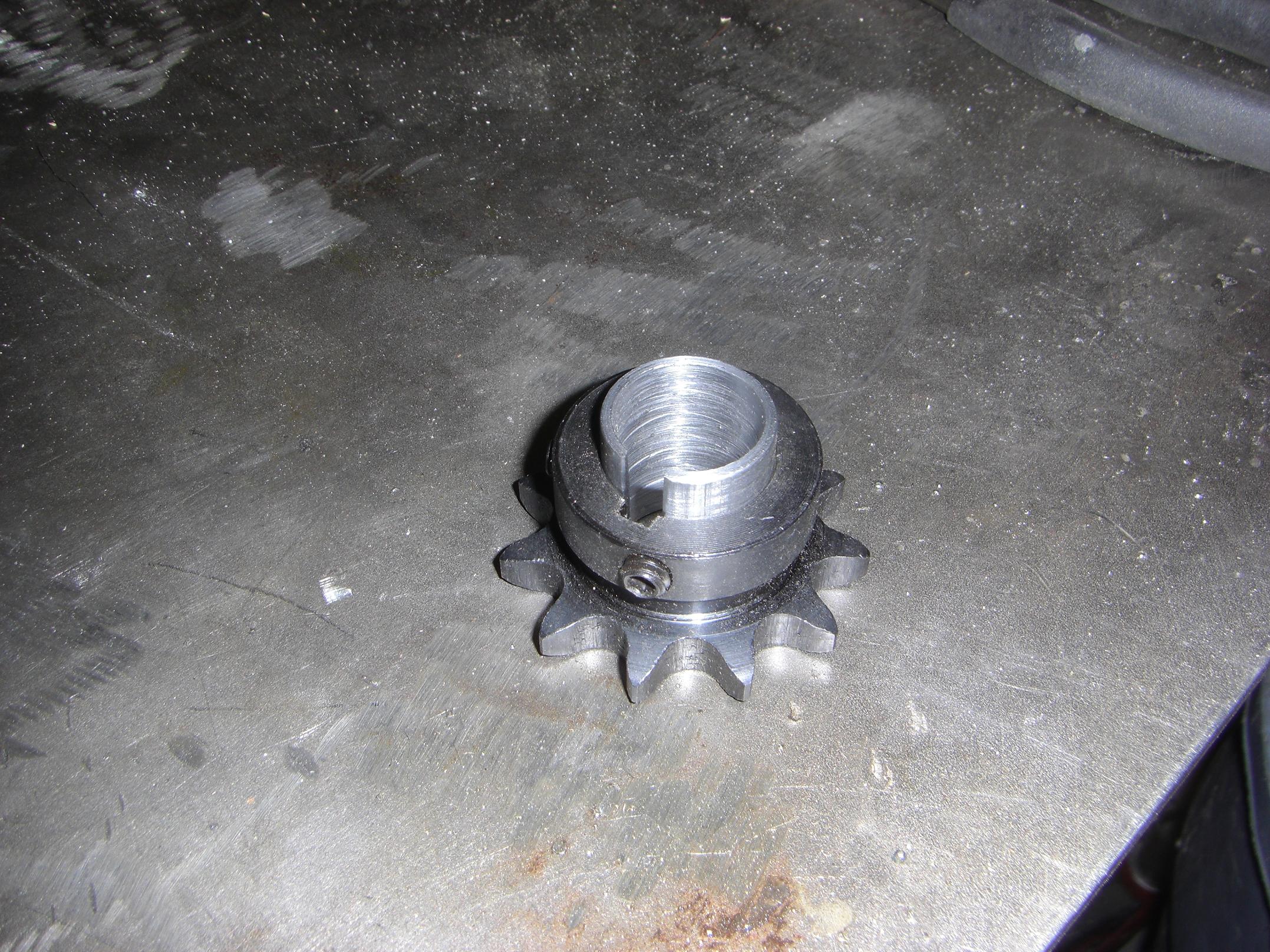
Pinion gear on the steering input shaft. Since I hate retaining rings, I naturally chose to keep everything together axially with a large retaining ring.

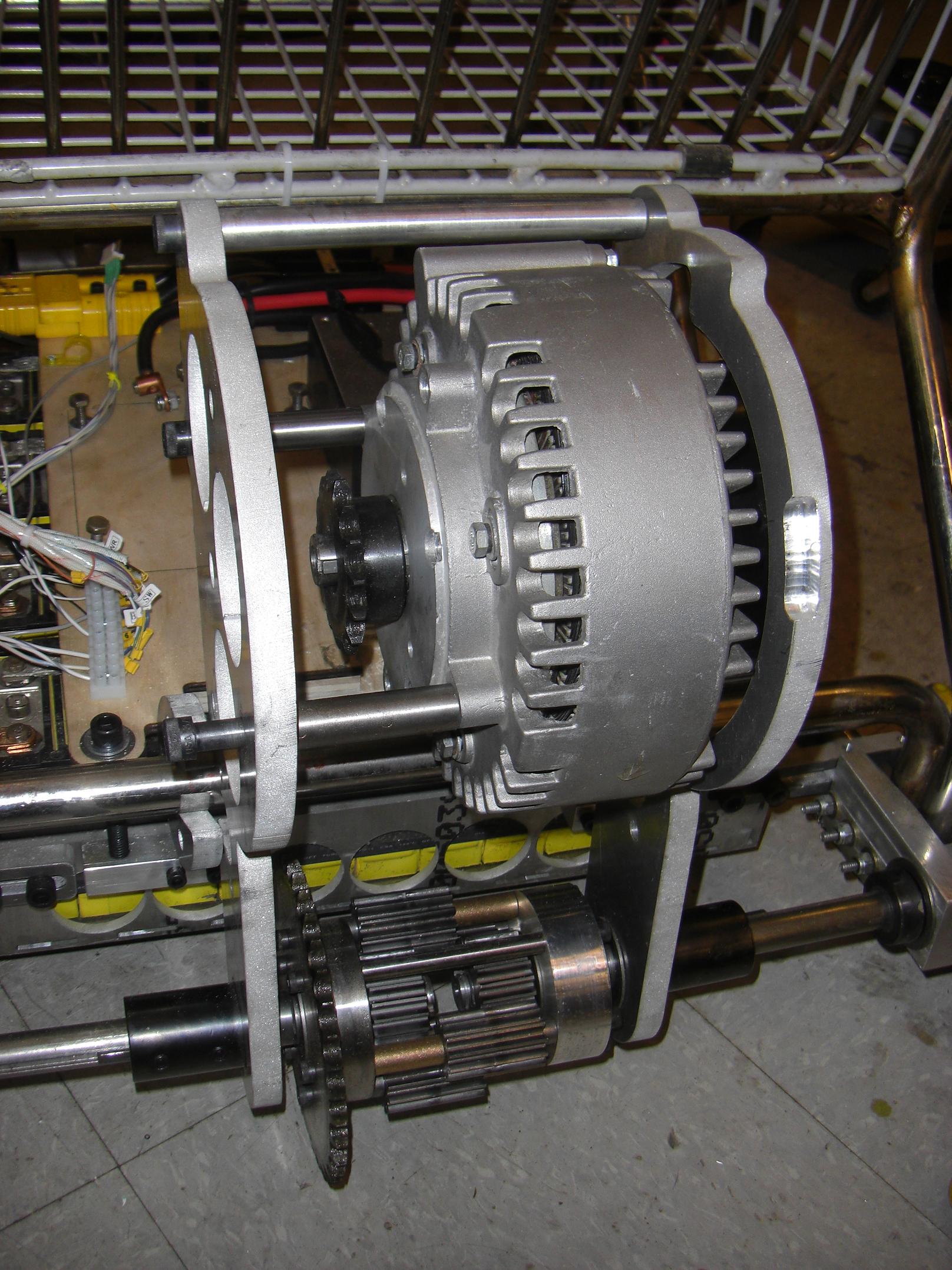
The gearbox is installed. The steering wheel pops on and off of the hex shaft (It’s a quick-release, legitimate racing type).

Proper gear mesh is a good thing.

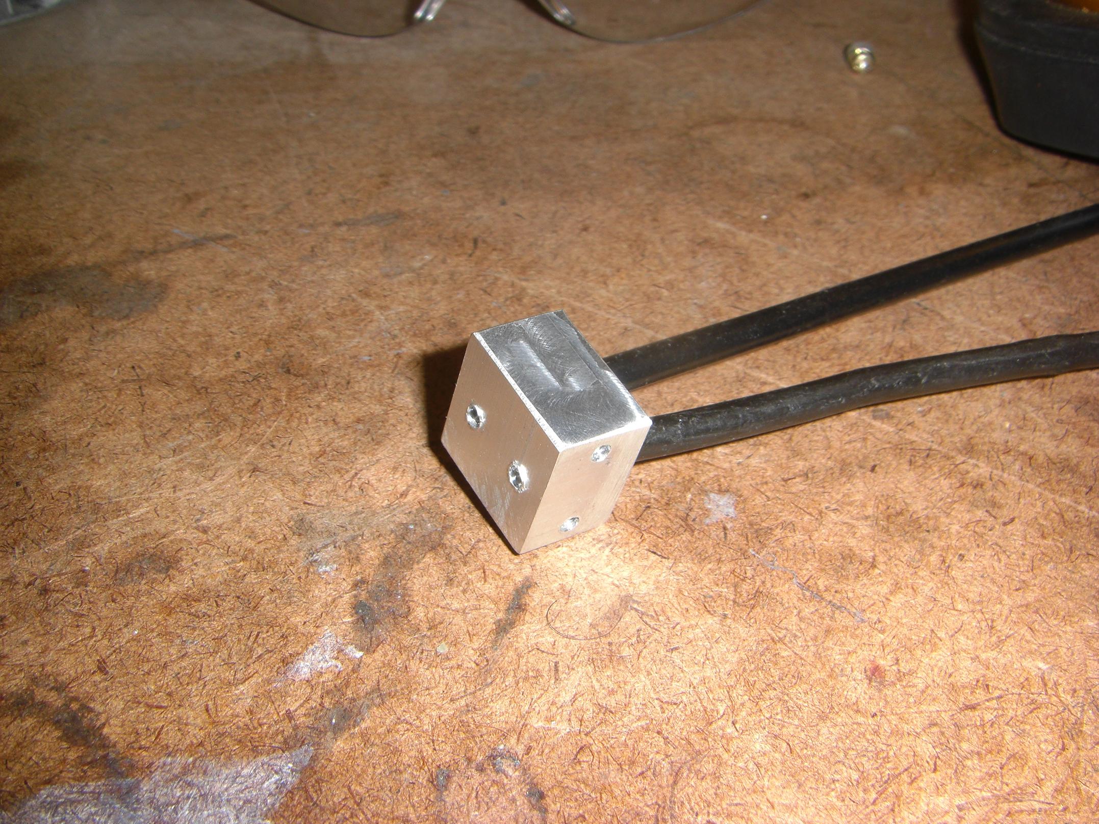
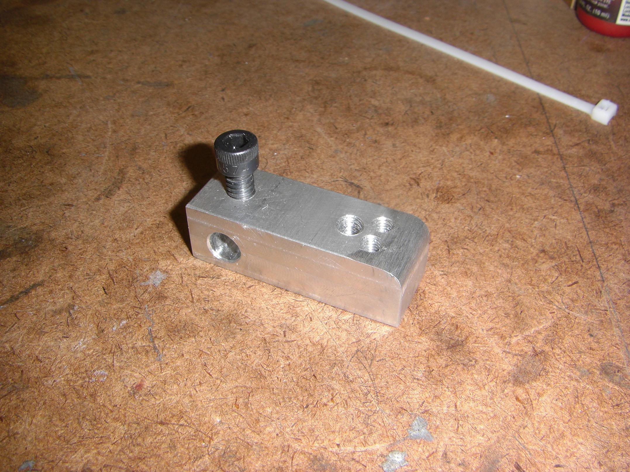
To finish things out, I needed to join the shaft that connects to the steering linkage itself with the one coming out of the gearbox. Since it was 2am and McMaster was closed, I whipped up a quick giant shaft coupler, two piece clamp type, out of some 1″ steel.

And the final product.
Hey, I have 180 degrees of steering travel now! And essentially no backlash to speak of. The only source of it now seems to be between the steering wheel itself and the hex bore – probably because the wheel is metric and the hex shaft is antimetric.

Uh oh, here we go….

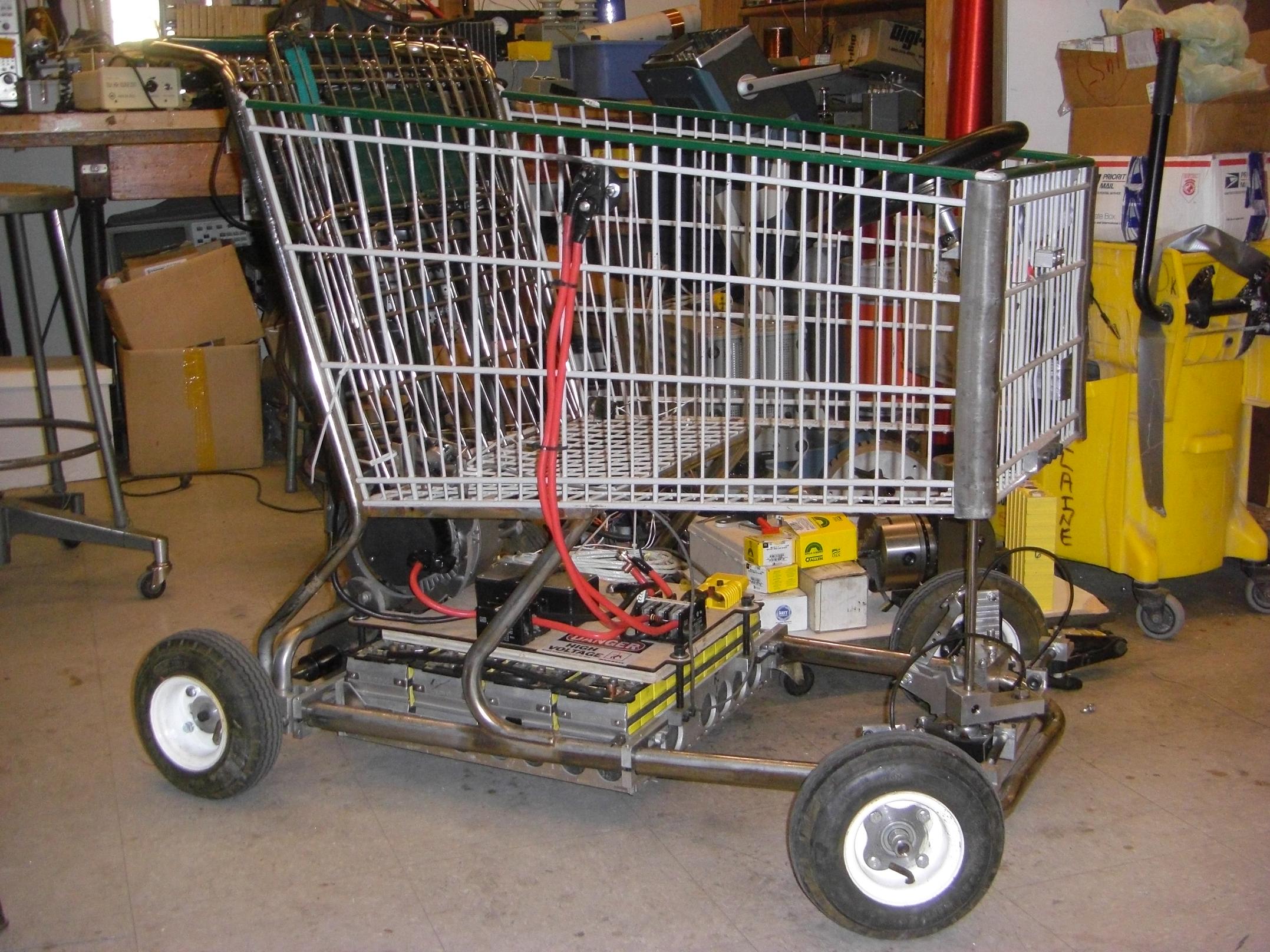
All wired up, with my previous gate driver device (beefed up and properly grounded!)
This thing worked just fine on the bench with a smaller motor, so it ought to work now, right?
Besides experience having shown otherwise, I decided to run some continuity and voltage checks on the entire system using a meter.
This is when I discovered that the kart frame is live. It measured exactly 42 volts everywhere.
Bad?
Out of precaution and a desire to keep my own sanity, I elected to not hook up the battery and turn it on.
Ah, electrical engineering black magic. Last time I had frame continuity issues, it was grounded. Now, weeks later, without touching anything, it switches polarities?
Either way, this entails a full teardown of the electrical system. I should probably check the insulation on the batteries – while they have nitrile rubber sheets all around them, I might have missed a spot. A metal mounting screw may be sticking out too far. Something.
Stay tuned for moar!