LOLriokart update 9: Meet the Flintstones Edition

It steers.

The differential was a short distraction project before I left for Atlanta.  I didn’t *really* need it, but it was a neat thought experiment that would contribute to the vehicle if I had it. What’s more essential to the vehicle’s handling is the steering system, which I’ve sort of halfheartedly been working on for the past while.

So over the last few days, I summoned the effort to finish said steering system. Another pound and a half of aluminum billet later…

i accidentally the hallway, but the steering linkages work.

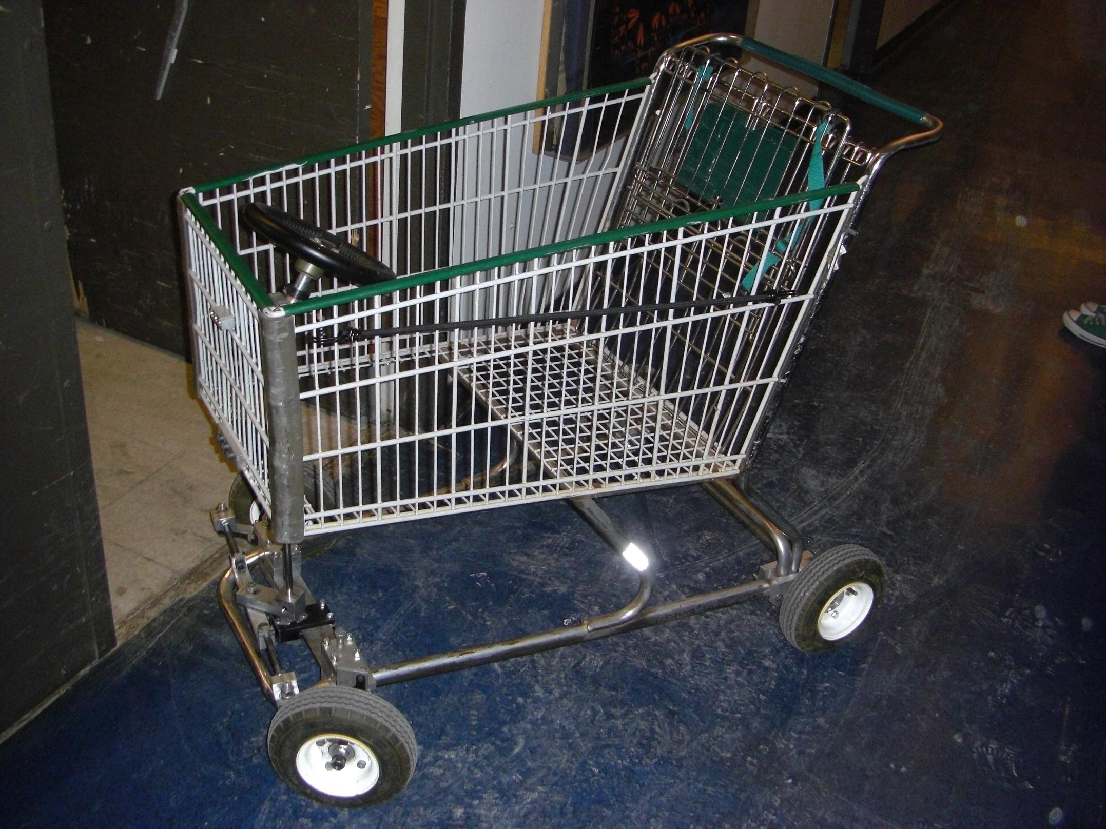
It works! Because now the driver has a controllable degree of freedom, everyone in MITERS at the time took turns pushing/being pushed through the hallways. LOLrioKart is a big hit, even before it moves under its own power…

So here’s how it was done.

Steering connecting link

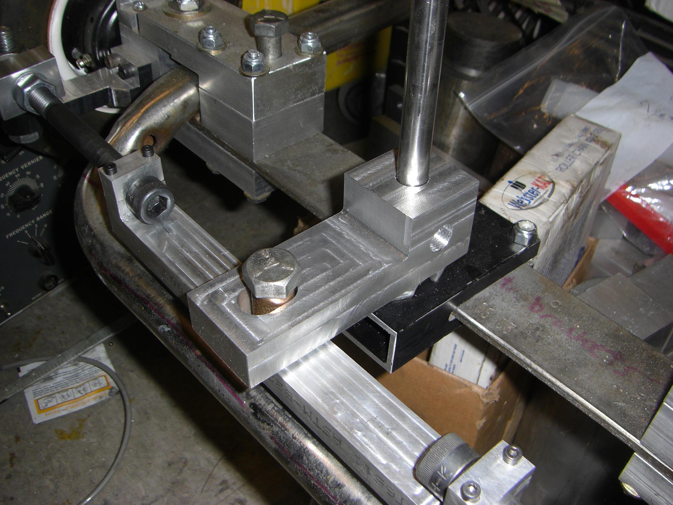
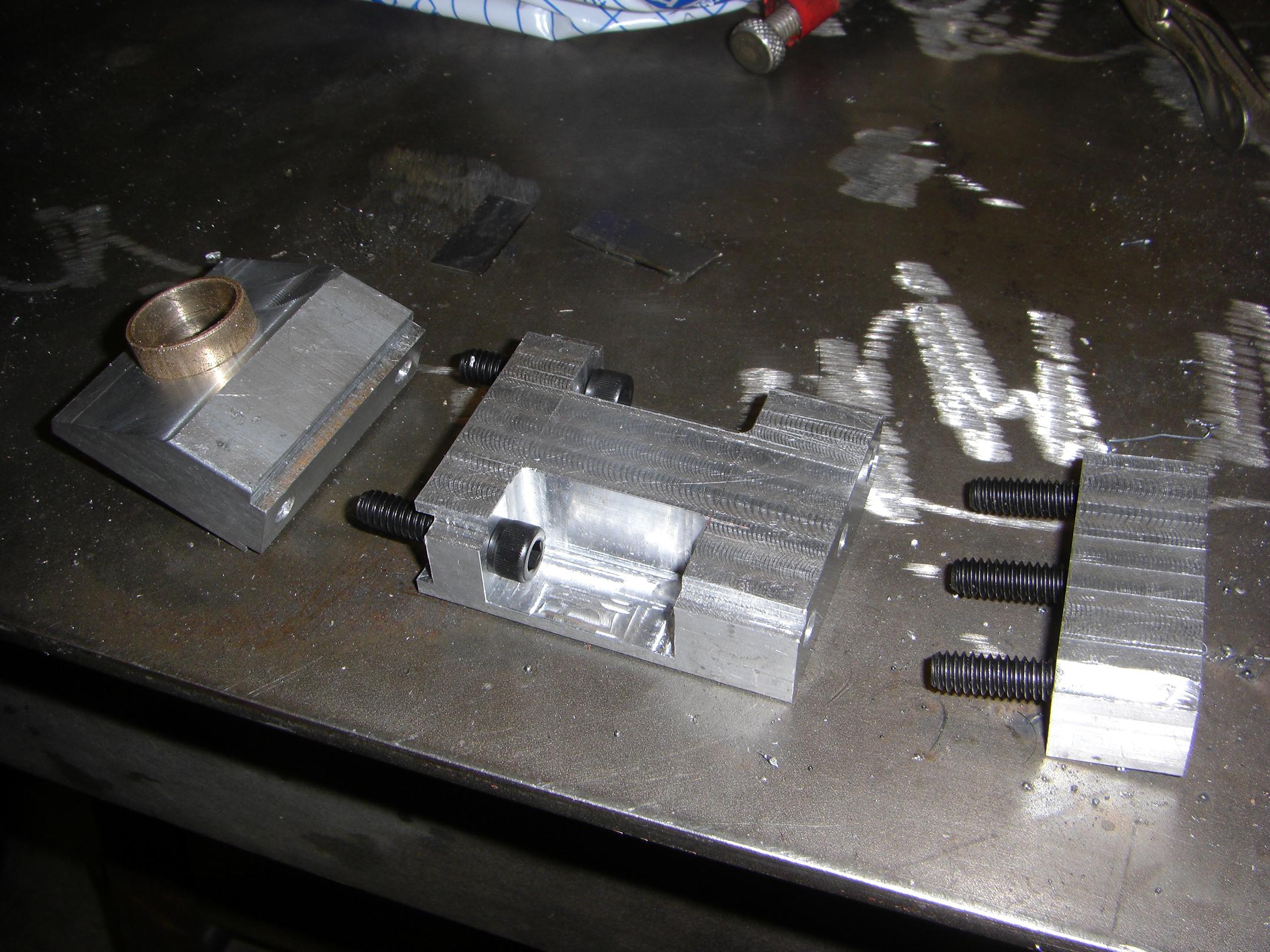
MORE BILLET! Here, the cap screw linkages have been joined. This 10″ long, half inch thick span of aluminum holds the cap screw heads in clamps at the ends, and has provisions for the Pitman link pivot pin in the middle.  The cap screw sit in semicircular cutouts made by a ball-ended mill. To lock the linkages where they are, the clamps are tightened down. If I ever need to adjust the toe angle, I can loosen the clamps, turn the cap screws in or out slightly, then relock the clamp.

Pitman arm and steering pin slide joint

One more big chunk of aluminum comprises the Pitman link itself. Notice that the pin actually travels in a slot. This is because the pivot point of the Pitman link is slightly in front of the pivot point of the wheel kingpins. Each side of this contraption is its own unequal-length 4-bar linkage. Unfortunately, I can’t have a rigid front connecting link if this is the case.

So to work around it, what would normally be a pin joint  is actually a slot. This means the steering response is nonlinear, but as the wheels can only turn around 90 degrees total, the nonlinearity is small enough to be neglected. I’m not going to care about a few degrees true deviation from a linear response when I’m flying across potholes at an unhealthy speed.

Monster billet.

Completed bottom half of the steering system. That’s alot of shiny metal.

Some of my friends have expressed concern over the unhealthy amount of aluminum billet on LOLrioKart. This is often followed by giggly gossip along the lines of “He doesn’t know how to weld!”.

MITERS has a MIG welder that I have used on occasion, such as when a big crack opened up in one of the frame tubes on my bike. I don’t like welding for something like this – while it would be simpler, faster, and at this point lighter, it is just too permanent for a project whose design parameters change on a whim. It would also necessitate grinding off the chrome finish on the tube frame and adding dark, amorphous blobs of metal in its place. If I decided I didn’t like how something finished, dismounting it involves an angle grinder. Yes, I could have machined form-fitting steel pieces and welded them accordingly, but then why bother with the welding?

Aluminum goes fast on the machines anyway, and I think the disproportionately large blocks of shiny metal just give it a more unique appearance than the average tube-and-plate framed go-kart. If I had as regular access to CNC machinery, then the pieces would be significantly less blocky. For now, I’m more concerned with the functionality – I can add “features” later.

tl;dr weldin sux

Alright, the lower half is done. To the upper half!

Milling an aluminum section to a 30 degree slope

Here’s the first of 3 parts to the upper steering wheel mounting system.

To avoid having “municipal bus syndrome“, I purchased a small universal joint and aimed to mount the steering wheel at an angle no less than 30 degrees from the vertical. Fortunately for me, the universal joint only seems to operate to that point anyway.

Either way, I needed to make the angled shaft support. We don’t have an angle vise, so I had to tilt the head on the Bridgeport. I hate doing this, since returning the head to dead vertical is a painful procedure involving jiggling a dial indicator. Usually I just eyeball it – works fine as long as I’m not taking massively wide facing cuts.

Bushings from Uberclocker's fork pivot find a new life...

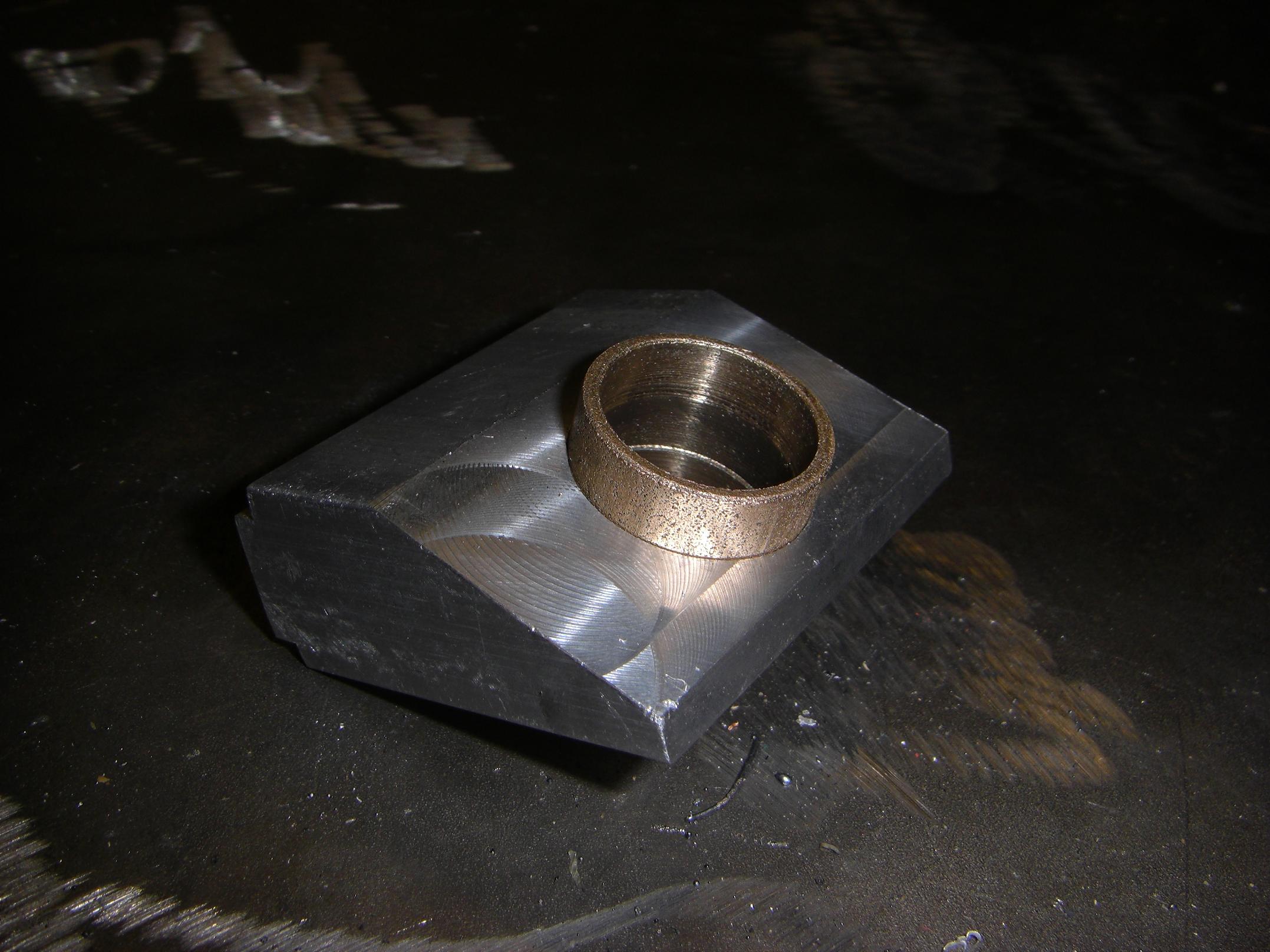
The finished part. This holds the steering column at 30 degrees. Two back-toback 3/4″ bore bushings, from Überclocker’s arm pivot before I switched to ball bearings, will support the steering column. Along with the 1″ wide bushing of the middle support and the 5/8″ self-aligning bushing on bottom half, I think I’m all set for proper shaft support.

The center spacing block of the upper steering column support.

Here’s the second of three parts. This bridges the empty space between the angled shaft support and the front of the kart basket.

By this time, I had run out of 2″ x 1″ rectangular barstock. So I had to rummage through our stuff bins in order to come up with the half-processed stock for this piece. No, the crude milling marks on top are not mine, or the litttle stairstep at the edge.

You’ll see how it all goes together shortly.

All 3 upper support parts

And the third part is done. Now it should be making more sense.

The third part just sandwiches the kart’s wire frame between it and the spacing block.

Now let’s hook up the steering wheel to all this shafting.

3/4" bolt makes a quick 3/4" axle in a pinch

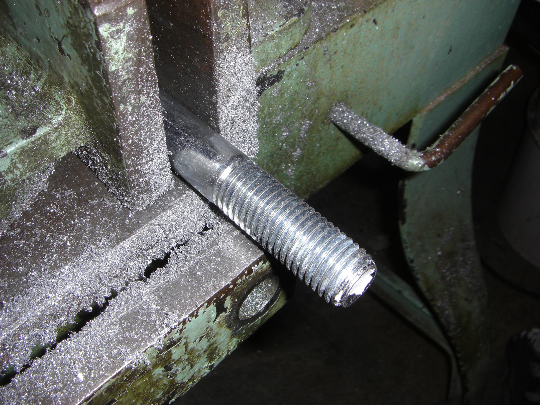
I needed more 3/4″ shafting. Unfortunately, I used all of it for the rear axle and differential. Not wanting to dispose of the solid axle before I knew whether or not I was going to use it in the end, I stole a big 3/4″ bolt from the hardware bin and called it good. A trip to the bandsaw removed the threaded end and the head, leaving me with the meaty steel middle.

1" hex stock to mate with the steering wheel

Next, I made the steering wheel adaptor. The steering wheel is a quick-release type for legitimate race karts. It has a 1″ hexagonal bore, in which sit 3 balls protruding through the vertices. A spring-loaded collar keeps the balls in that position, until it is pressed, upon which the balls are free to fall outwards a bit. Normally, these balls would be shoved into a groove cut into the steering column, so that if the collar isn’t pressed, the wheel is tightly retained on the column, but can be quickly removed simply by pressing the collar and yanking.

Luckily, I had a piece of 1″ hexagonal steel stock. The bore is a squish-fit (better than a press-fit!) for the 3/4″ boltshaft.

Upper steering shaft grooved and turned

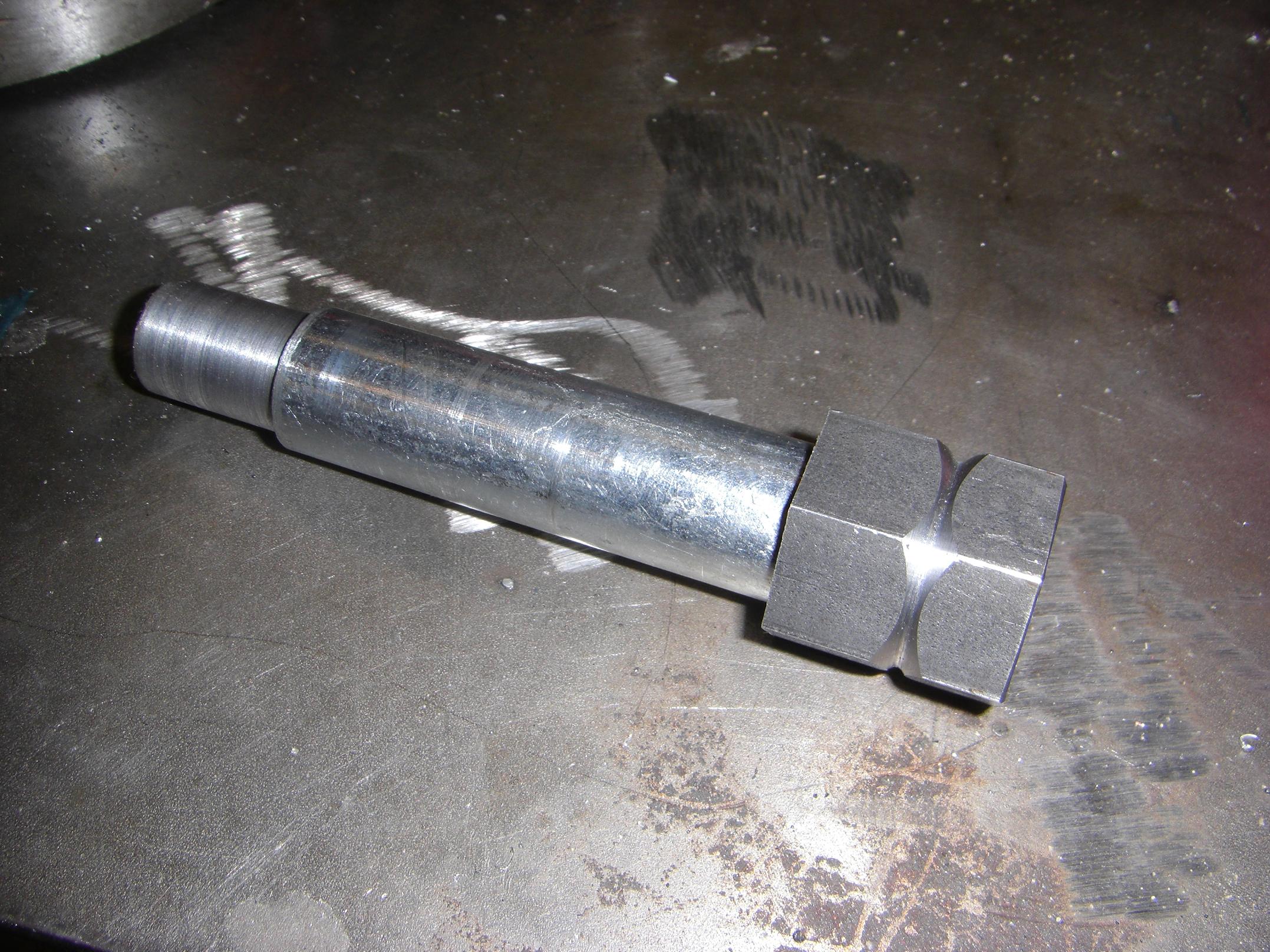
Here is the hex end grooved, and the other end of the bolt turned down to fit the 5/8″ bore of the universal joint. The hex stock was squish-fitted with a 5-ton arbor press.

The upper steering shaft assembled

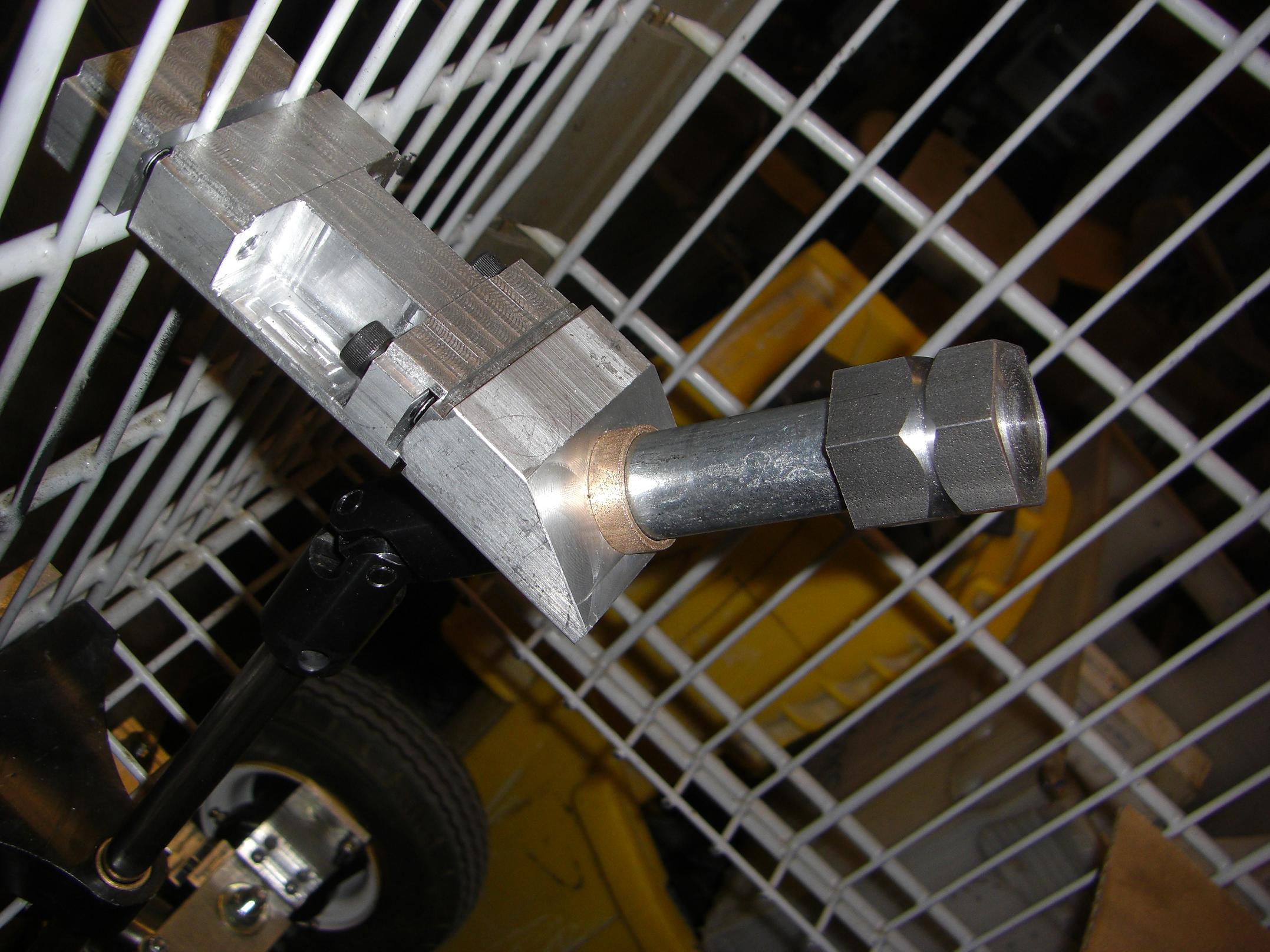
So this is how it all goes together. When the three cap screws of the shaft support are tightened, the whole assembly is rock-solid. Notice the tongue-and-goove setup on the bushing block. This was to allow for the possibility of misalignment from my eyeballing. I could insert little shims in the gap to adjust the slack this way.

Incidentally, this is the 100th LOLrioKart build pic.

Now to connect the two sides together by pinning the shafts to the universal joint.

The wrong way to fixture a bushing.

The lower shaft is 1/2″ in diameter and the universal joint takes 5/8″. The solution was a reducer bushing. Simple, but how to drill a hole in the same place in both? Optimally you’d have designed the parts beforehand to fit together.

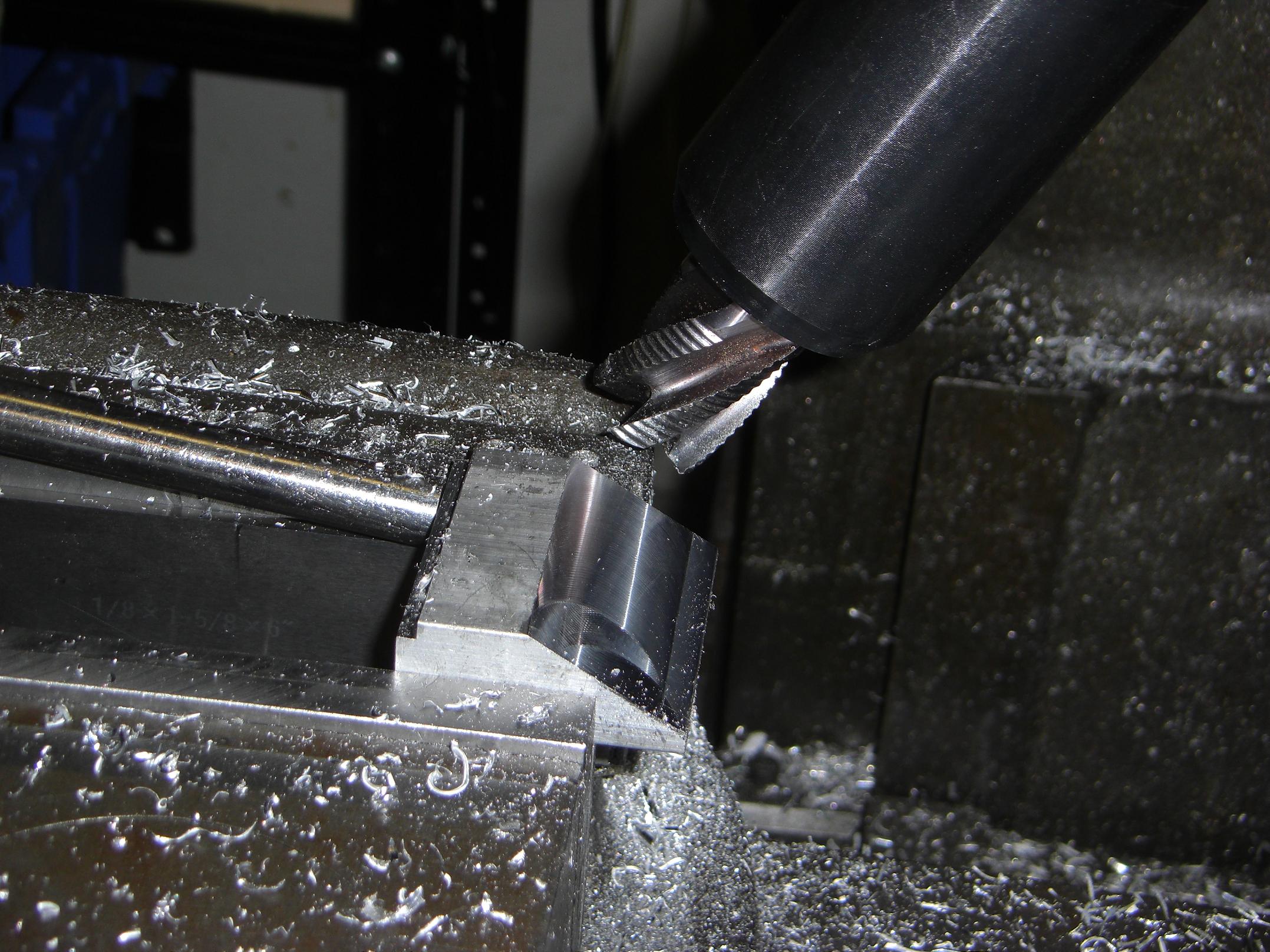
This is how to not do it, but it worked in a pinch. I violently clamped the bushing against the shaft and stabbed a carbide 1/4″ endmill through both.

Opposite flats in the lower steering shaft to align the Pitman arm

While I had a good endmill in the mill and the steering shaft right there, I added some Flats of Set Screw Gripping (+1?). This, along with the pinned universal joint connections and the hex bore of the steering wheel, makes sure there is a fixed angular relationship between said steering wheel and the front wheels.

Steering assembly...well, assembled.

Everything put together. I couldn’t find a real pin for the universal joint, so I made do with a random standoff and a random 1/4″-20 cap screw.

On the ground, with the steering wheel.

And the steering wheel is mounted! After a check of all the set screws, it was time to rock the hallways Flintstones style.

Post-test run LOLrioKart in the N52 hallway.

I am proud to announce that, even with our reckless disregard for health and safety, the death toll from this initial human-powered run was 0.

Although there WAS a close call with someone’s dog jumping in front of the kart, necessitating a near ass-dragging emergency stop from me.

LOLriokart Update 8: Did I mean later? I mean now.

From

to

in 13 hours. There was much Mountain Dew involved.

I got the gears, shafts, and bearings in Friday afternoon, to my surprise, as the mail desk folk usually take off early. At first, I wanted to leave it as an exercise in Atlanta. Take the last weekend off to relax, etc.

Then I came to my senses. Building IS relaxing, after all, so I crossed the Antarctic continent to MITERS, where I spent the next day watching piles, both of snow and of metal chips, grow in height.

So let’s begin.

Here’s the raw materials rundown on Saturday at 7AM. Two 21 tooth, 12 pitch spur gears. Some lengths of precision-ground 3/8″ shafting. A handful of bushings. Four large bearings. Spur-gear-on-a-stick (pinion rod). The 3/4″ shafting and large sprocket came from the parts bin.

First order of business was roughly machining all the raw parts to final dimensions. Since roughing and finishing operations require different tools and attention spans, I figured it was better to do this now than repeat the process for each part.

Cutting the hubs off the spur gears.

Yes, I know I’m supposed to use a collet chuck for these things to avoid grunging the teeth, but I found that the tips of the chuck jaws fit between two gear teeth nicely. This positive mechanical contact meant I could shove a little harder on the parting tool and have nothing blow up.

I needed 6 little shafts. To cut them one-by-one would have been unnecessarily repetitive, so I stacked the raw shaft stock on the horizontal bandsaw and clamped them down with a block of wood. Without the wood,  at least one shaft would not clamp properly due to a variety of misalignments and tolerances. This way, I could cut 3 at once.

I wasn’t as lucky when cutting the spur gear rod into smaller chunks, since I only had one spur gear rod.

It’s giant sprocket time. The outside jaws for the chuck are worn pretty heavily, so it’s a bit of a trick actually getting something to run true, especially at large diameters, such as a sprocket hub.

Solution: Squish the sprocket between a lightly-tightened chuck and a live center, then briefly power on. This causes everything to fall into alignment with the center. Then the jaws are sequentially tightened and the center removed.

Then cram a shiny, new solid carbide boring bar  into the tool holder, kick the spindle into the highest speed, and take .075″ deep passes with reckless abandon until the .625″ bore becomes a 1.625″ bore. While it didn’t take long, I did try to justify to myself the purchasing of a CNC lathe for MITERS.

I got tired of dodging flaming-hot curls after a while, so I set this chip shield up using two magnets and a piece of grungy acrylic.

With one end of the assembly mostly done, it was time to cut a chunk of one of my giant billets and finish the other side.

The horizontal bandsaw cuts almost as straight as the outside jaws on the lathe are true (i.e. not very). Since I had to have some kind of reference surface, I planed off the cut end on the mill first. The V-block rests on a parallel, and keeps the round more vertical than it would have been otherwise.

To do it quickly, I used the mysterious not-indexable-but-not-single-piece-either facing tool. What the hell IS this thing? Does anyone know?

With the round stock shaved down, it was back to the lathe for final dimensioning.

Finally dimensioned. Since aluminum is soft and carbide is awesome, I was able to pull off .125″ wide cuts at top speed while cramming as hard as I could, and have it turn out gorgeous AND precise.

Of course, cutting the part off was going to be the exciting part. Invariably it is when everything goes horribly wrong because something flexes and the blade jams. To make this worse, it’s a large diameter part on a 50 year old, student-abused machine. With an aluminum toolpost!

I scoured the Intergoogles to find out about cutter geometries that would mitigate this problem, and ended up carefully grinding a sort of U-shape to the tip of the parting blade. This curls up the material as it is being cut, and the sward comes out in neat little rolls instead of getting caught in the groove. It turns (LUL PUN) out that parting tools for heavy production use something like this to quickly separate part from stock.

Aluminum donut being machined. I had it on the indexing fixture, but didn’t use the indexing part of it, since all my holes were done in Cartesian coordinates anyway. A spot with a stub drill, a 1/4″ clearance drill, and crafty counterboring with a 3/8″ endmill later, the output carrier was done.

Shiny finished and semi-finished parts.  The second picture is shiny enough such that it may become a candidate for the site banner.

Pinions bored out and bushings installed. Since I had a capable boring tool now, I just set it to the right diameter and (again) crammed as hard as I could, on the highest speed.

8 flawless victories.

Repeating the hole pattern of the aluminum donut on the toothy steel  donut.  The sprocket didn’t actually fit on anything, so I had to pull out the clamp kit and strap it directly to the table, spaced by buffer wood.

With all the holes and miscellanea done, it was time for a test fit.

It works! Provided that I keep the output gears off to the side, the rotation is as expected, and there is no binding.

So now it was time to make the output shafts. Simple enough – they’re sections of 3/4″ keyed shaft with two grooves.

After digging through the pile of random lathe tools we inherited, I found a custom-ground groove cutter with a .075″ wide tip. A trip to the grinder turned it into a .05″ wide tip which fit the retaining rings I planned to use.

I used to despise retaining rings. Hated them, hated their concept. Mostly because I couldn’t get them off, while trying to grunge a cool part from some old crufy machine. But all that changed as soon as I got ahold of some good retaining ring pliers. Now I find that they’re the most low profile way to make sure something stays where you want it.

The shafting has keyways, so I needed a keyway cut in the gears. So, off to broach the gear bore…

Hey! That’s not a broach! That’s a 3/16″ carbide endmill plunge-cutting a weird half-circle thing!

Yep. We don’t have keyway broaches at MITERS, and I couldn’t think of a way to simulate a shaper-planer machine. So, in a moment of 5AM engineering brilliance, I found a solution in a spare 3/16″ round lathe tool blank.

The half-circle is where the keyway would be if I actually broached the bore. Instead, the 3/16″ rod acts kind of like a pin, and kind of like a key. Half of it sits in the square keyway on the shaft, and the other shaft sits inside the semicircle in the gear.

It’s a terminal case of round-peg-in-square-hole.

A retaining ring keeps everything in place.

I’ll probably reconsider the engineering merits of (read: throw loctite upon)  this assembly after returning from Atlanta. It should, however, not explode outright. The keyway and semicircle may mush a bit, but I don’t think anything will ever catastrophically fail.

And with the gears completed, it was 5AM Sunday morning. Time for the final assembly.

Yeah, I know, uncountersunk flathead screws. I couldn’t find standard cap screws of the proper length, and the only ones I had which were not too long or too short were the flatheads.

I could just countersink everything and be done with it, but that would involve taking it apart again. So, I’ll just get some normal screws later.

It works! Turning one shaft causes the other shaft to rotate in the opposite direction (in a visual sense, which is the correct result). Attempting to turn both shafts towards or away from me (which is actually a physical opposite rotation) makes the whole thing rotate. The motion is smooth and there is little backlash.

One downside is that I used the cheapest, shittiest ball bearings McMaster had. These actually come with some pre-wobble due to their nonprecise nature. So, unfortunately, I do have to use some outboard bearings if I don’t want grinding gears. Alternatively, I could get some real bearings. Something rated for power transmission paraphenalia, not handcarts.

Another shot of the gearing. This thing is enormous, and steel. To go all the way, I could have made the aluminum endcap from a steel round I had, but aluminum goes quicker on the machinery. Total weight is probably around 9 or 10 pounds.

Now to finish the kart so I can actually use it…