Überclocker Update 9

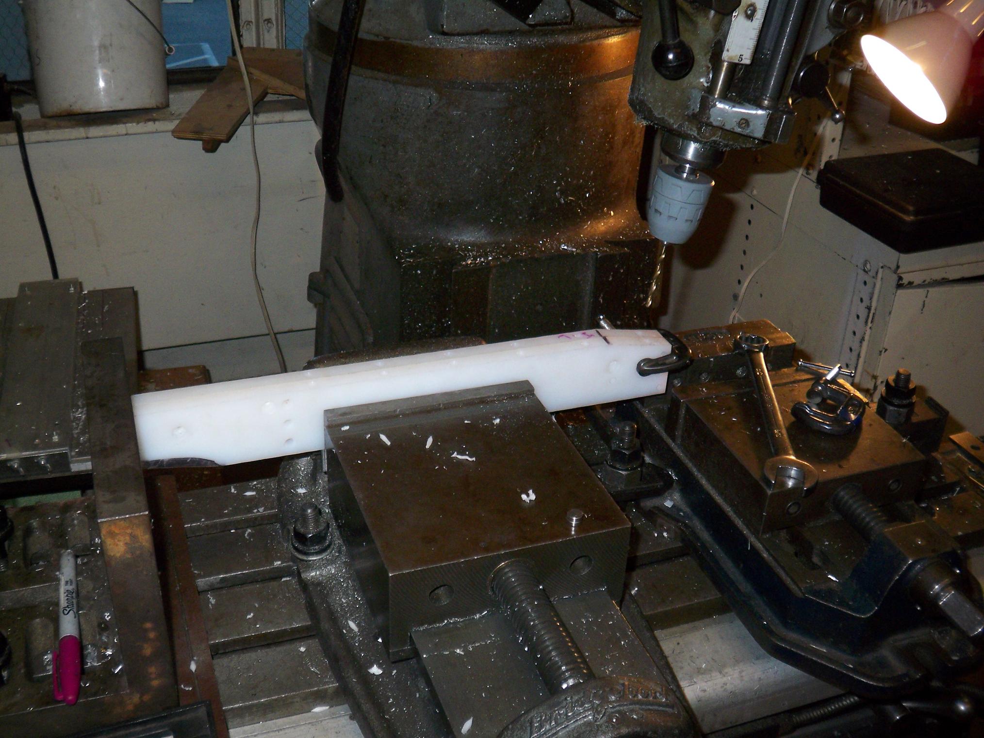
I don’t have enough time during the weekdays to get into any serious work on the bots, but I still do little tidbits here and there since I pass through MITERS more than I should. Überclocker edges one step closer to completion today as I bootlegged in the arm parts on some 1/2″ aluminum plate. This time, the waterjet did not epicly fail, and so I now have proper starting material to finish the fr0k.

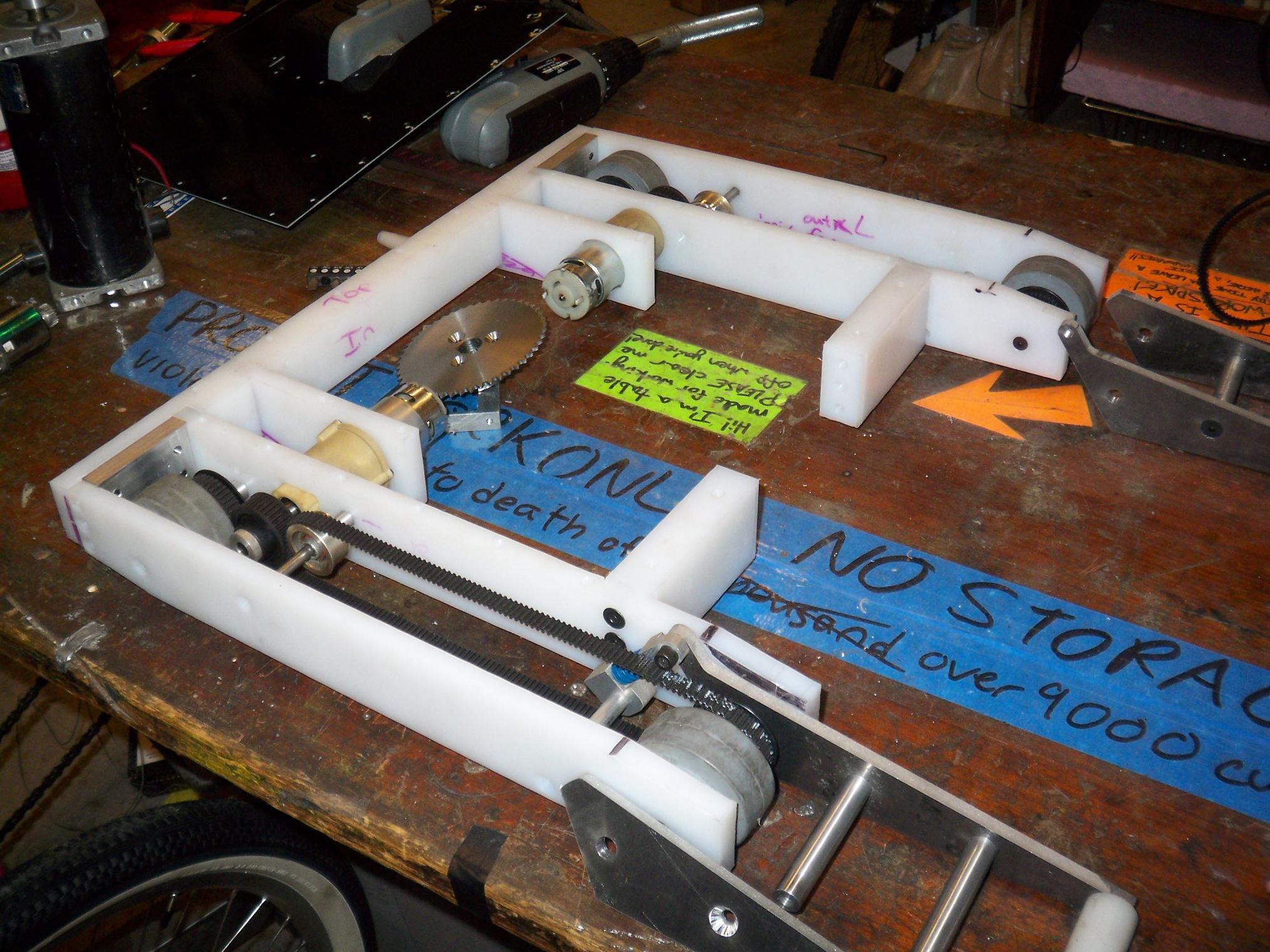
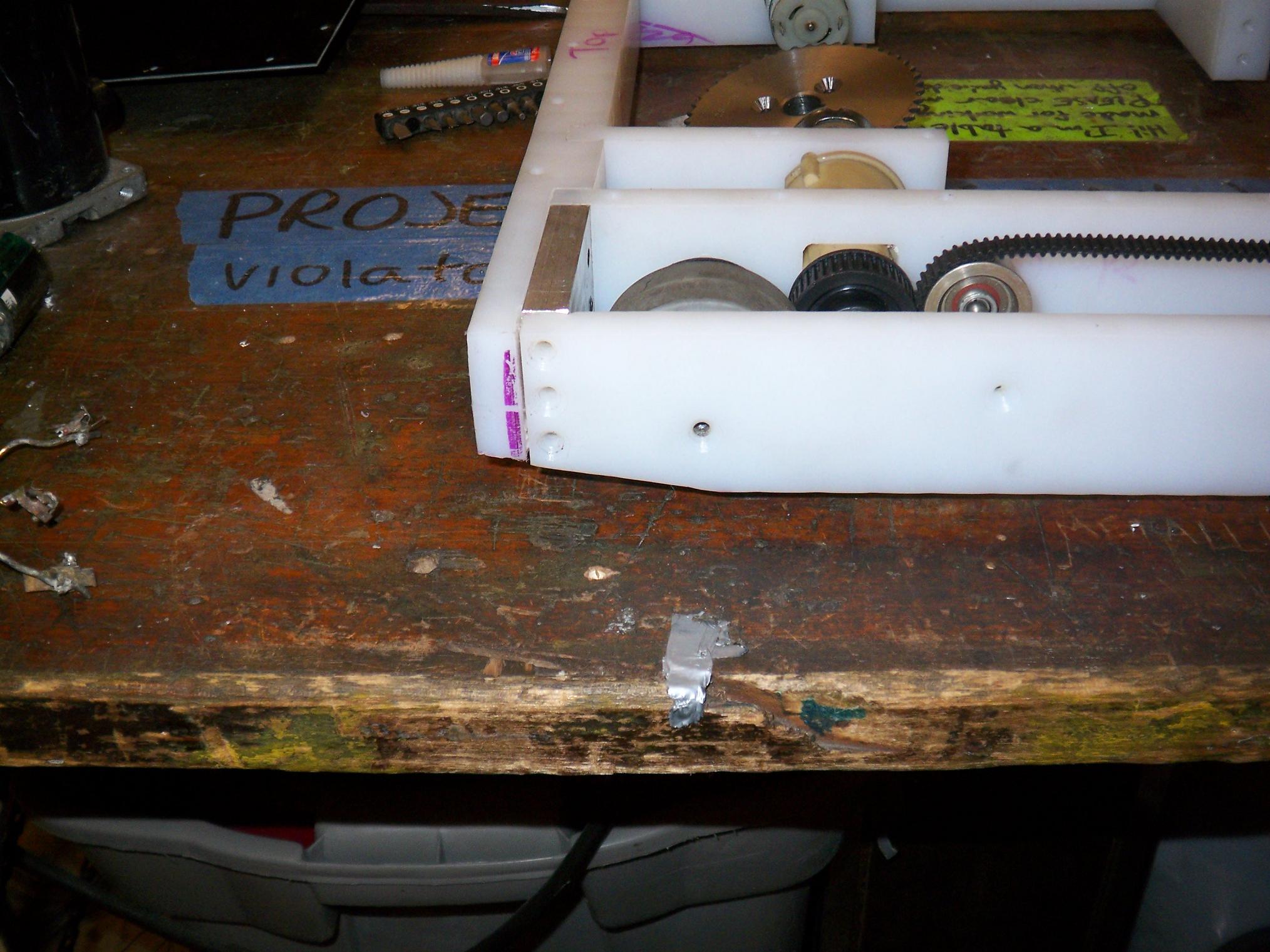
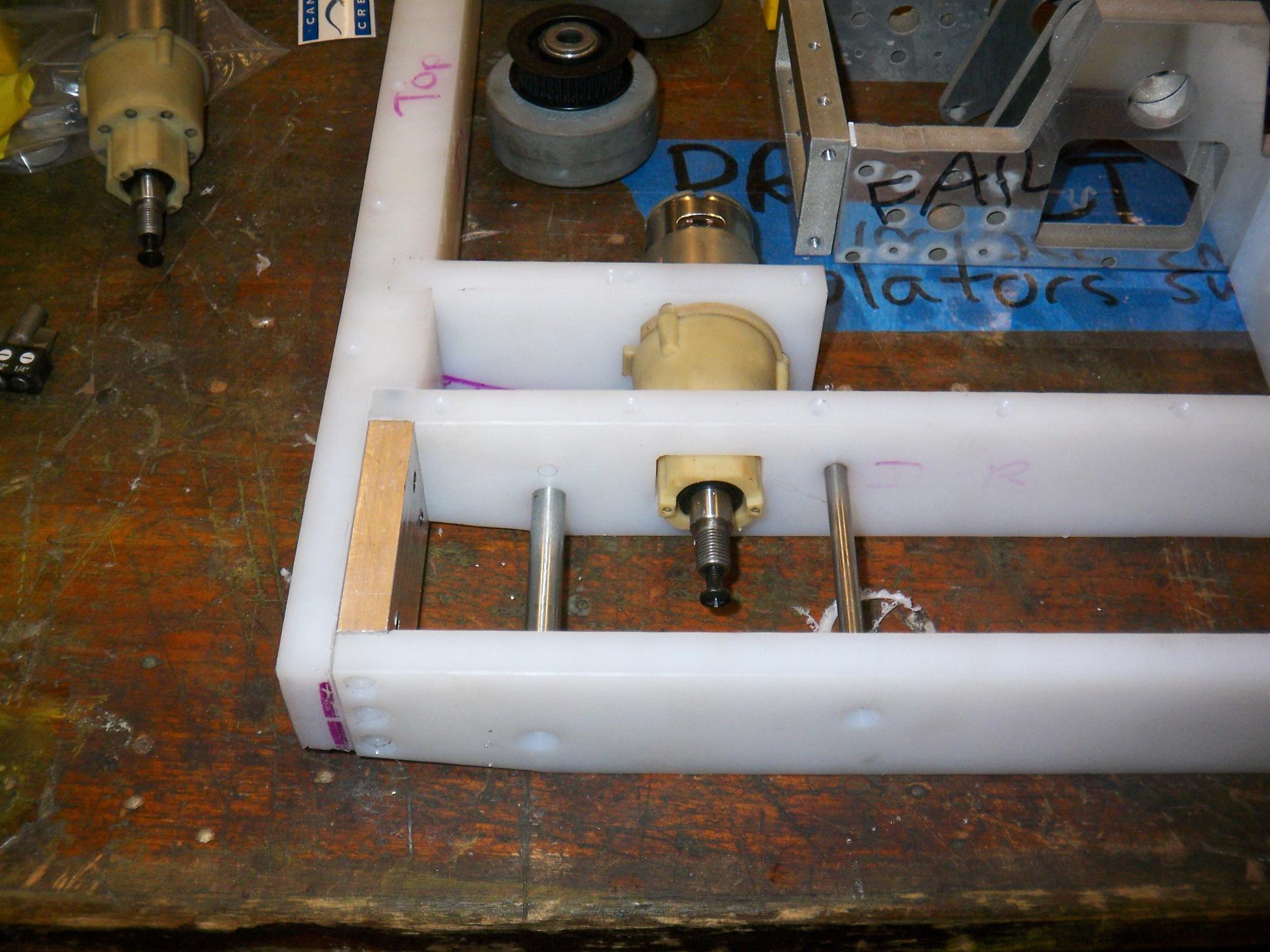
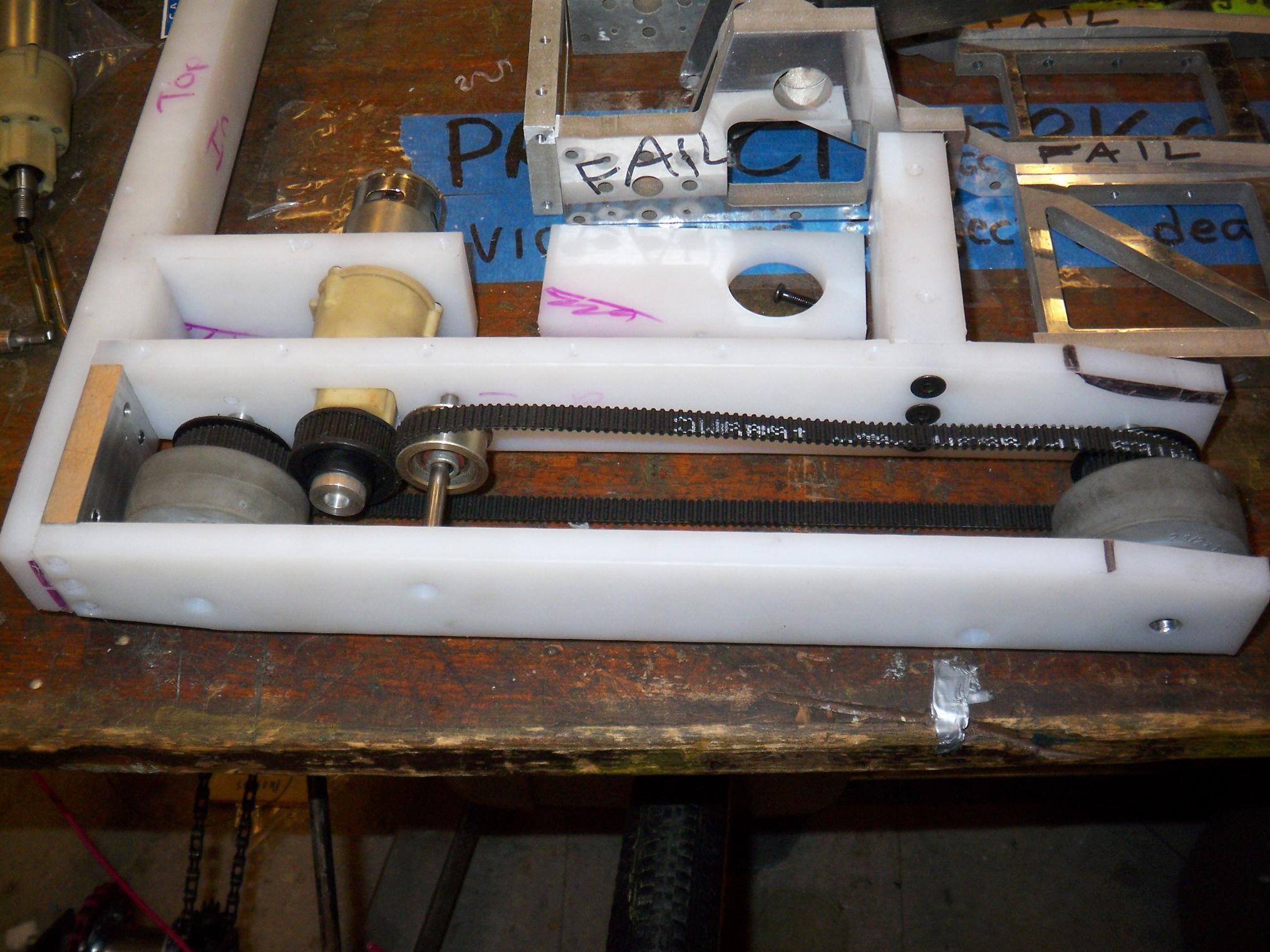
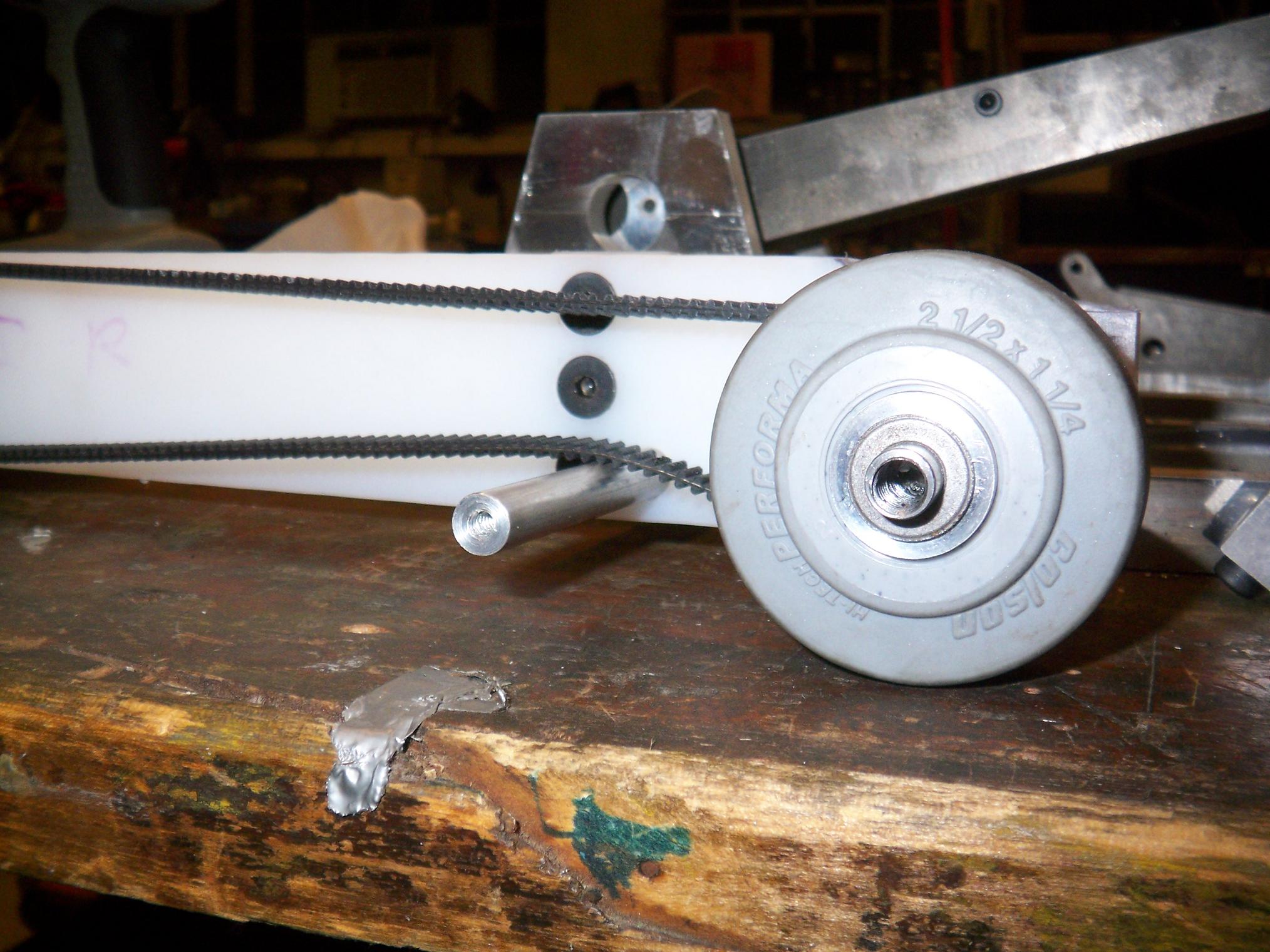
The frame finally stands on all four wheels! About time, too. It’s missing a shaft collar here and there, but a run to the hardware store will solve that. I’m also waiting on a bag of springs from McMaster such that I can finish the left side. I’m satisfied with the belt tension around the rear now that I have modified those rollers to fit on the tensioner axle, but there is of course some stretch and play in the long run to the front wheel.

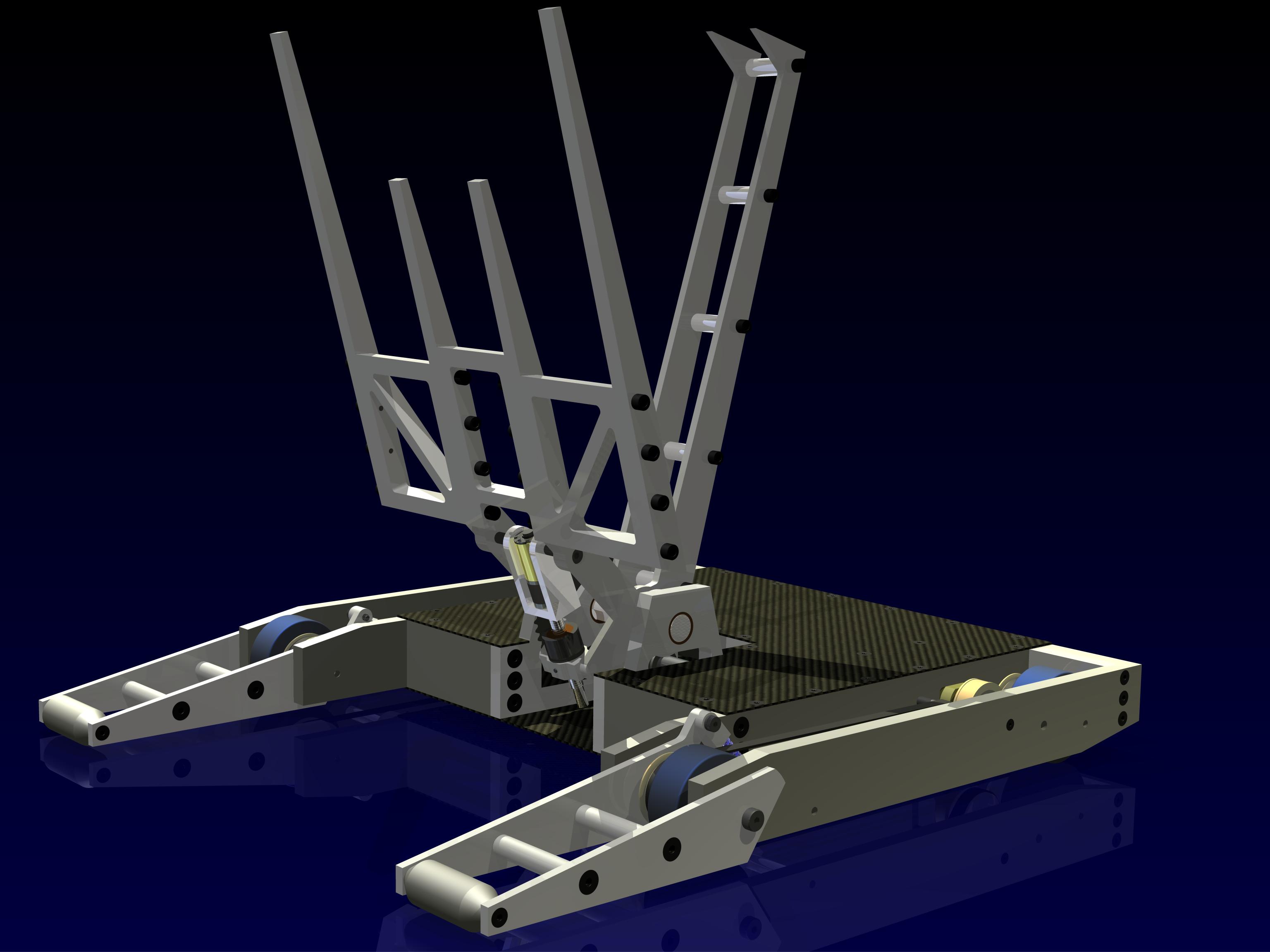
One design feature of this bot that I think will come in handy at Robot Battles is the 10 degree rear bevel. Even though it was an enormous pain to machine, it allows the bot to tilt backwards over 45 degrees without losing traction – unlike my other rather low-riding bots, which are toast if they crawl onto another wedge. It still doesn’t beat the bots that have fully exposed rear wheels, but that wasn’t compatible with the body geometry.

Non-fail parts. They’re not shiny mirror aluminum nor are they actually .5″ thick (more like .515″ – it’s that weird-ass neither-metric-nor-imperial aluminum again!), but at least they have the holes in the right places. Thicknesses can be reduced, but I can’t move an entire regiment of failholes.

These parts only require minor postprocessing like threading, slotting, and counterboring.

So I lied – there was one failjet part, but it was due to my own idiocy of not tightening down the head height adjust, so the cutting head was bobbing around every time it fired. Oops.

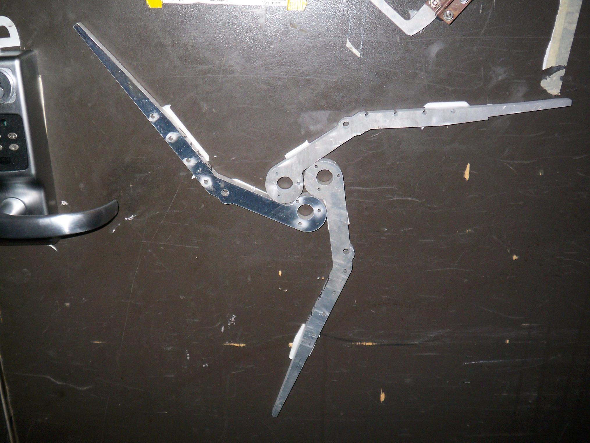
What do you do with three almost-identical shiny metal things that can’t actually be used? Door decoration. This trefoil-like thing now adorns the MITERS front door, along with a giant epic sprocket.

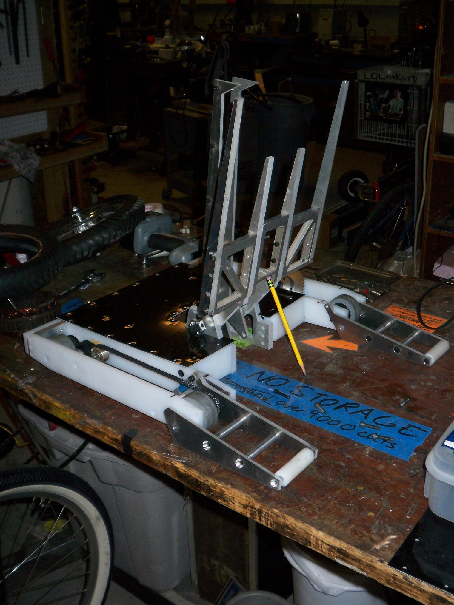
So with all the fr0k proto-parts fitting properly, it was time to prep Überclocker for its first clampbot salute. Slightly rigged, of course. In the background of the picture lurks the fr0k sprocket, which I have bored and drilled, but not yet finished facing. I hope to have the real assembly up and running some time by the end of the weekend.

Weekend? Why yes, it’s almost the weekend. After I emerge from the bowels of MITERS again, I’ll post more pictures. I’ll probably be trapped in there for a good while, since we got yet another toolgasm today.

Überclocker Update 8

I didn’t wake up at 3PM, fortunately, so alot of work got done today. At the rate that I’m going, the bot should be done with a few more weekends of work…which is fortunate, since all I have IS a few more weekends (!!?). This assumes a constant flow of parts and also that I can bootleg the remaining fr0k pieces this week on the waterjet.

Mostly frame-related stuff today. Things are starting to bolt together!

Adding the top and bottom holes to the frame bits. This was sped up alot by the partstops and also the realization that no matter how sloppy I am with the DRO (within reason), it was STILL going to be better than the UHMW’s natural manufacturing tolerances. I took alot of machining liberties with today’s build – some times you just don’t NEED that much precision.

I stopped spending the extra 5 seconds on every tool and hole combination to bump the axis to EXACTLY x.0000 because the drill bit probably has more runout than that anyway.  .002 +/- was enough.

In another episode of “Charles forgets which side of the part he’s working on”, a multiple-y-slotted frame rail. Thank goodness it’s only a 1/16″ deep slot.

After the top and bottom holes were drilled in the inner frame rails, I milled out the drive gearbox mount. The drive motors are mounted by two pieces of UHMW each. The rectangular cutout in the frame rail secures the gearbox nose and prevents the entire thing from torquing. A shorter frame railstub (not yet made as of this picture) with a  1.5″ hole supports the motor itself.

When all the holes were finally drilled, I countersunk them. Despite using the even-fluted countersinks available, I was able to avoid chatter by running a high speed but “slam feeding”, in which I set the depth stop on the drill press and then just give the quill a good downward smack. UHMW is a soft enough material such that the countersink didn’t even have a chance to chatter before being bounced back up, leaving a clean round countersink.

It worked quite nicely. The larger 1/4″-20 screws, however, required that I actually countersink them the normal way, since they were much too large to be slam-fed. They came out slightly less clean.

Also, don’t photograph white holes on white material.

3/4 of the way into the evening, and it was time for a test fit of the frame parts. I used a cordless drill with a spiral point tap to thread all the frame holes to accept cap screws. Spiral point taps are wonderful on UHMW – drill the hole slightly deeper than the required thread depth, and it will squish all the swarf into the bottom of the hole, leaving clean threads and no debris on the tap.

In and out in under 2 seconds per hole.

Verdict: Yes, everything fits.

Here are the motor-retaining frame railstubs. The gearbox section is trapped axially between the two walls of UHMW and retained rotationally by the rectangular cutout. It’s a snug, but not tight fit, and the motor can wiggle a bit. I might just let it float like this, or I might drop some small set screws in to secure the motor.

At this point, I could finally test the fit of the belts. Because the belts were spec’d out based only a crude pitch circle measurement, I was concerned that they would be either too tight or too loose. Result: slightly too loose, but there’s no size immediately under 265 teeth that I could find (250 would be very much too short). However, using a belt tensioning pulley with a large-ish diameter (as shown) mitigates the problem.

Adding the outer rails makes it better, since the belt would bend the axles inwards slightly without. Centering the bore of the tensioning pulley puts the belt at an acceptable level of tension – I’m mainly concerned about the motor pulley slipping, but with pulleys that large surrounding it, I doubt it will be a problem.

In an absolute emergency, I could make a “low side tensioner” using the 3/8″ rod that the front support springy things pivot on.

So, Pretend-o-Bot for Sunday evening has the UHMW frame complete, the first subassembly of the bot to be finished. The right side drive is almost done, needing only spacers, and the left side drive needs matching parts. After that, it’s all fr0k work and electricals (time to start experimenting with custom servos…)

Überclocker should be completed on schedule with mid-August as the target.