I have taken over 100 pictures of the build. I take an excessive amount of buildpics.
This is actually not a bad thing. I have grown to like documenting my work as much as I can manage. You know, so in case I lose my memory for some reason, I can find out how to do it again.
Yes. Anyways…

More drills! I got some more 18 volt drills off mysterious, sketchy Yahoo Stores. Oddly enough, now that I’m actually looking for a 18v drill with the standard 36:1 gearbox, I can’t get one. Yes, these are the 900RPM type. Handy if I want to have a spare gearset for the drivetrain (which I do).
So, for the curious, the Great Neck “brand” of imported 18 volt drills also have 24:1, 900 RPM gearboxes. I’ve seen these at multiple retailers, like this.

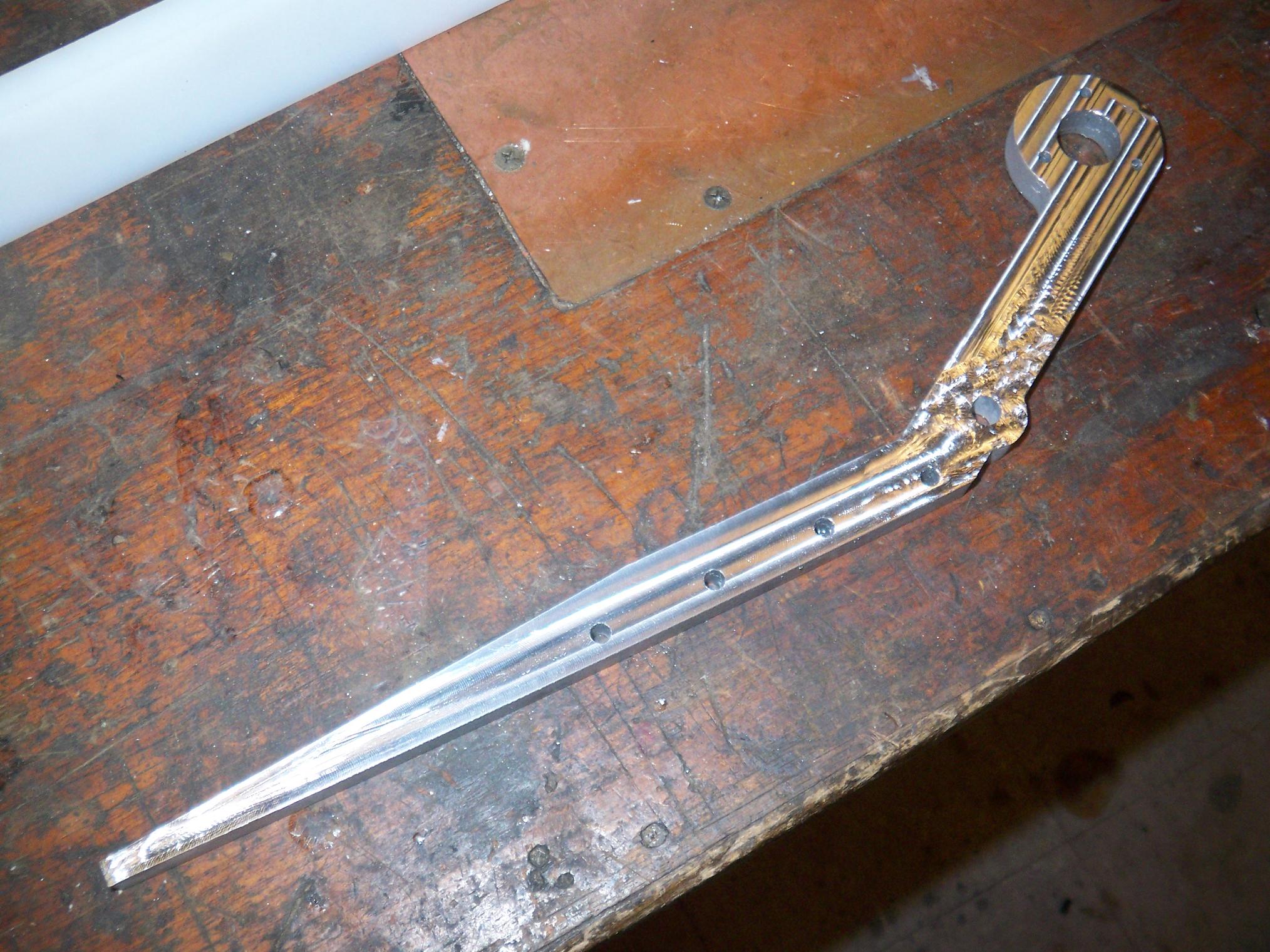
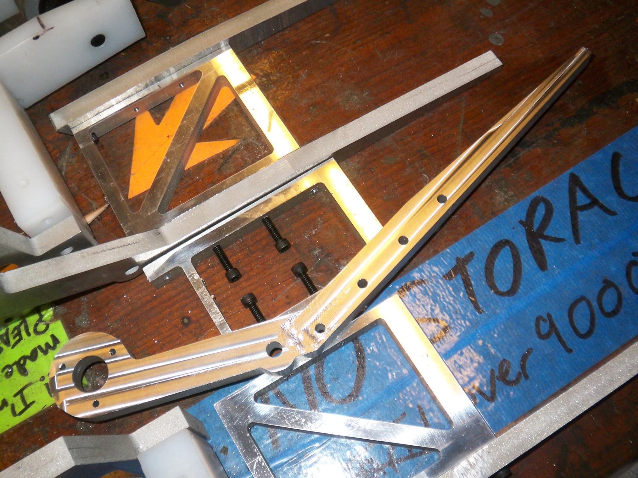
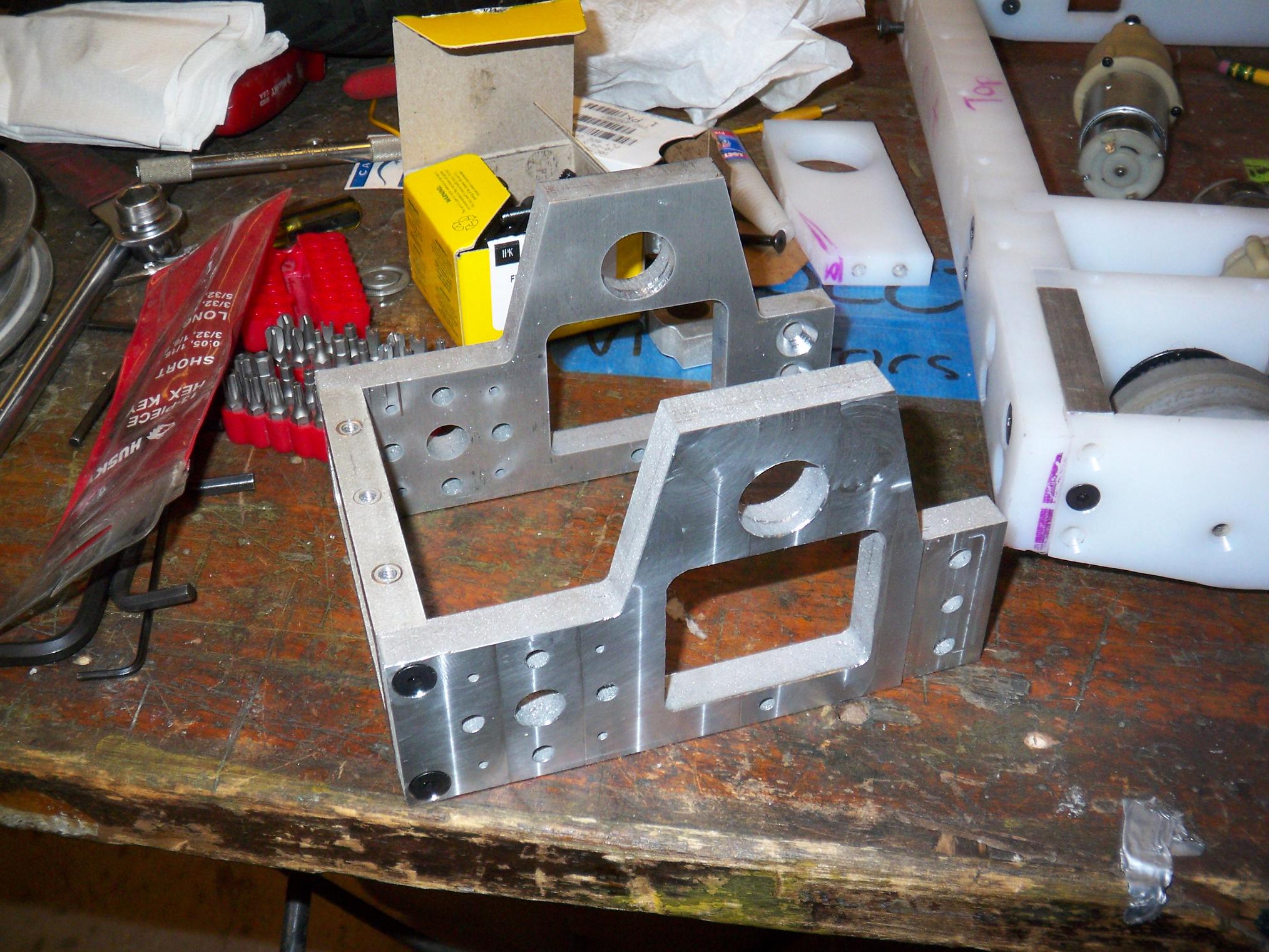
Down to business. I couldn’t find any 4-40 cap screws, so I had to assemble the clamp actuator temporarily with little computer standoffs. Here it is mounted to its pivot by a shoulder screw and spacer (one of my new favorite building methods). The actuator is free to swing on the pivot point.
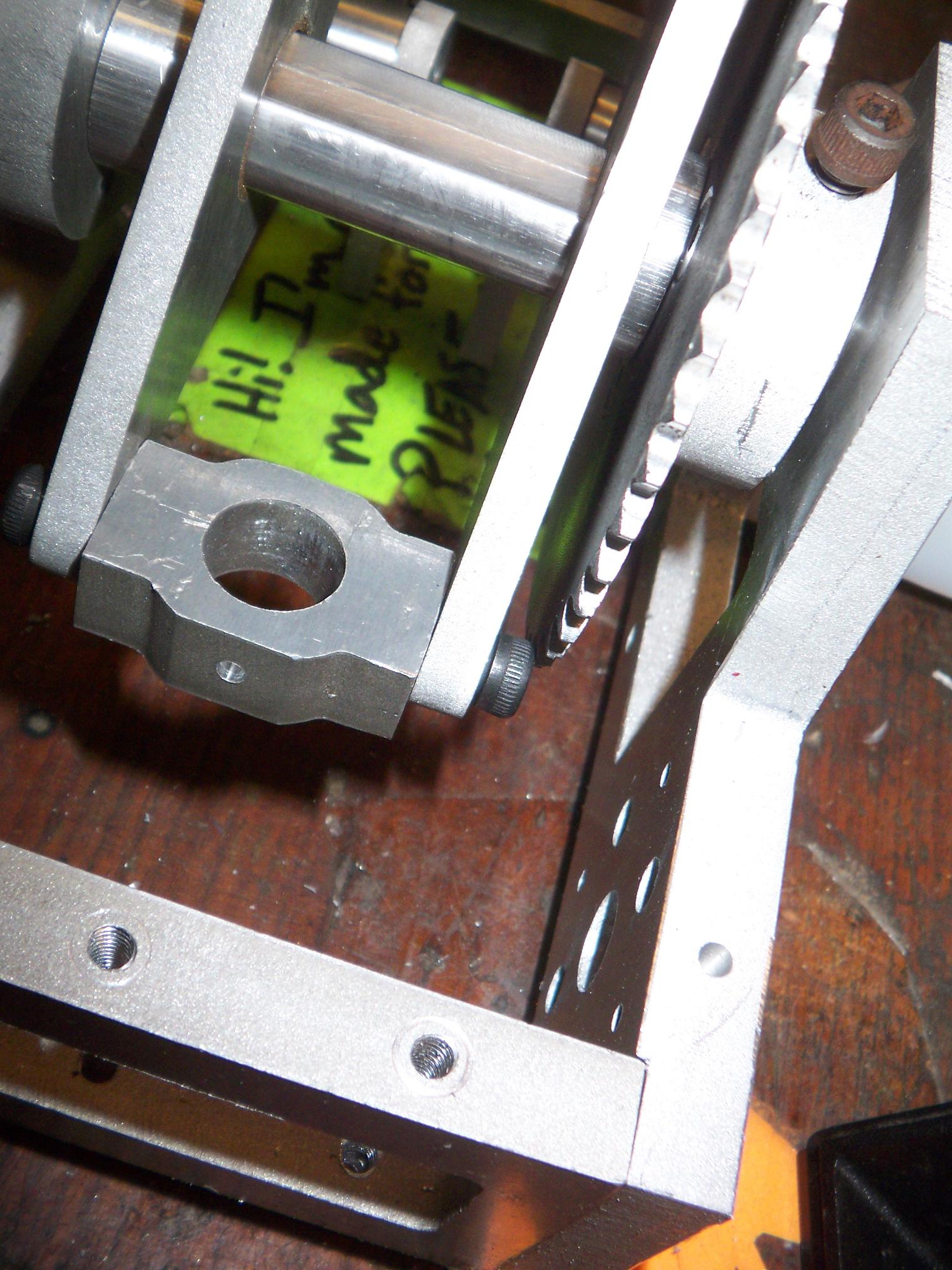
In yet another episode of “How the hell am I going to put this together?” I discover that screws do indeed have heads. This one contacts the sprocket, and will need to be counterbored a bit into the clamp arm in order to pass the chain later on.
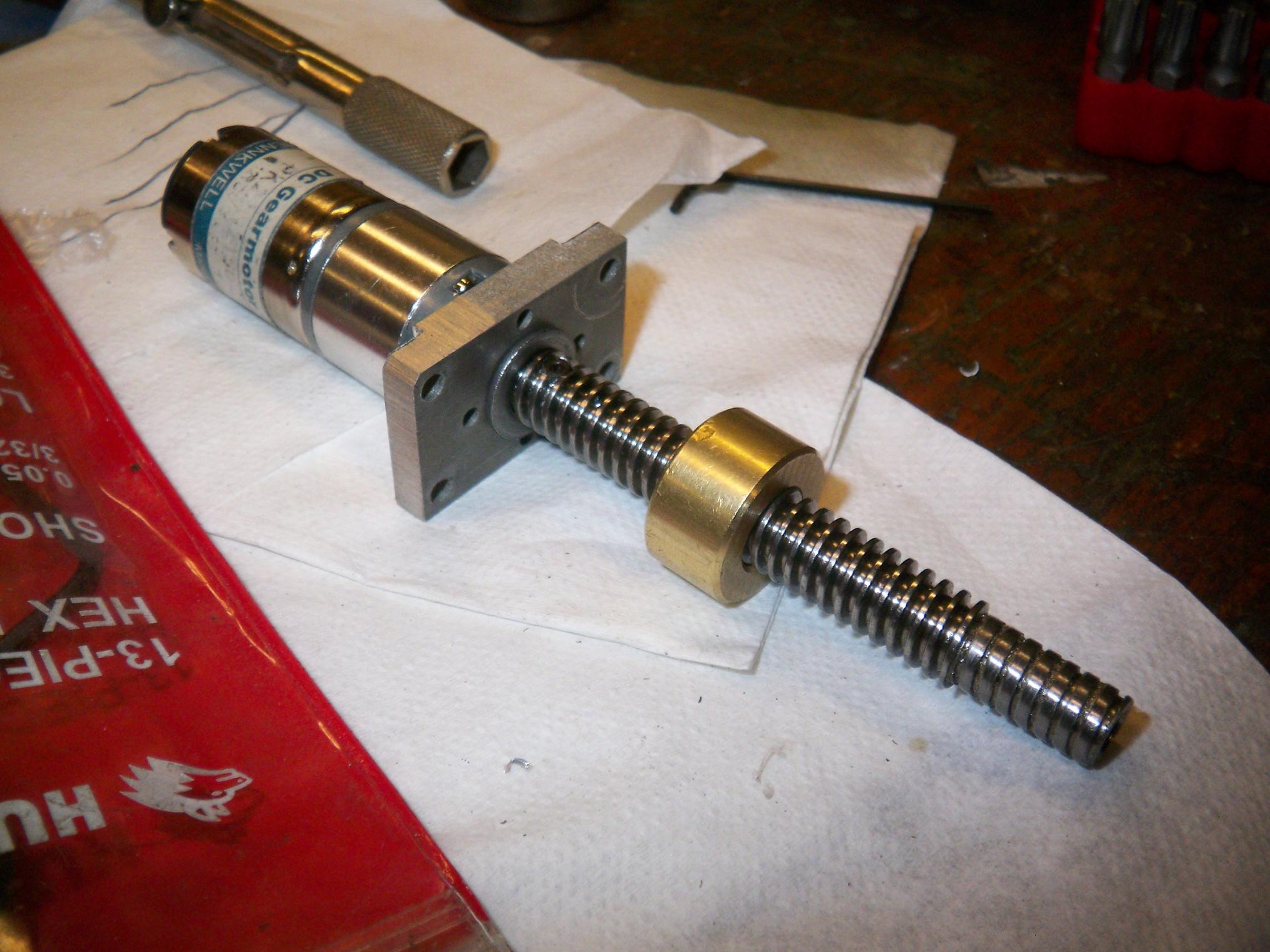
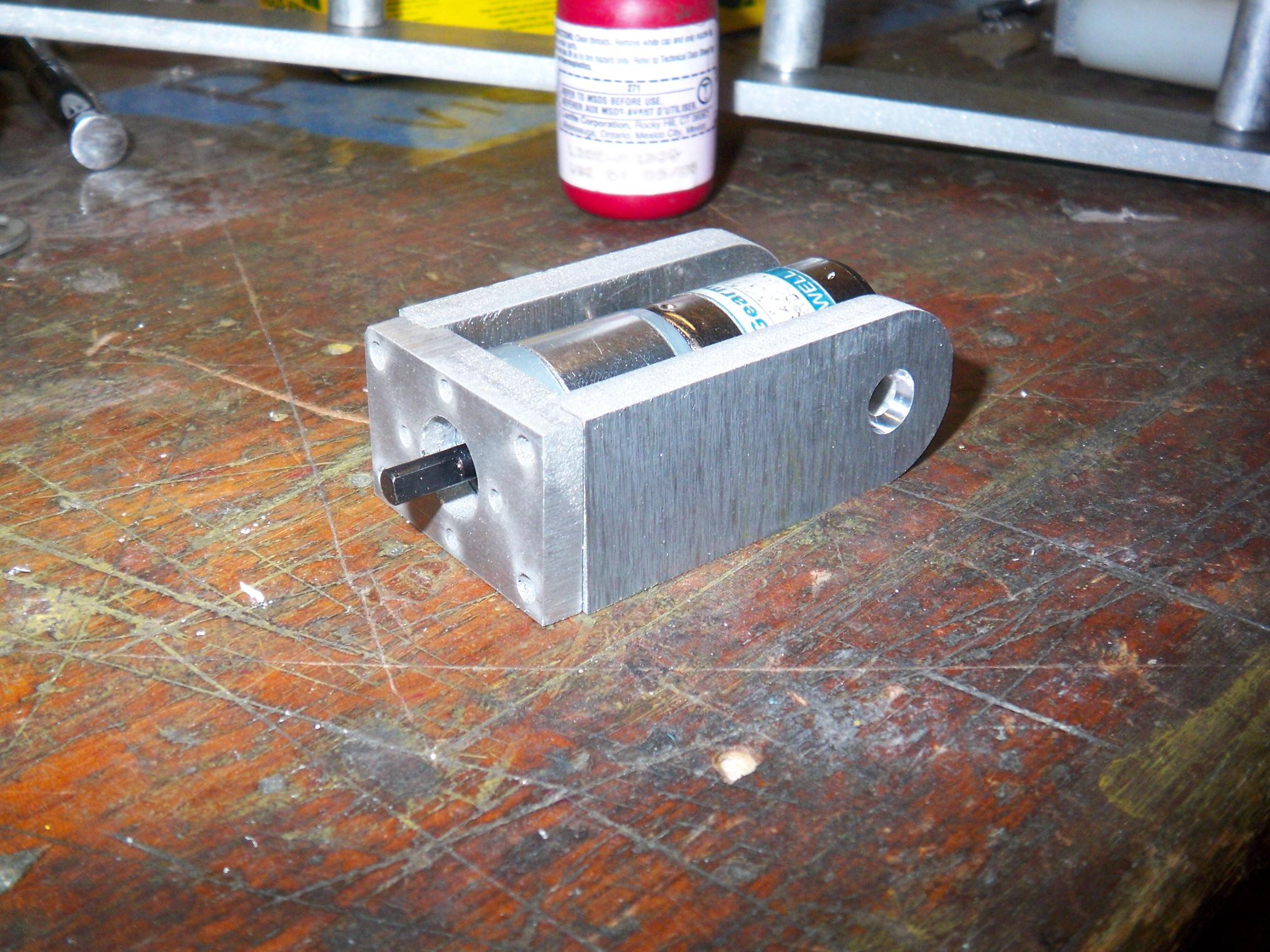
Onto the actuator again. Here’s the beginning stages of the leadscrew assembly.
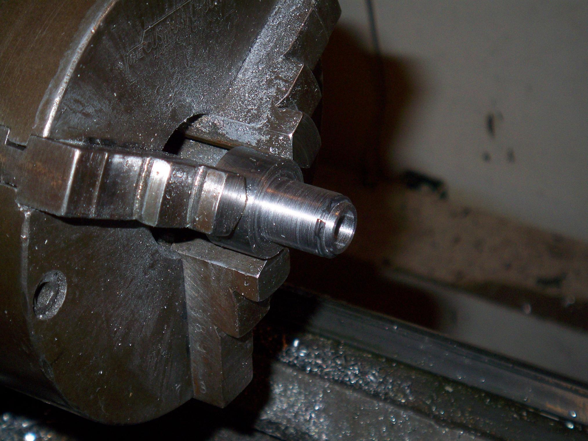
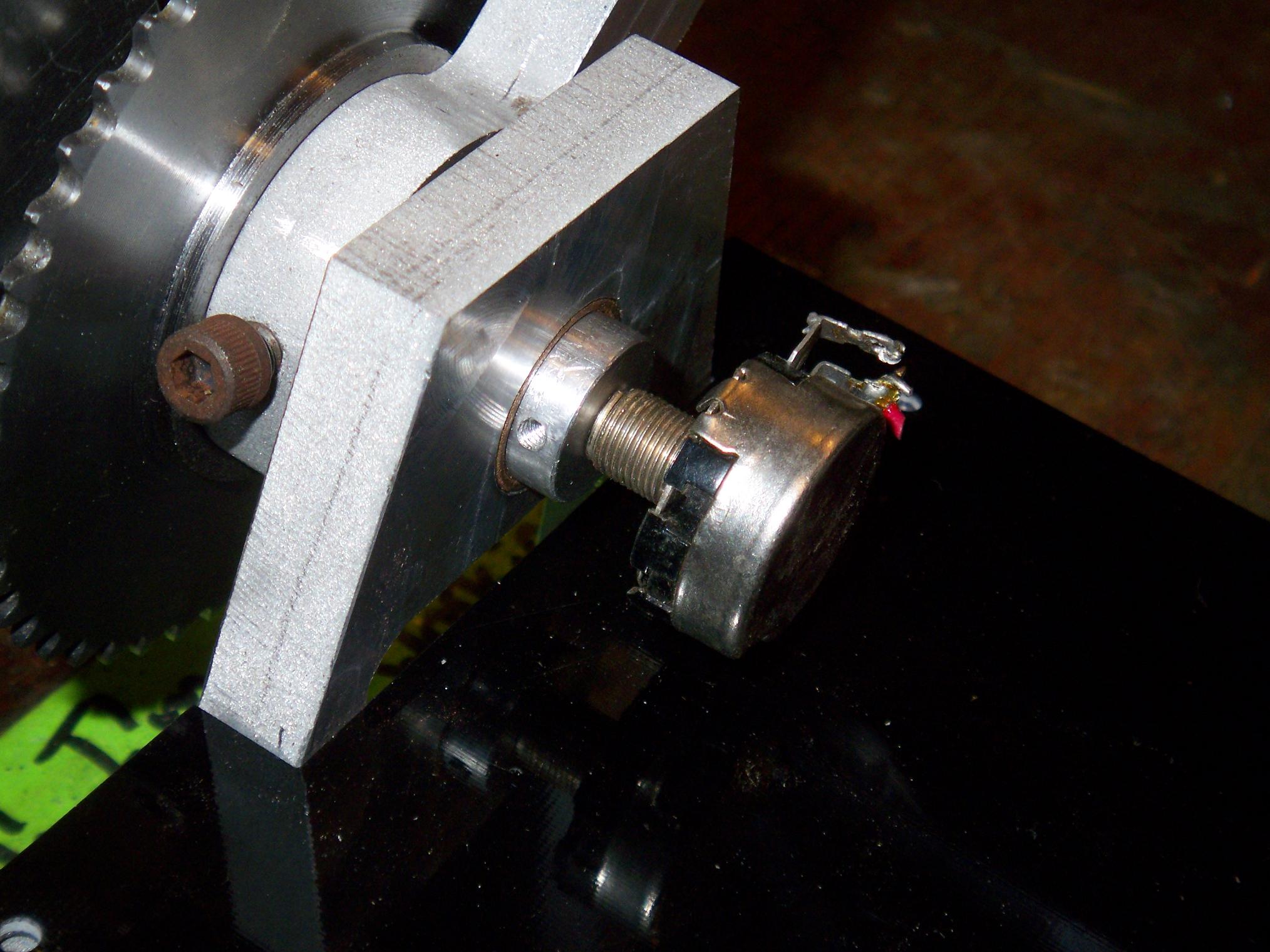
The 3/8-12 Acme screw has one end slightly turned down and bored to fit the 4mm shaft of the B62 motor. A 6-32 set screw drilled down from the screw surface holds onto the shaft flat and transmits torque (You can see it barely sticking up by the bushing).
This turned down section also runs in a short 5/16″ bushing. So, between the B62’s output bearings, the close 4mm shaft fit, and the outer bushing, the screw itself is pretty stiff.
The other end of the screw is also slightly turned down for… Well, I don’t know. It must have been for something.
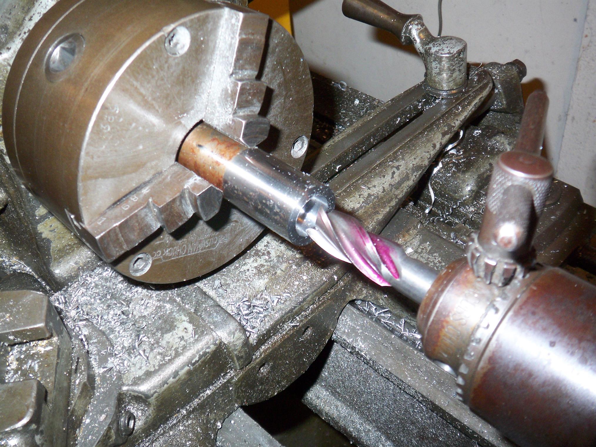
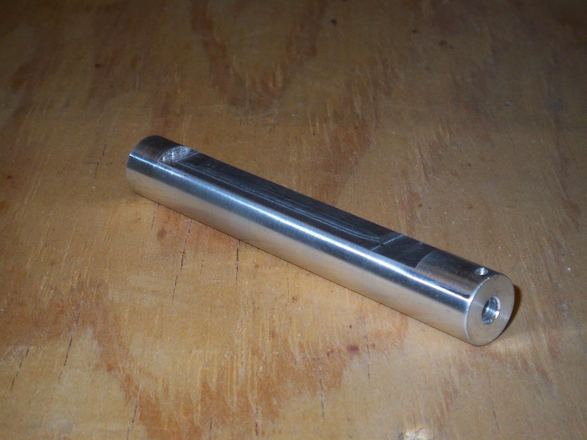
With the leadscrew firmly stuck on the motor, it was time to work on the other end of things. The clamp hinge-pivot-clevis-trunnion-whatever is a multipart assembly consisting of the leadscrew nut, a nut holder (LOL U SED NUT), and the aluminum cutout of the pivot block. The nut holder is made of a 1″ round of steel.
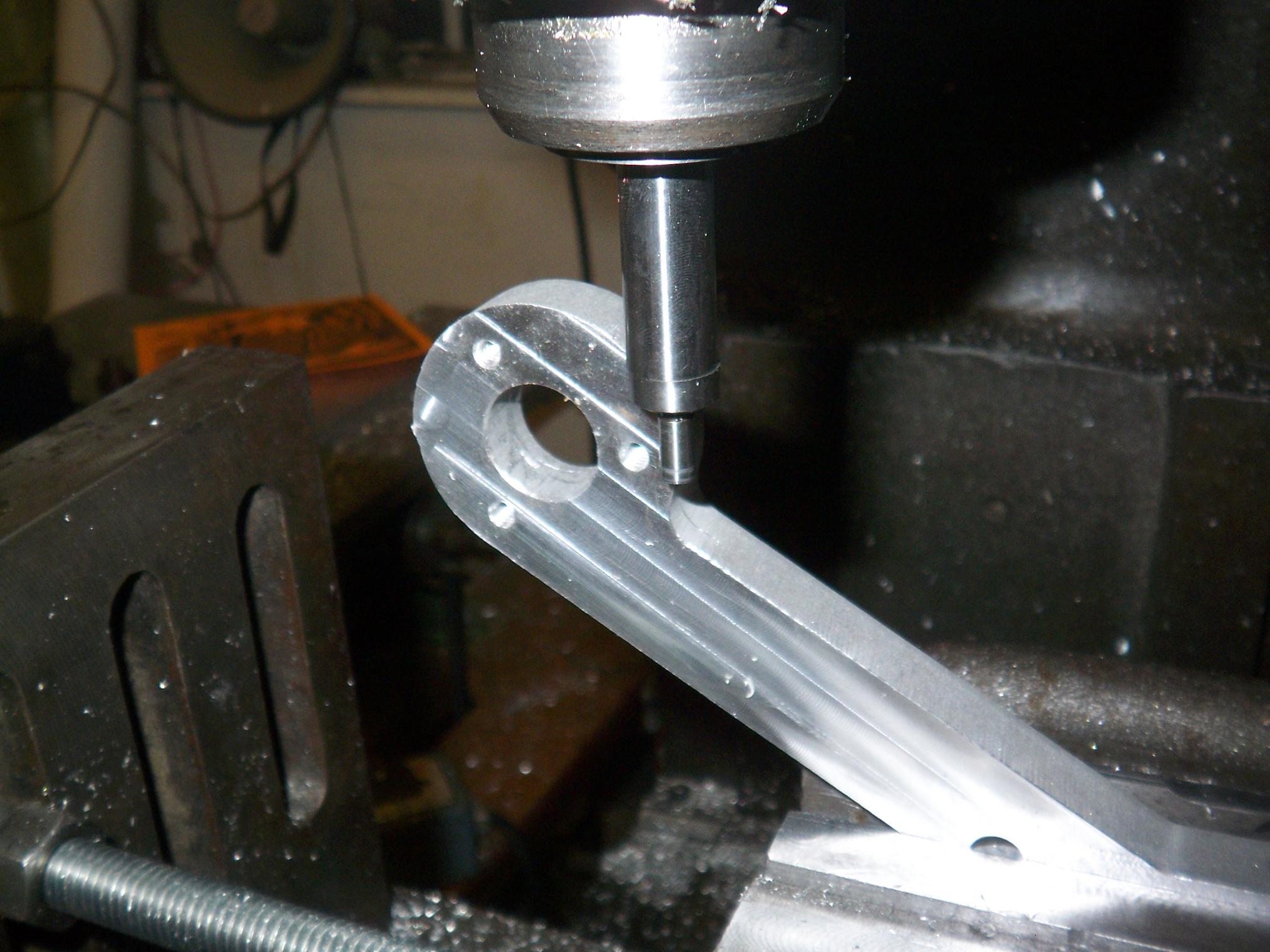
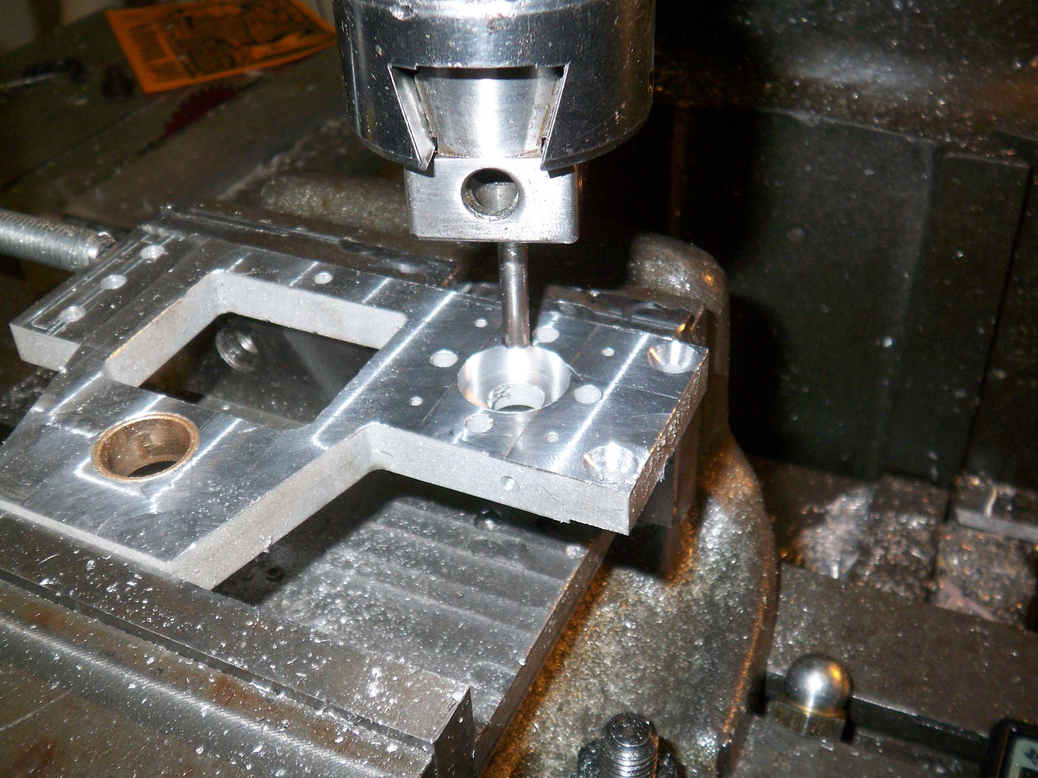
Yes, I chucked an endmill and was using it to drill holes. How else can I get smooth, clean, flat-bottomed holes in a single shot?
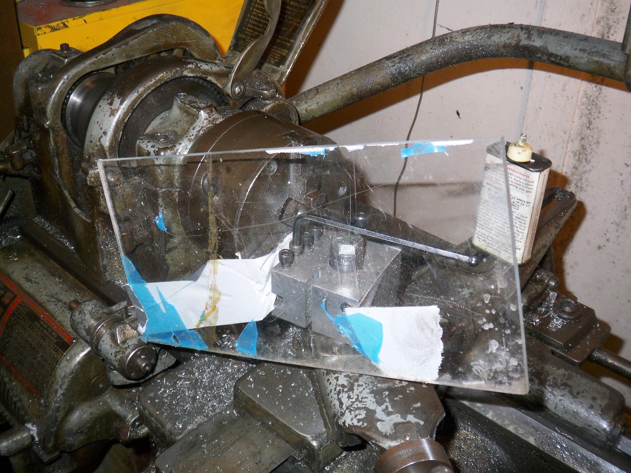
So things got a little too hot during the turning process (by which I mean I was jumping back every few seconds because another smokingly hot oil-covered steel curly sliver would land on my arm). Using mad engineering skills, I make a convenient chip guard.
The lathe stepped up the game by firing chips under the guard. I bit it and just put on some welding gloves.
To keep the assembly together, I turn to my perennial nemesis, the retaining ring. I hate retaining rings with a passion – that’s why I use them, of course. To ease my suffering, I actually went and bought a set of retaining ring pliers with interchangeable heads.
Conveniently, a giant hacksaw blade measures in at the exact right width to cut a slot for this retaining ring. And so the Amputee’s Cutoff Tool was used to slot the nut holder (with the spindle running, duh).
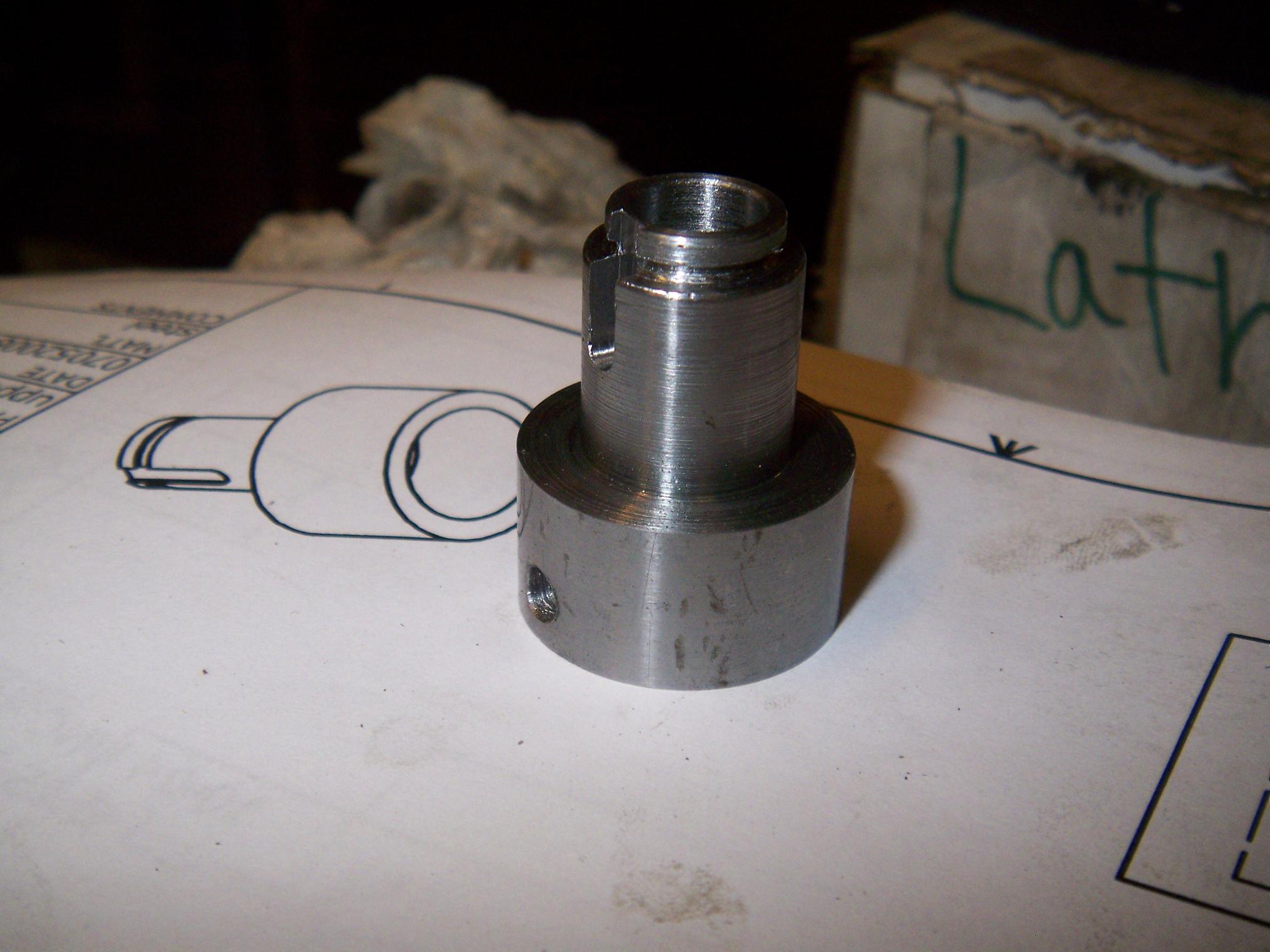
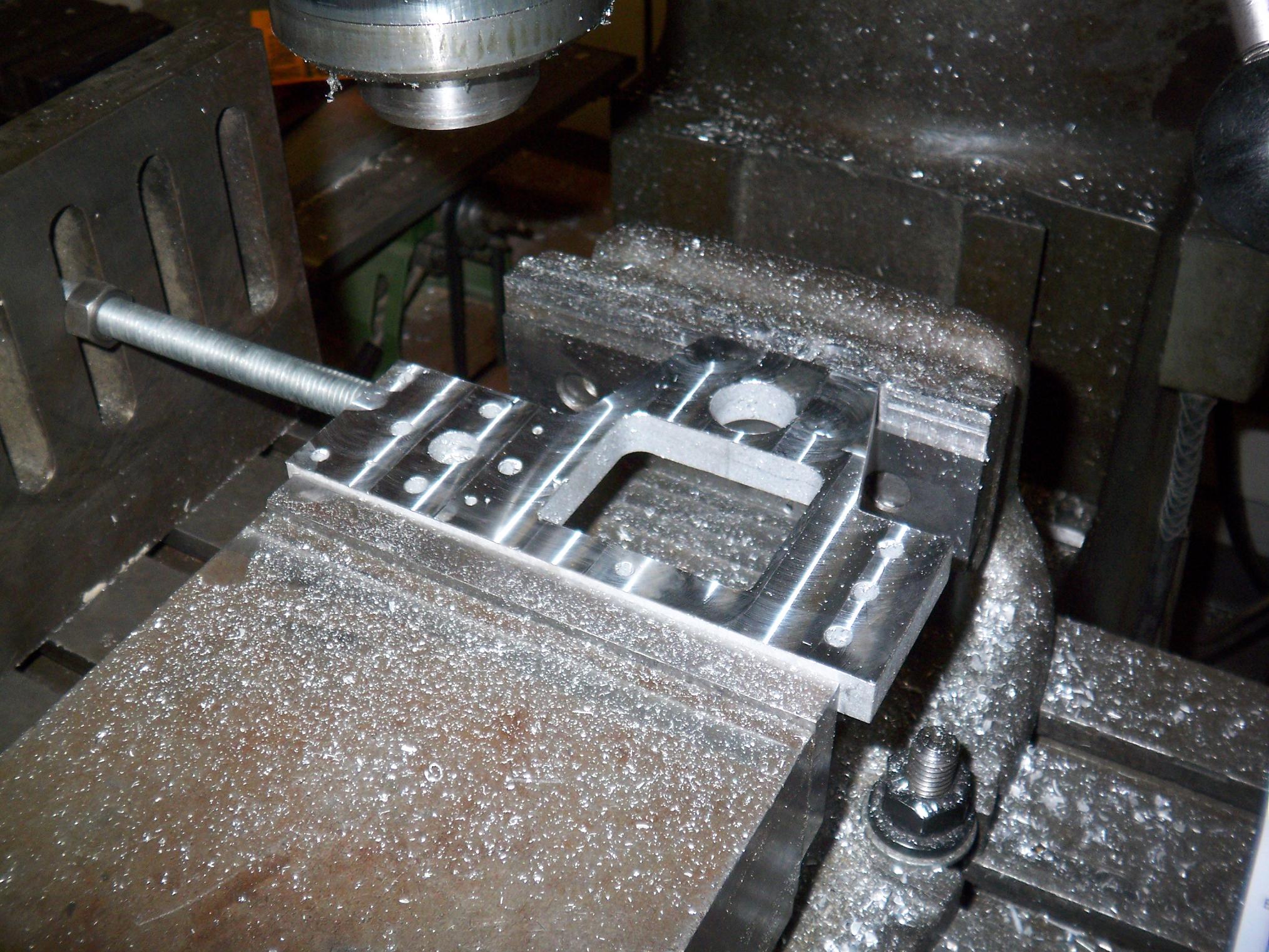
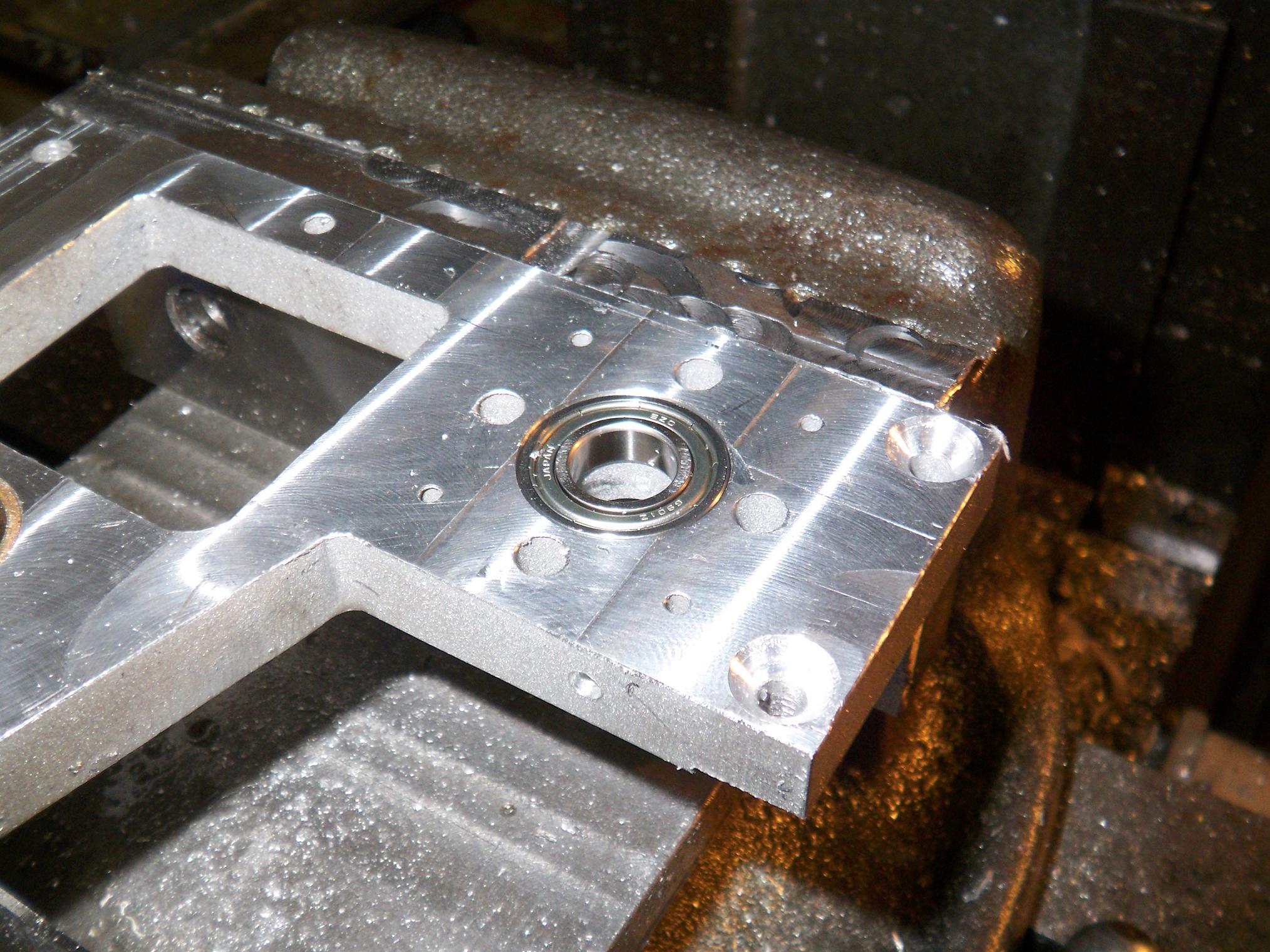
A quick trip to the mill to add a hole and a slot and I have a nut holder (so I don’t have to hold my own nuts, of course). The hole is an on-the-fly part design change, since I figured a press fit was nice but not very serviceable.
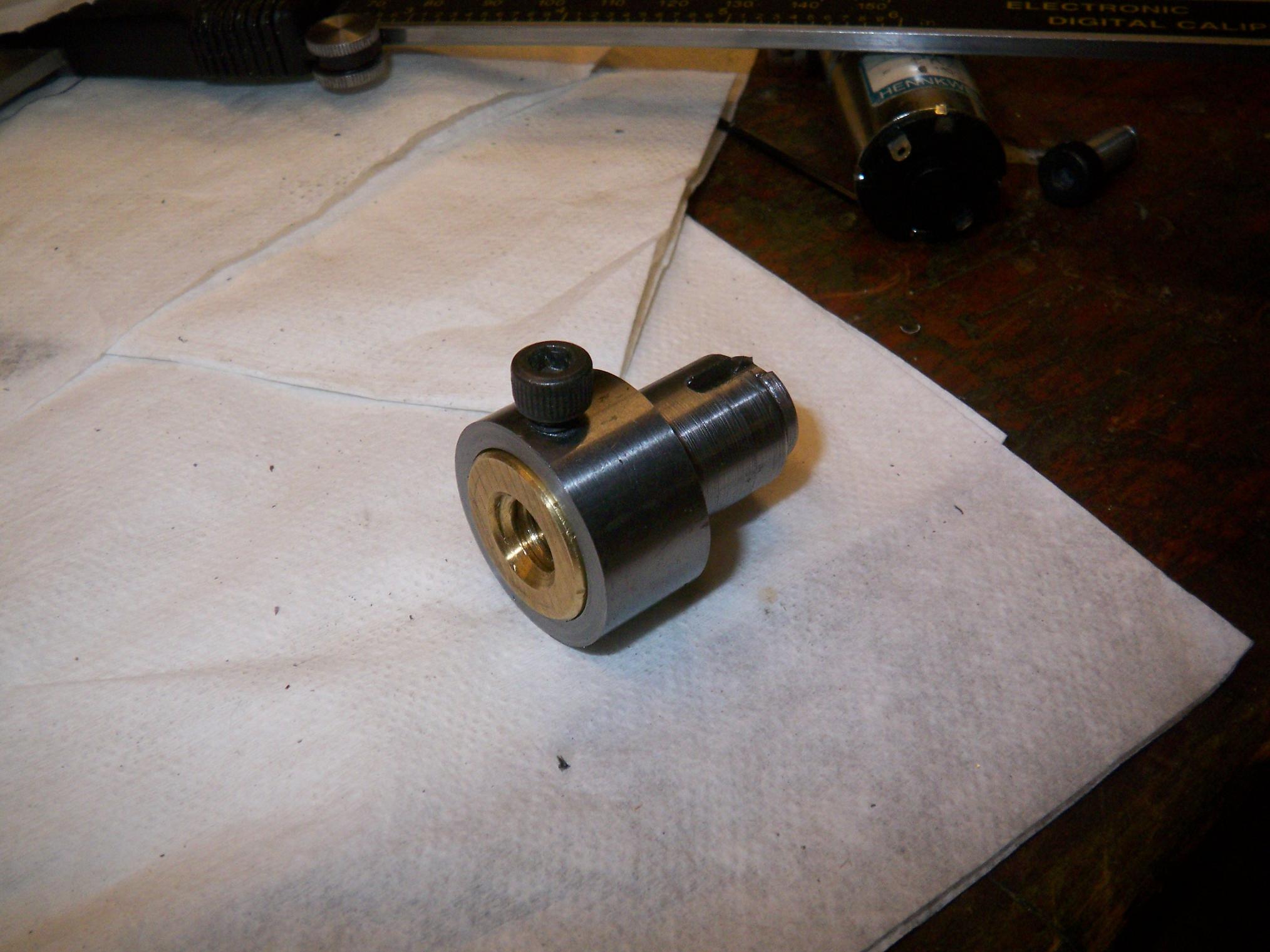
Add one leadscrew nut. A set screw keeps the nut in place. Since this nut should only ever see a compressive load (lifting robots with the clamp arm is a bad idea), I don’t count on this being too much trouble. However, it’s equally less trouble to drill the set screw hole into the nut itself, so that might happen some time too.
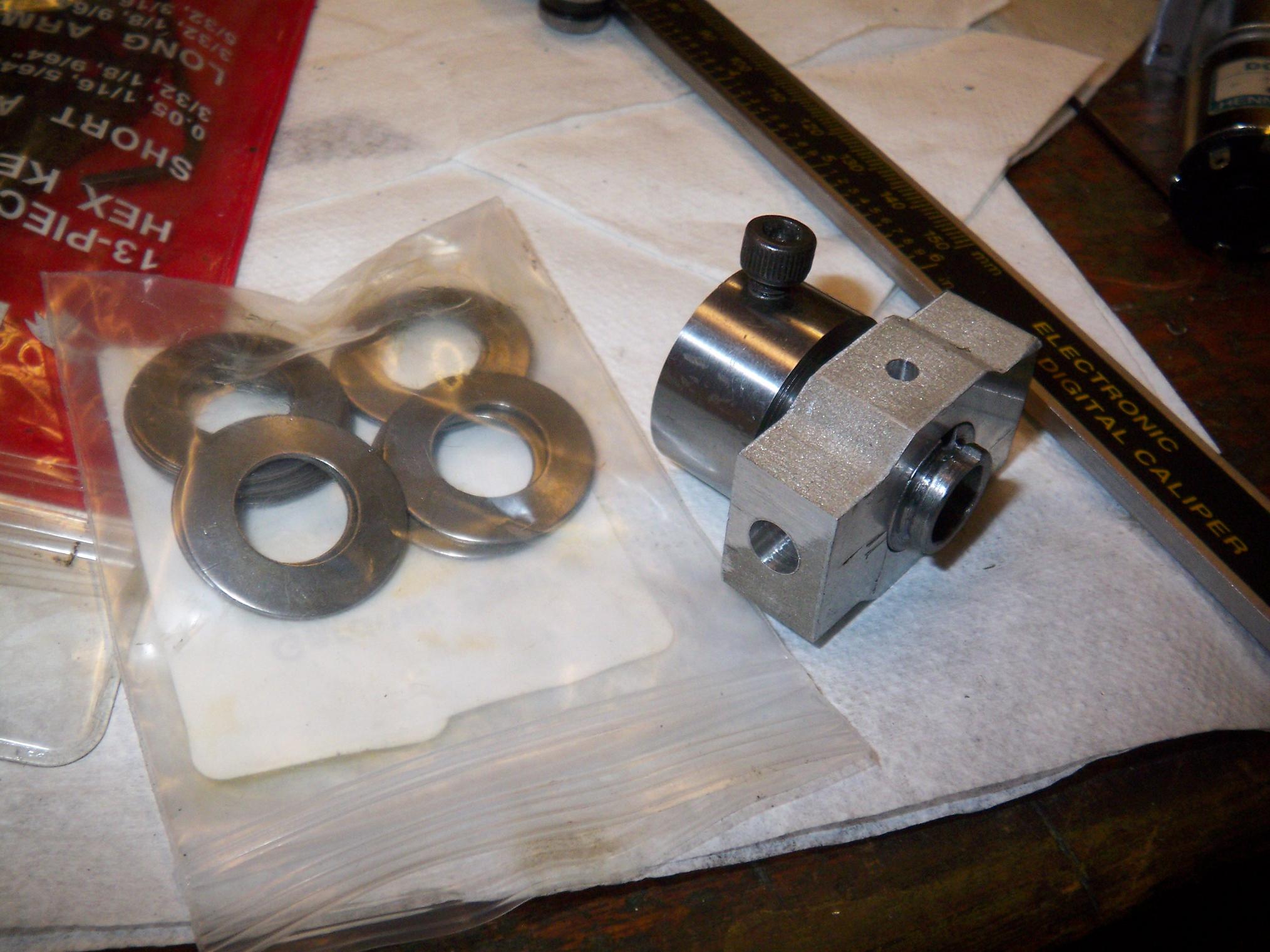
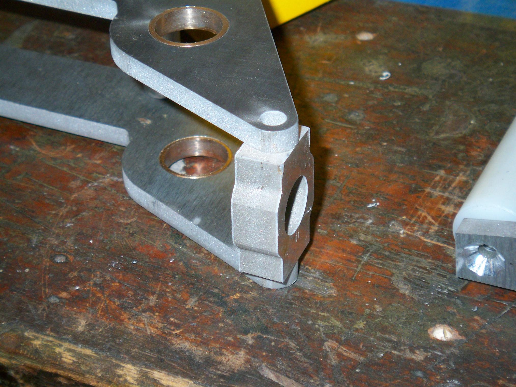
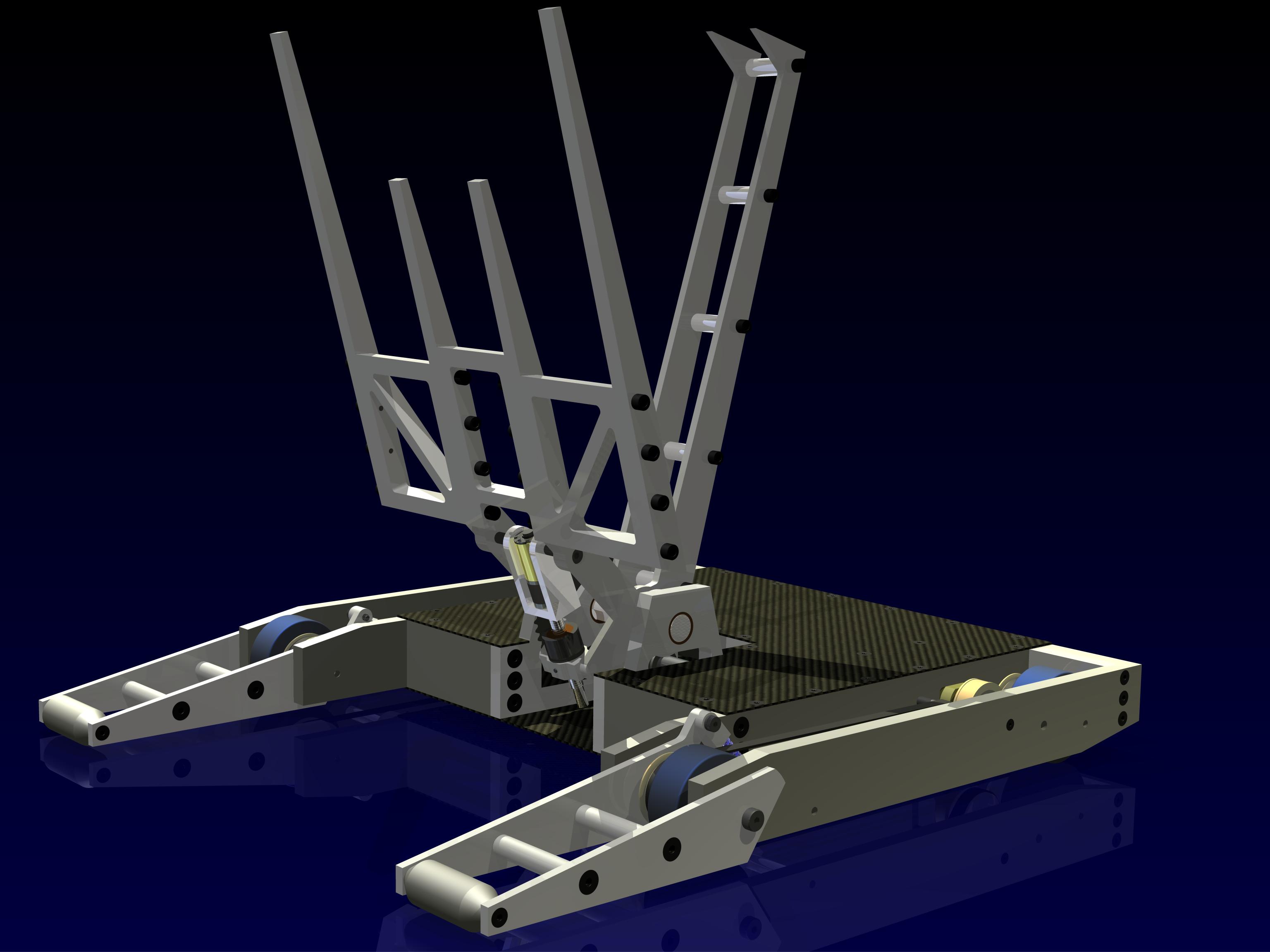
The 100th Ãœberclocker build pic is of the nut assembly. Add to the nut holder assembly the pivot block and two Belleville discsprings, and it makes compliant clamp arm. When the arm clamps down onto an opponent, the motor will continue to drive the nut assembly (since it floats in the pivot block, held in by the retaining ring), compressing the springs and adding a bit of “preload” to the clamp arm. This means the entire system doesn’t have to be wound up in order to clamp firmly.
It adds a bit of compliance to the system, but is not designed to save the assembly if the opponent decides to force its way out of Ãœberclocker’s grip. The next failure point down the line is the end of the clamp arm itself.
Unfortunately, I couldn’t actually test this part, since I redesigned the nut holder on the fly. Originally, a bronze bushing separated the pivot block from the sliding nut assembly, and the neck of the nut holder was 1/2″ – which is what I ordered springs for.
However, in a fit of laziness and after discovering I didn’t order these bushings, I just decided to make the neck a bit wider and run it directly in the aluminum. It’s moving all of 0.1″ maximum – does it really need bushings? There are things in this world that don’t need bearings since they won’t last long enough, move fast enough, or need enough precision to warrant any (Ãœberclocker’s clamp arm is all 3).
Of course I forget the springs no longer fit – time to get different springs.
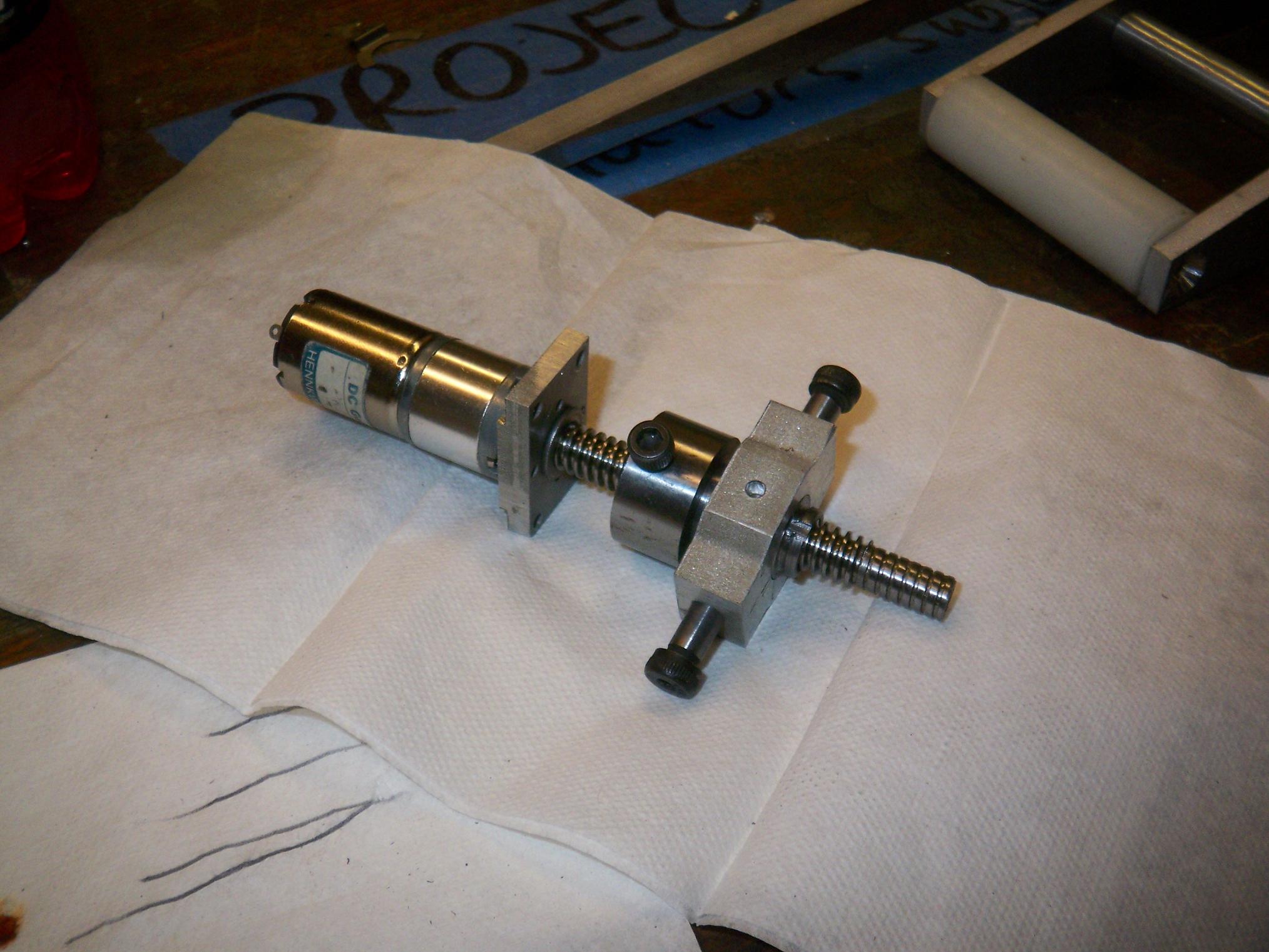
Shoved onto the leadscrew assembly, the (almost) complete clamp actuator. I don’t have the little metric screws to mount the B62, nor 4-40 socket head cap screws to attach the actuator body.
However, it’s fun to just putz the thing up and down the leadscrew. I didn’t get the “precision” Acme nut and screws, but it’s still very smooth, and can push with an absurd amount of force – theoretically over 200 pounds (translating to about 30 at the end of the clamp). Dunking it in some EP grease should make it even better.
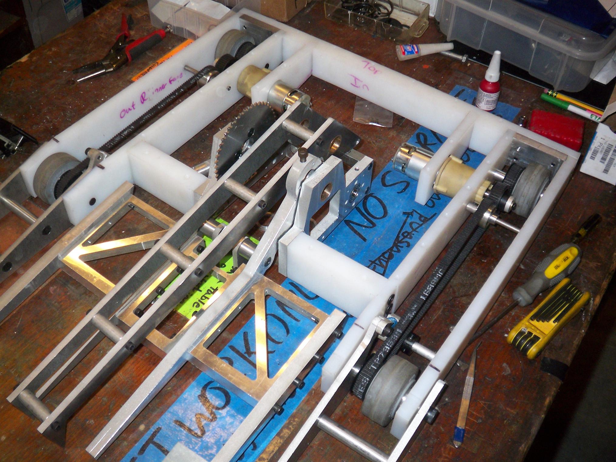
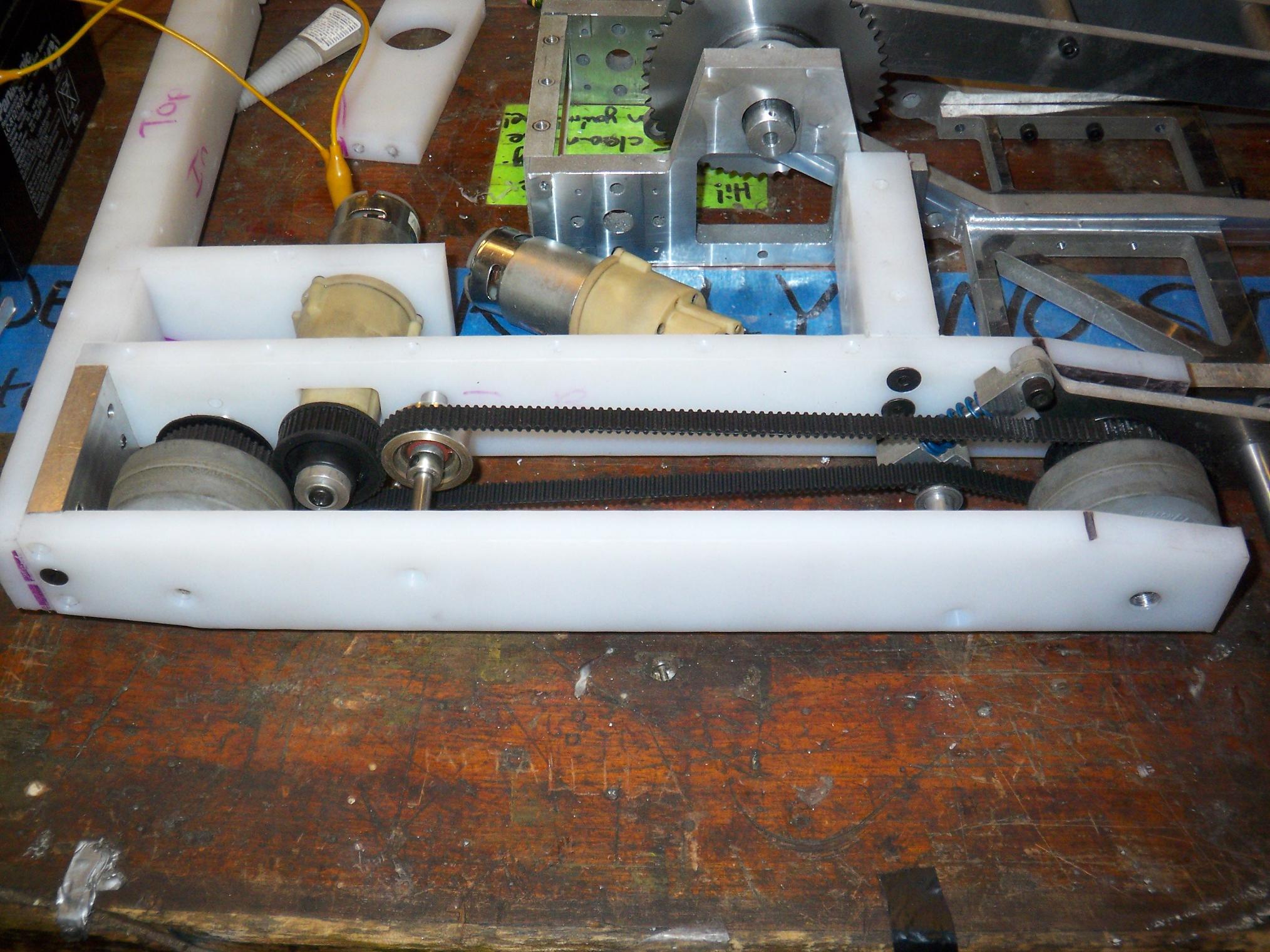
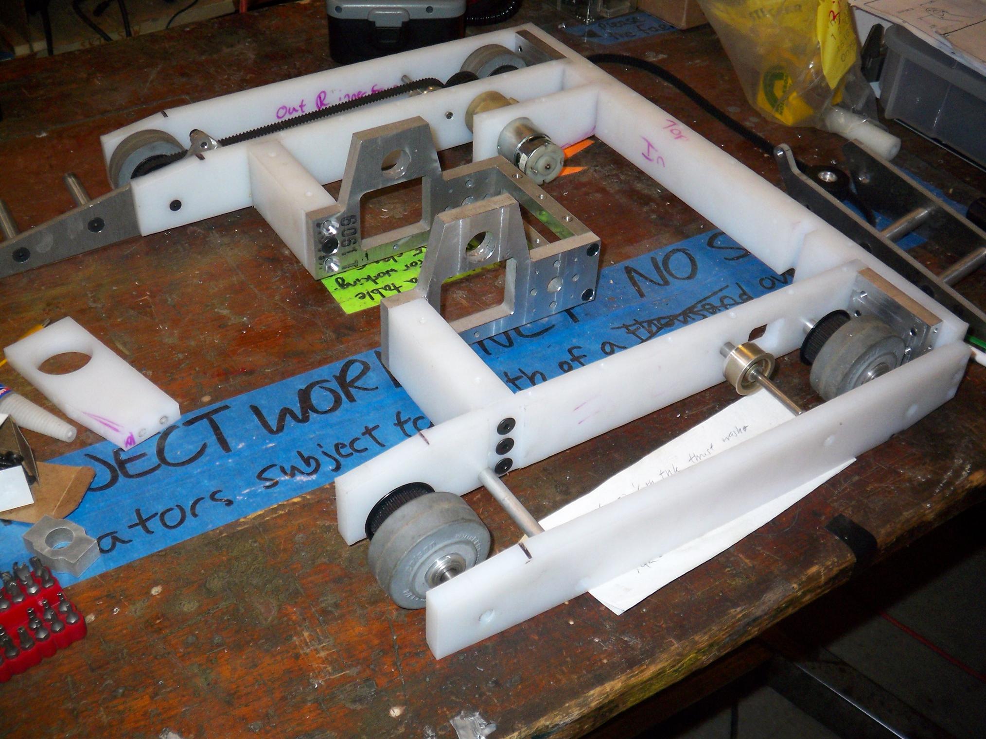
While I was waiting on some people to finish welding in the machine area, I finished out the drivetrain on both sides by mounting the motors and adding belt tensioners. To dismantle the drivetrain easily, I only have to release the large tensioning roller, freeing up enough teeth to slide the wheels off.
There’s enough tension in the belts to not slip on the motor pulley under constant (hold-wheel-down-on-table) load, but only a drive test will reveal the true performance.
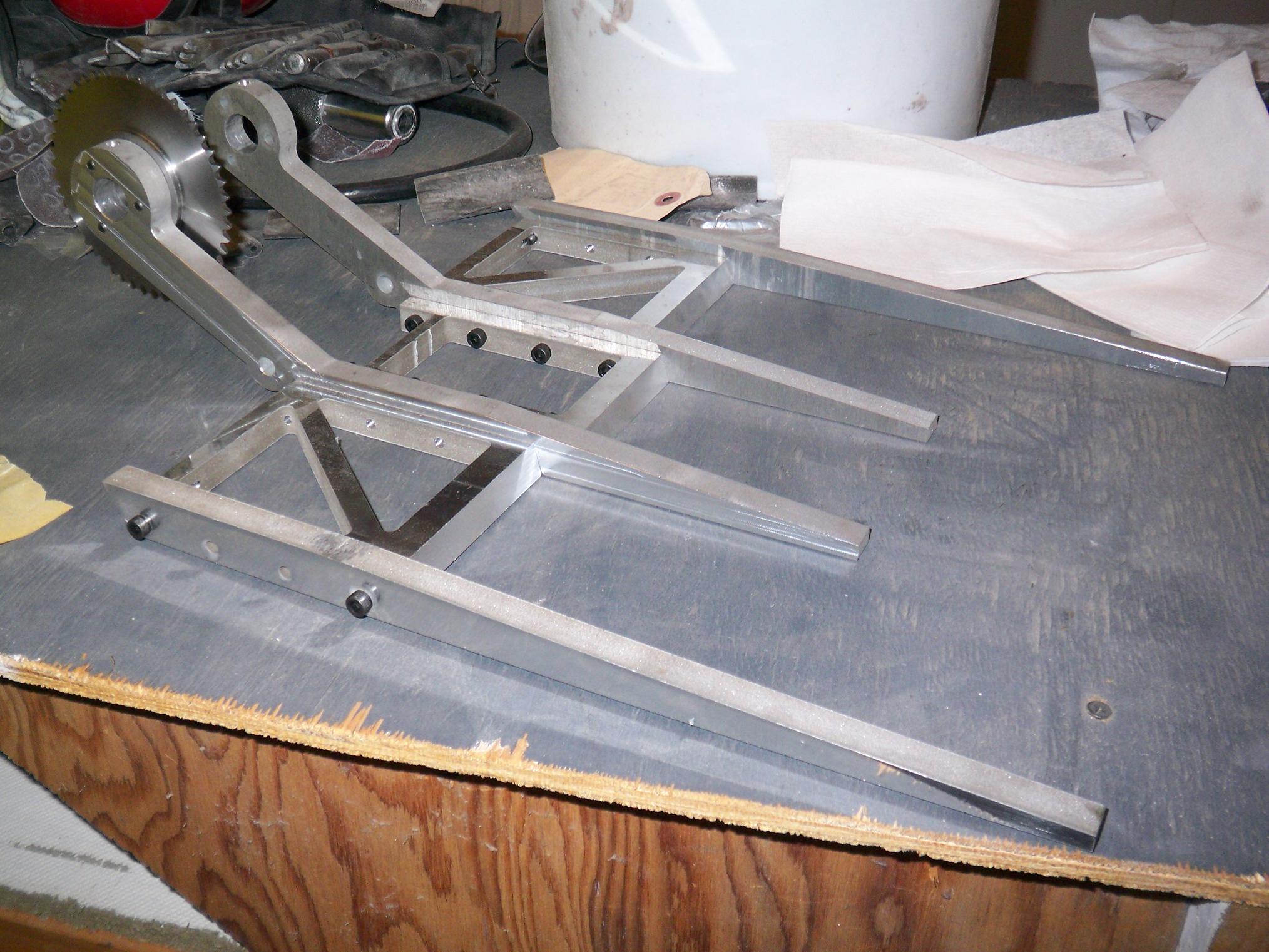
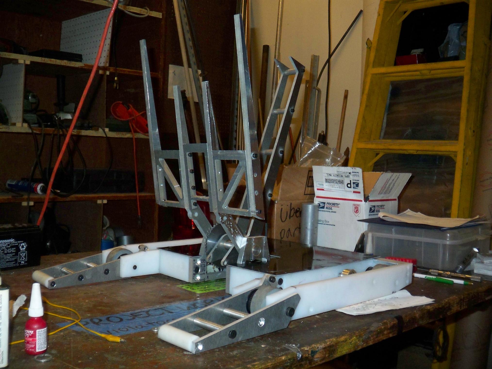
It’s ALMOST THERE!