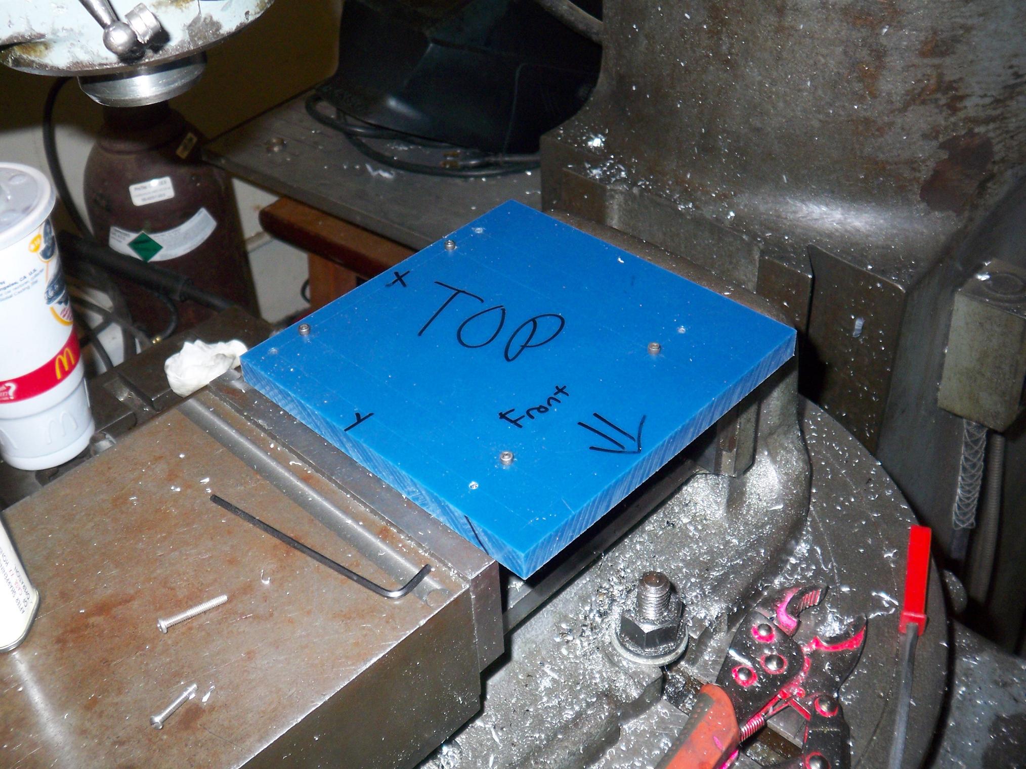
Work continues on PQ2 today with initial construction of drivetrain parts and the finishing of the frame. I woke up bright and early at 3PM and headed to the hardware store to get more body screws for Pop Quiz (and a handful of 4-40s for the fixture), as well as a 1/8″ Dremel spiral bit. It was a little sketchy as an 1/8″ endmill, but UHMW is soft enough for it to work.
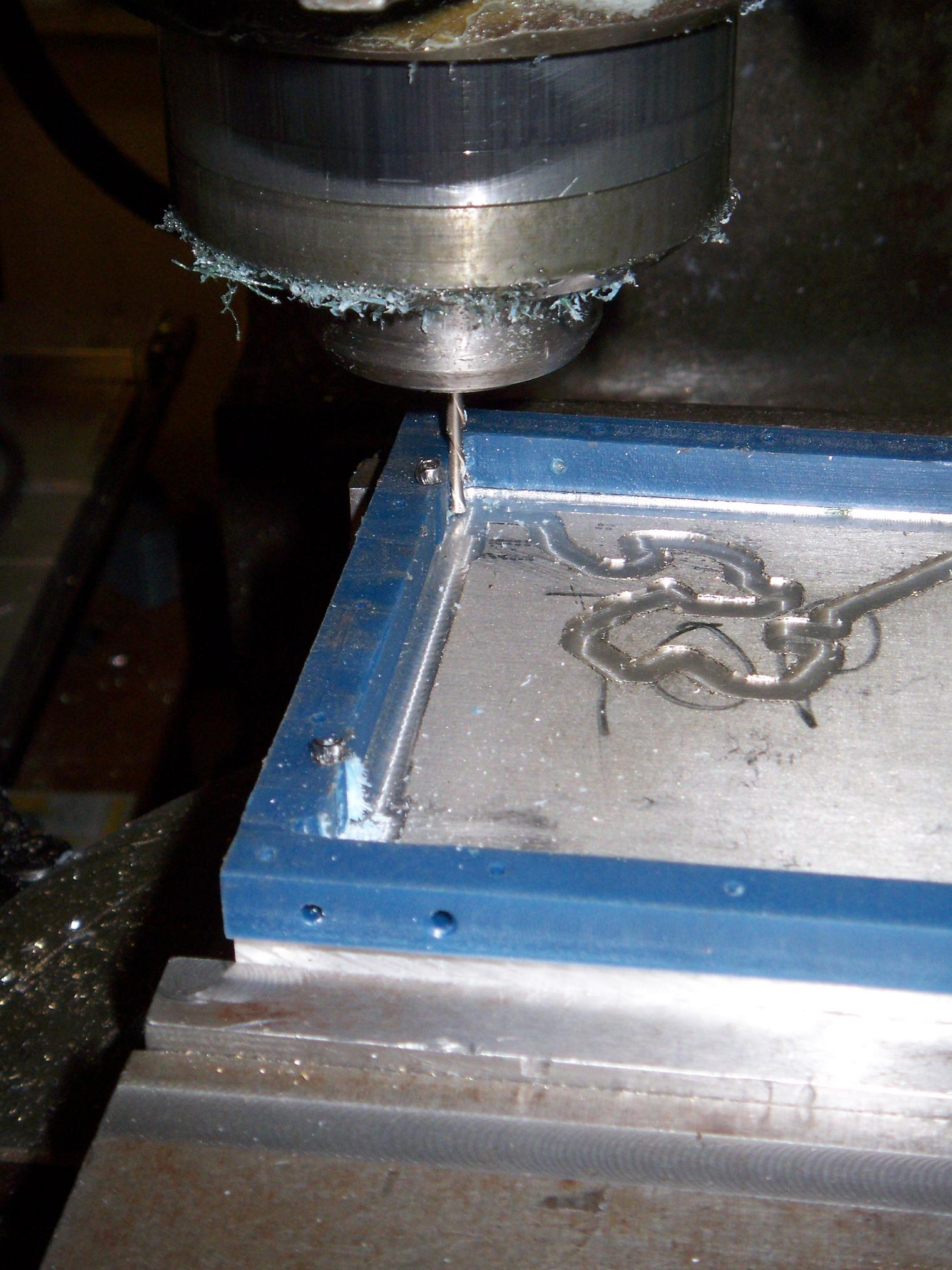
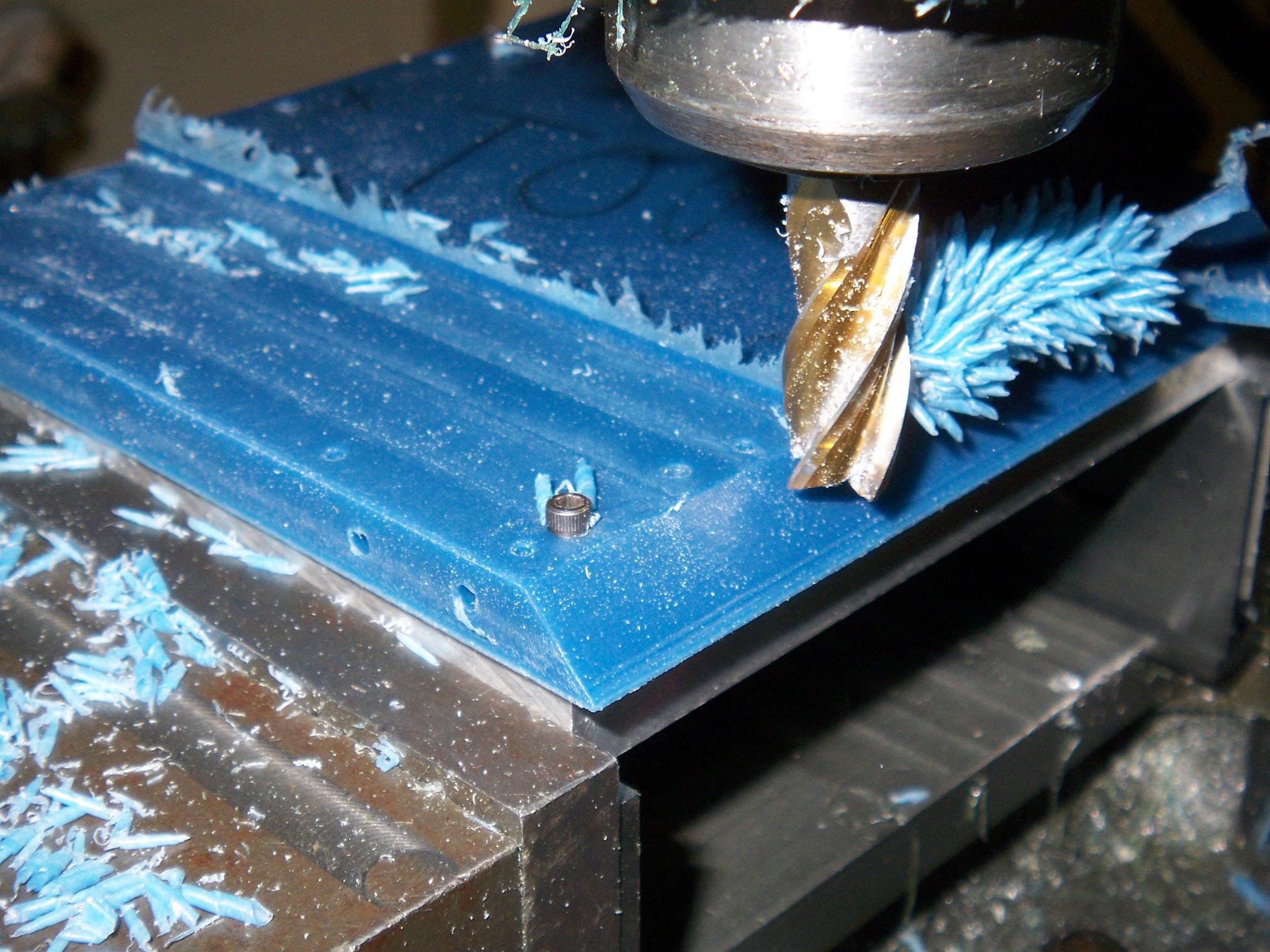
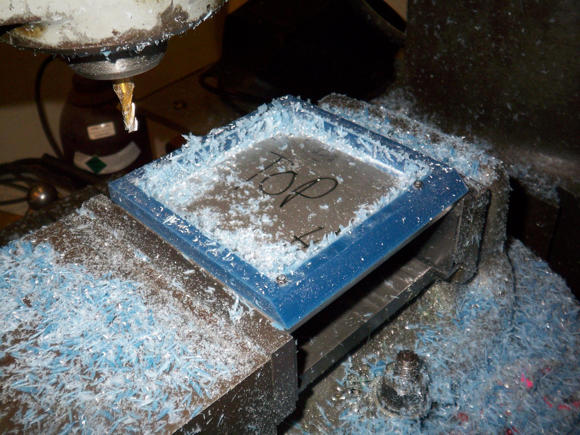
And off we go. Full bore on the spindle, about 2700 RPM, is still way too slow for something this small, so I fed very slowly. I Dremelmilled the four unoccupied slots first, moved all the fixture screws to those, then finished the rest. No telling how much my zeroes were screwed by playing around with fixture screws, but it’s not enough for me to care.
It turns out I milled a bit short on the left side yesterday, so I had to shave off an additional 1/16″ using the Dremelmill. Should have taken the extra 15 seconds to switch to a real endmill, as the finish imparted by the Dremelmill was less than spectacular.
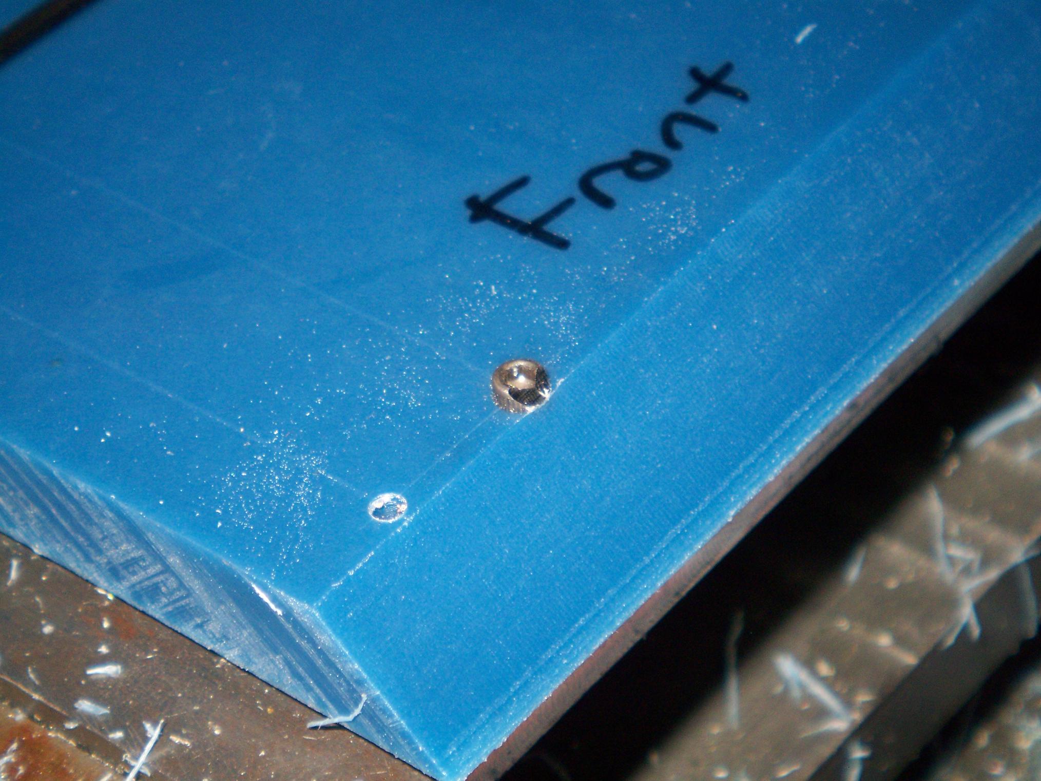
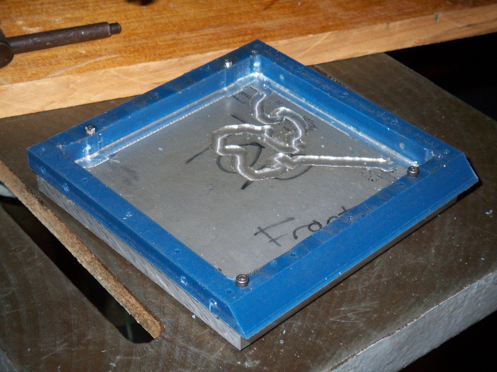
After the slots were milled, it was time to drill the front holes. This involved angling the mill head 45 degrees and projecting all my measurements to a 45 degree angled surface. Other than having to remember that all X-directions were √2 times more than what I think they are, it went smoothly.
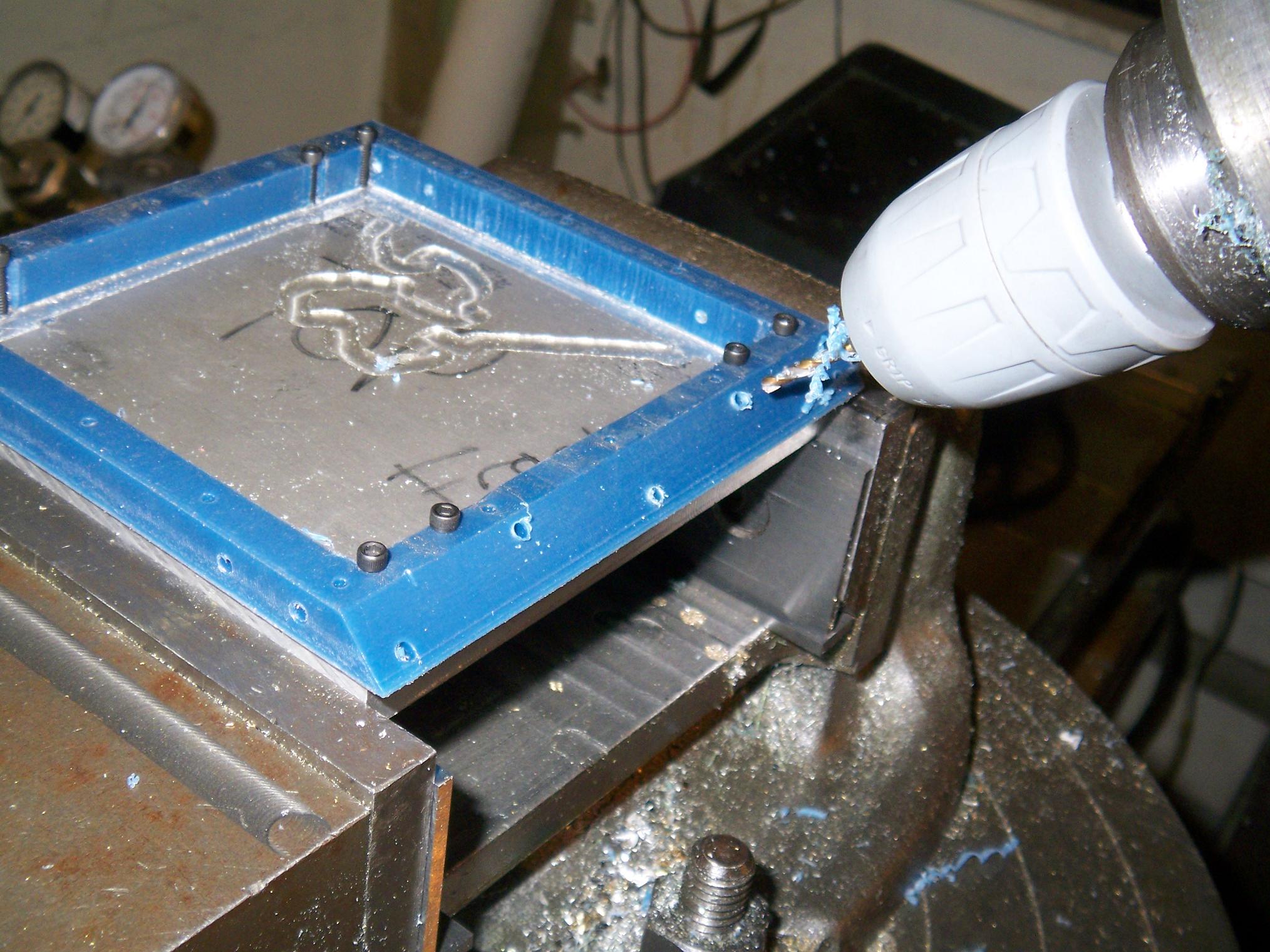
Done. I did accidentally drill too deep and deflected the bit on the aluminum fixture on one hole, but it doesn’t ruin anything.
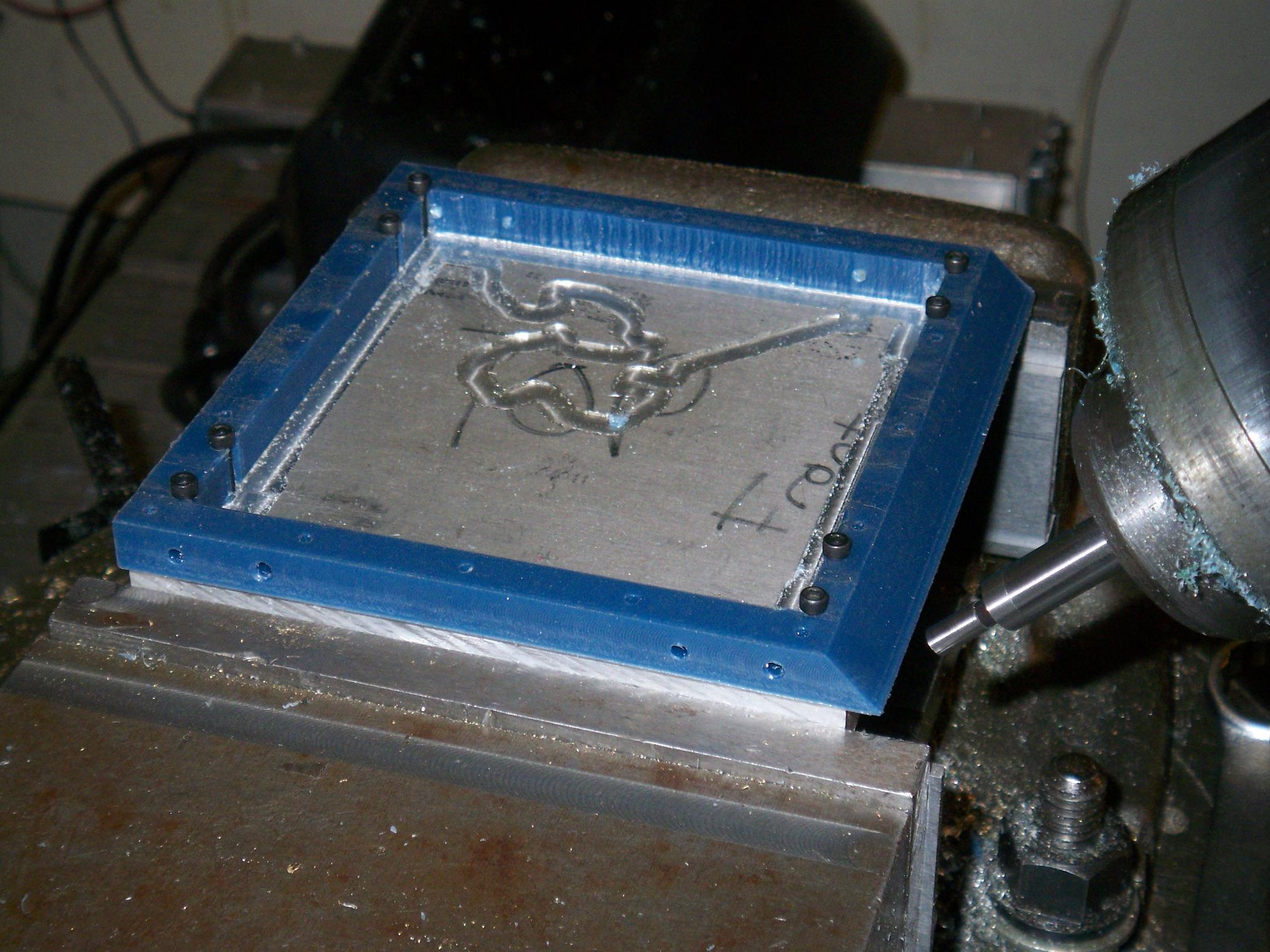
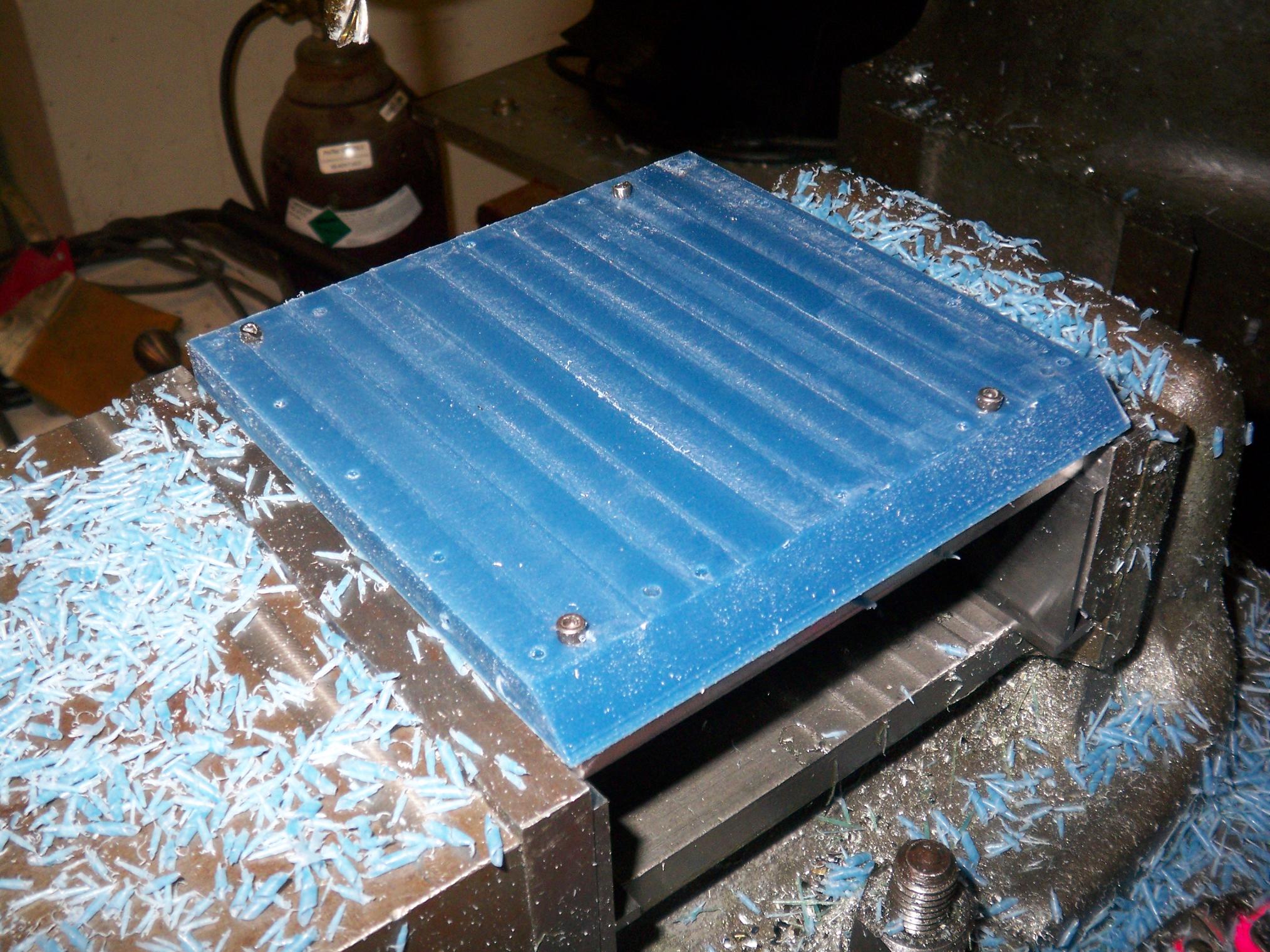
Finished frame. Overall, not too bad for playing around with the fixture as I was working, not using real endmills for finishing, and UHMW being the amorphous jelly-like material that it is.
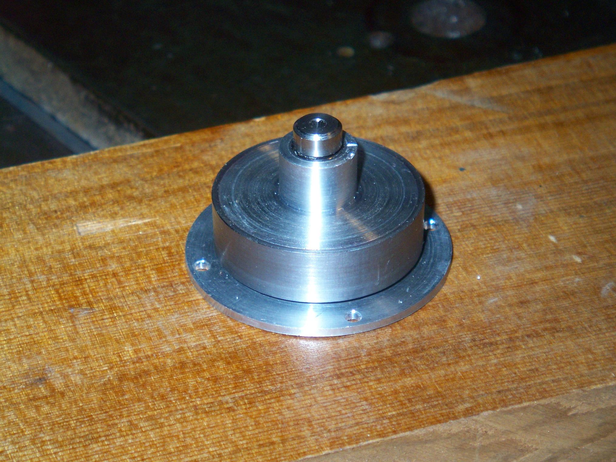
While the mill was still warm, I rebored the motor can to accept the bearings. A .375″ endmill made for a very nice “Loctite Finish” hole which the bearings pressed into.
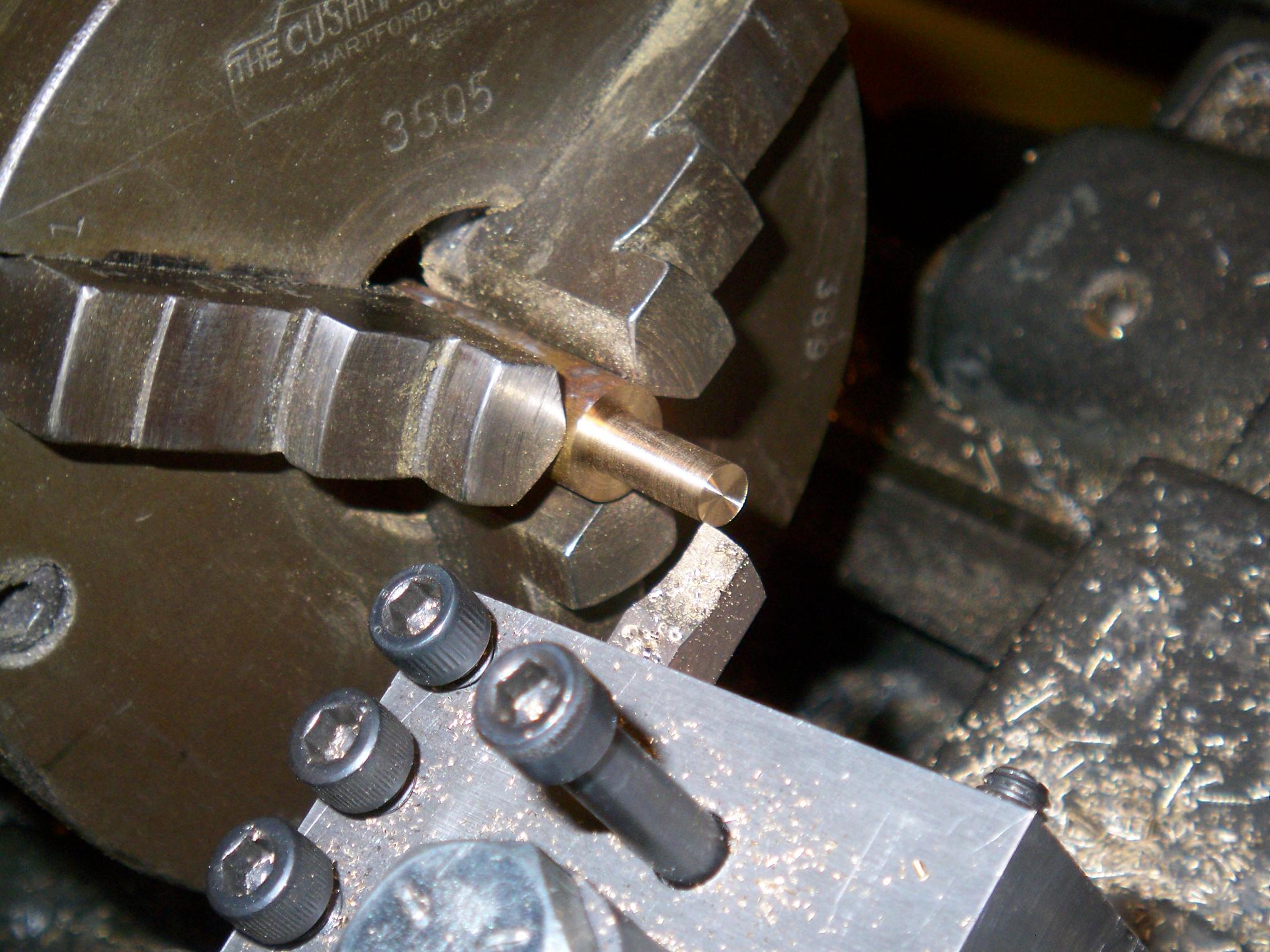
Time to see if I can actually make the drive pods or not. The drive hubs are made from little rounds of brass. Brass is a wonderful substance, as it falls away with the lightest poke of the tool… and I could take off the entire excess amount on a single pass.
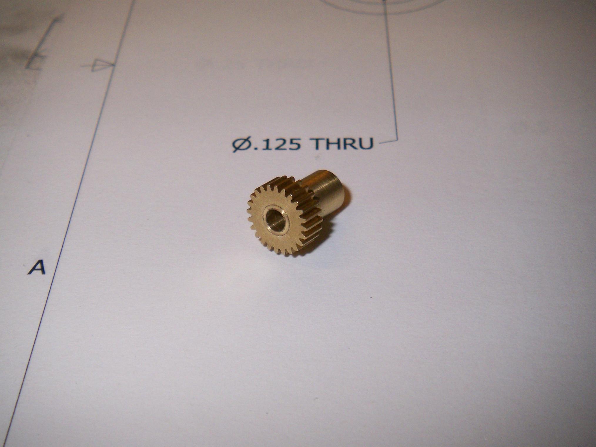
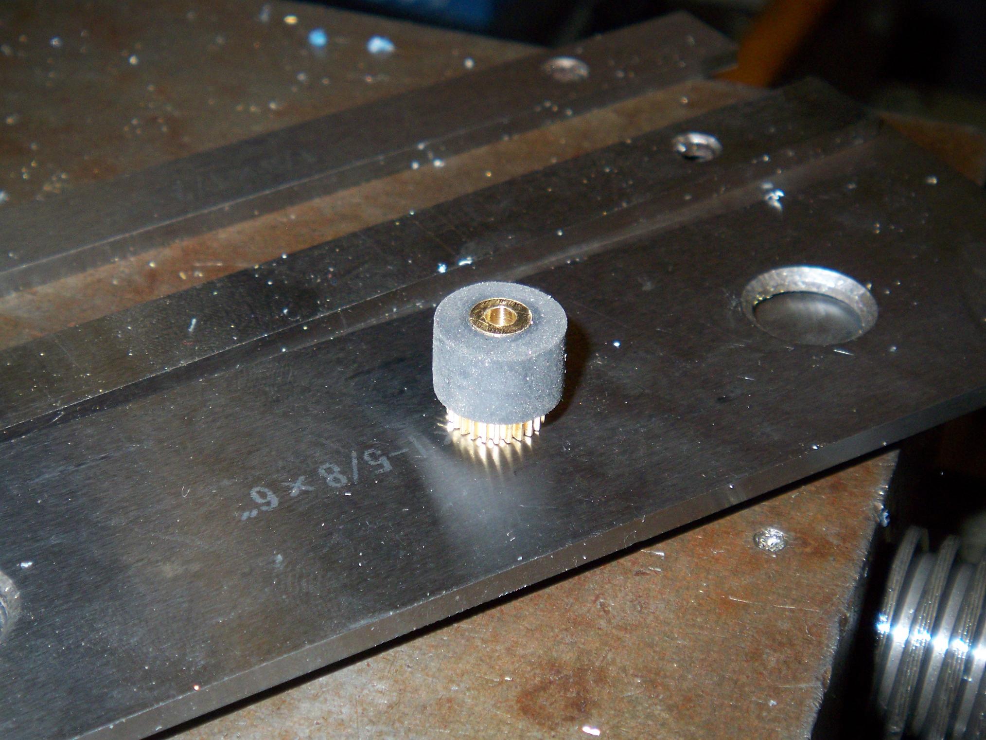
A finished drive hub! I drilled the gear with a #14 drill, which, at .182 diameter, is a nice press fit onto the .1875″ shoulder on the hub. The rest of the hub is .25″ in diameter. The bore is 1/8″, and will ride on a Convenient Section of CD-Drive Read Head Guide Rodâ„¢, which is a polished length of 1/8″ diameter hardened steel.
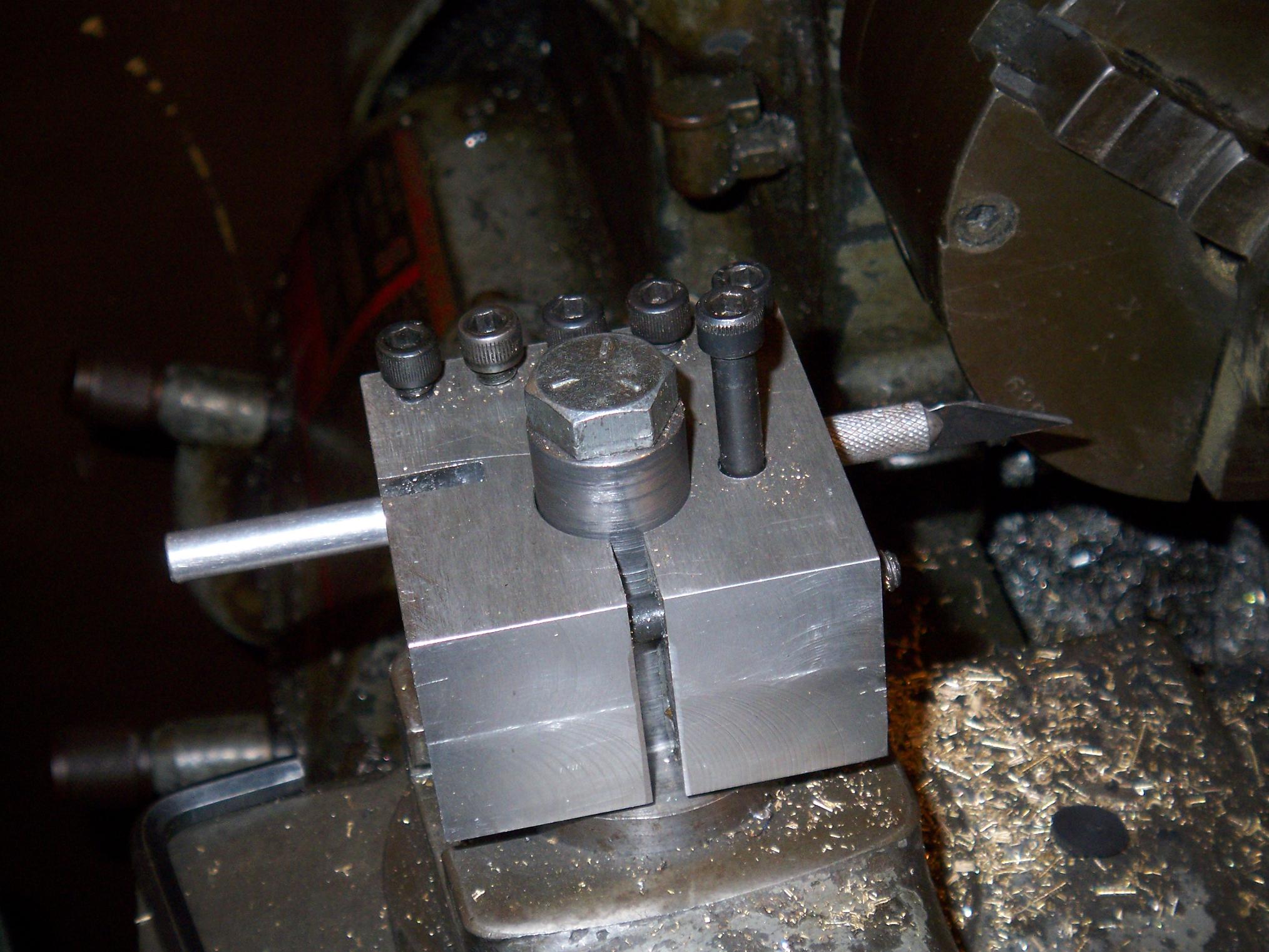
Now THIS is tool abuse. Yes, that’s an X-acto knife shoved onto the toolpost. What else would I do if I wanted to slit a soft rubber rod at a precise length?
Each Pop Quiz wheel is a half inch round of rubber with a .25″ bore, cut off at 5/16″ long.
A completed drive wheel. A 1/4″ drill bit would make a much-smaller-than-1/4″ hole in the rubber, which means I had to cram the wheel on. This is better than having to glue it down or something, and also makes the wheel easy to change.
With the 3 foot section of rubber I ordered, I could make a shitton of little wheels. The rubber used is 50A durometer “Santoprene”, which was cheap at McMaster.
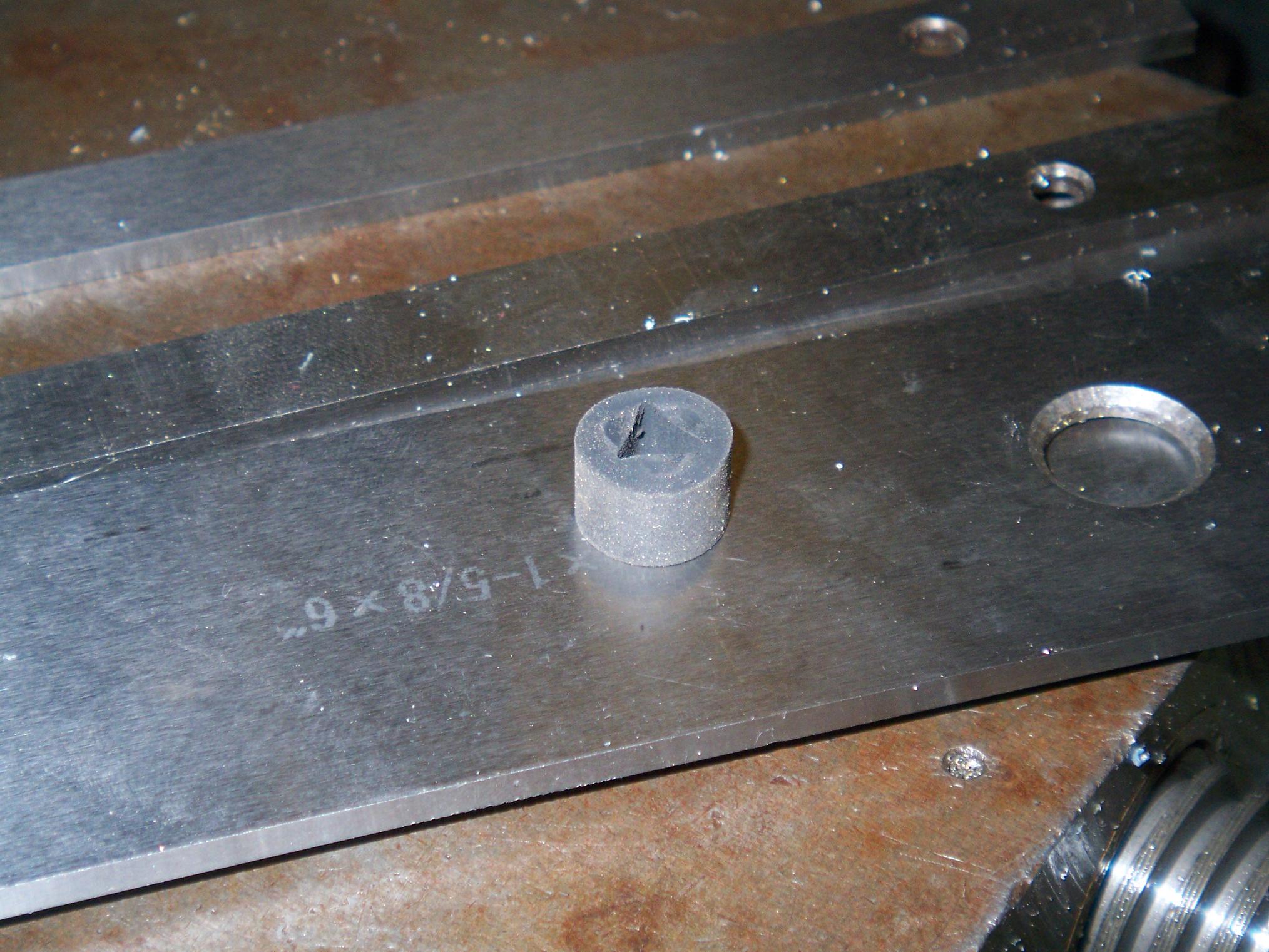
How do you drill a triangular hole?
This is what happenes when you squish rubber rod in a lathe chuck a little too far, then drill through it. The compressed material springs back and makes a neato shape.
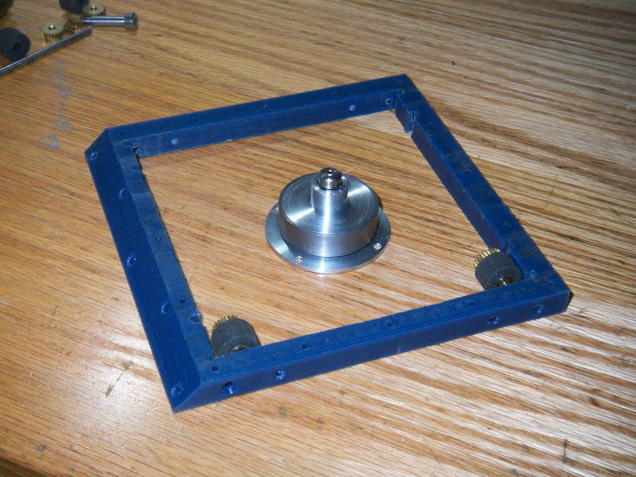
State of the bot as of June 1st. I went ahead and did two drive wheels before running out of brass rod. The motor just needs winding work now, and the frame is complete.
I ordered a carbon fiber sheet and the micro receiver from RobotMarketPlace. I need to get ahold of a 1/16″ to .093″ (or thereabouts) sheet of titanium to cut the blade out, and have been stalking EBay for proper candidates. Other than that, Pop Quiz 2 is on schedule with a projected mid-June completion date.
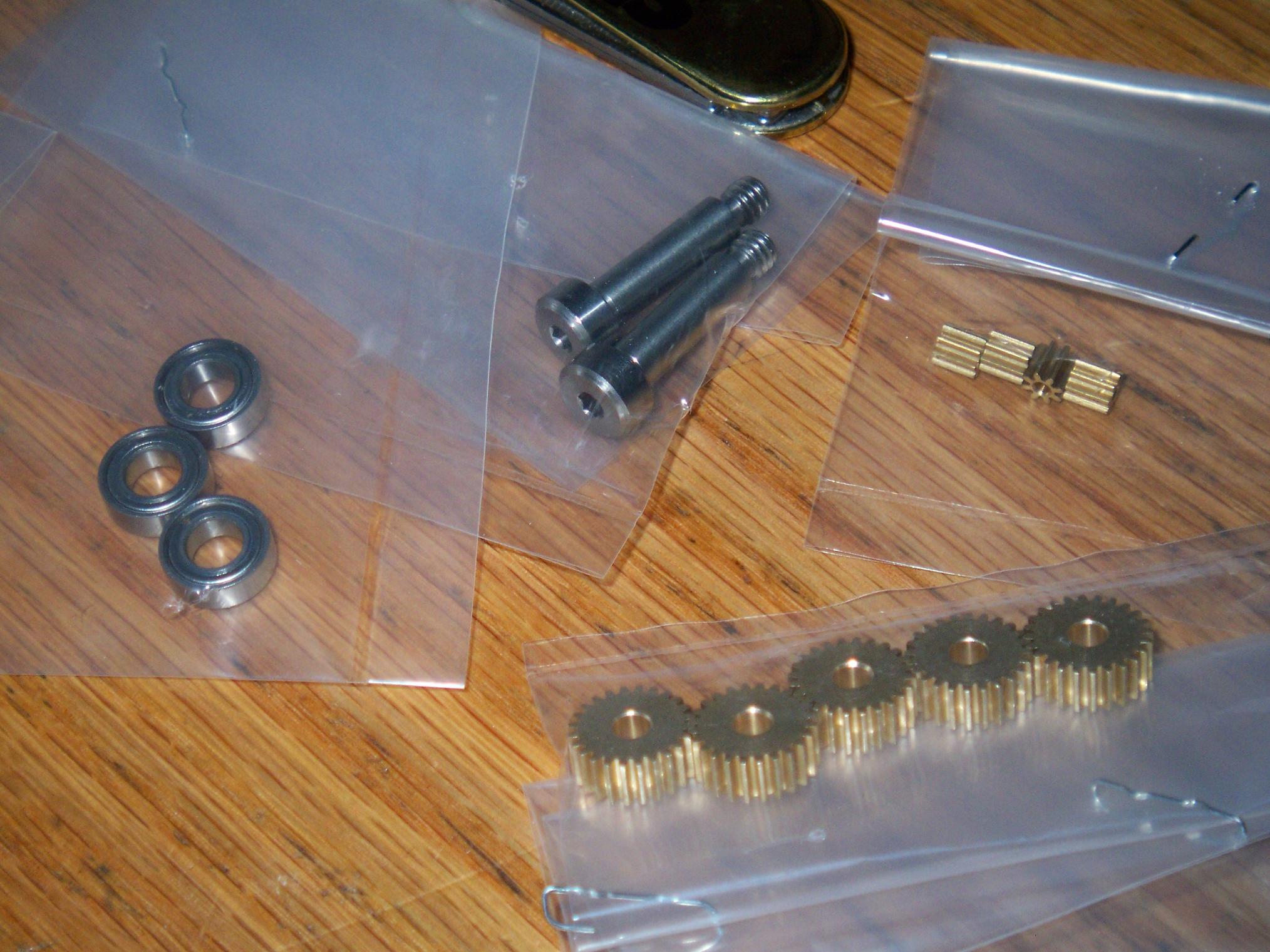
I have begun parts-gathering for Ãœberclocker, and made a McMaster order for all the random-ass bushings, shoulder screws, and other odd hardware I can’t scrounge. This somehow totalled up to be over $50 in random-ass bushings, shoulder screws, and odd hardware. Great Robot Jesus.
Bot On…wards!


