Winter is literally coming. As time goes on, my ability to work on vans decreases greatly both for lack of daylight and lack of inside matters. In preparation for overwintering now two vanbabies, I decided to make some repairs and mods that were becoming more necessary (or more necessary, if you get what I mean…). I like keeping my machinery in good functioning state, and Mikuvan was beginning to feel a little like a daily junker more and more. Meanwhile, Vantruck had some lingering bugs I wanted to address before my hands freeze off holding a wrench.
mikuvan
The most important thing was making sure Mikuvan could still pass its incipient Massachusetts state inspection. You see, since the day I got it running in 2013, the exhaust has been slowly shortening itself piece by piece. Recall that one of the earliest bits of mechanical work I did was to rebuild the catalytic converter flange. A year and some later, a part of the exhaust pipe broke apart, which I had a mechanic repair while it was on a lift already for a brake fluid change and rear drums inspection.

That was 2015. About a year to the day, before Dragon Con 2016, it breaks upstream of that repair. I threw together this patch in my classic weeaboo-redneck-engineer fashion

No beer cans here, only top quality RAMUNE BOTTLES. Three layers of them.
Several months later, that broke off, so I trashed the whole section from the bottle-hack back and replaced it with a 90-degree downwards bend with an exhaust tip on it, hanging on to the remaining muffler stub.
Well guess that, that broke the fuck off earlier this year, likely during the Detroit Maker Faire trip. I didn’t notice. I didn’t even care. It can rest in eternal pain and suffering somewhere on the side of the 401 in Ontario.
I just ran with the stumpy pipe out of the muffler which terminated well under the cabin, sounding vaguely like a ricer fart cannon but offering me nothing except exhaust slowly seeping into the cabin when I was at a stop or accelerated hard.
With the inspection date coming up, I had to do something.
Ah, good old New England Organic Loctite. It occurs naturally, regenerating from any exposed worthwhile metal in its vicinity. In the winter, it feeds off the gazillion tons of salt poured on the road and blossoms each spring.
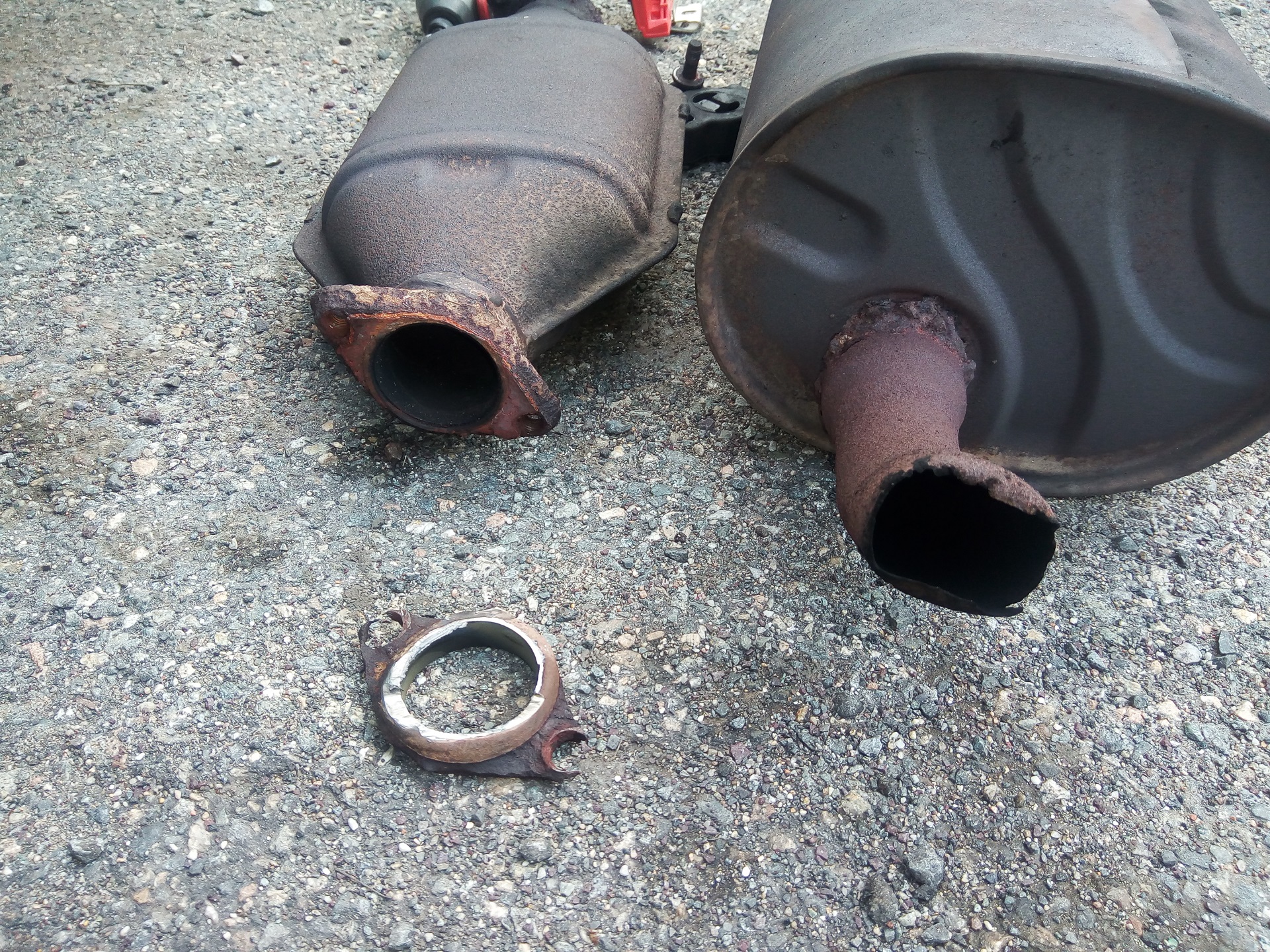
I’d watched the catalytic converter slowly get smaller and smaller over time – even the new gasket I put on it quickly became one with the material. I actually dumped PB Blaster on this flange connection while it was still hot – that was quite exciting. It then took several seconds of impact wrench before I was able to free the converter bolts. Frankly, I was amazed they were removable at all.
Since Mikuvan is emissions-exempt in Massachusetts, I elected to not buy a new catalytic converter and just latch right onto the downpipe stub.
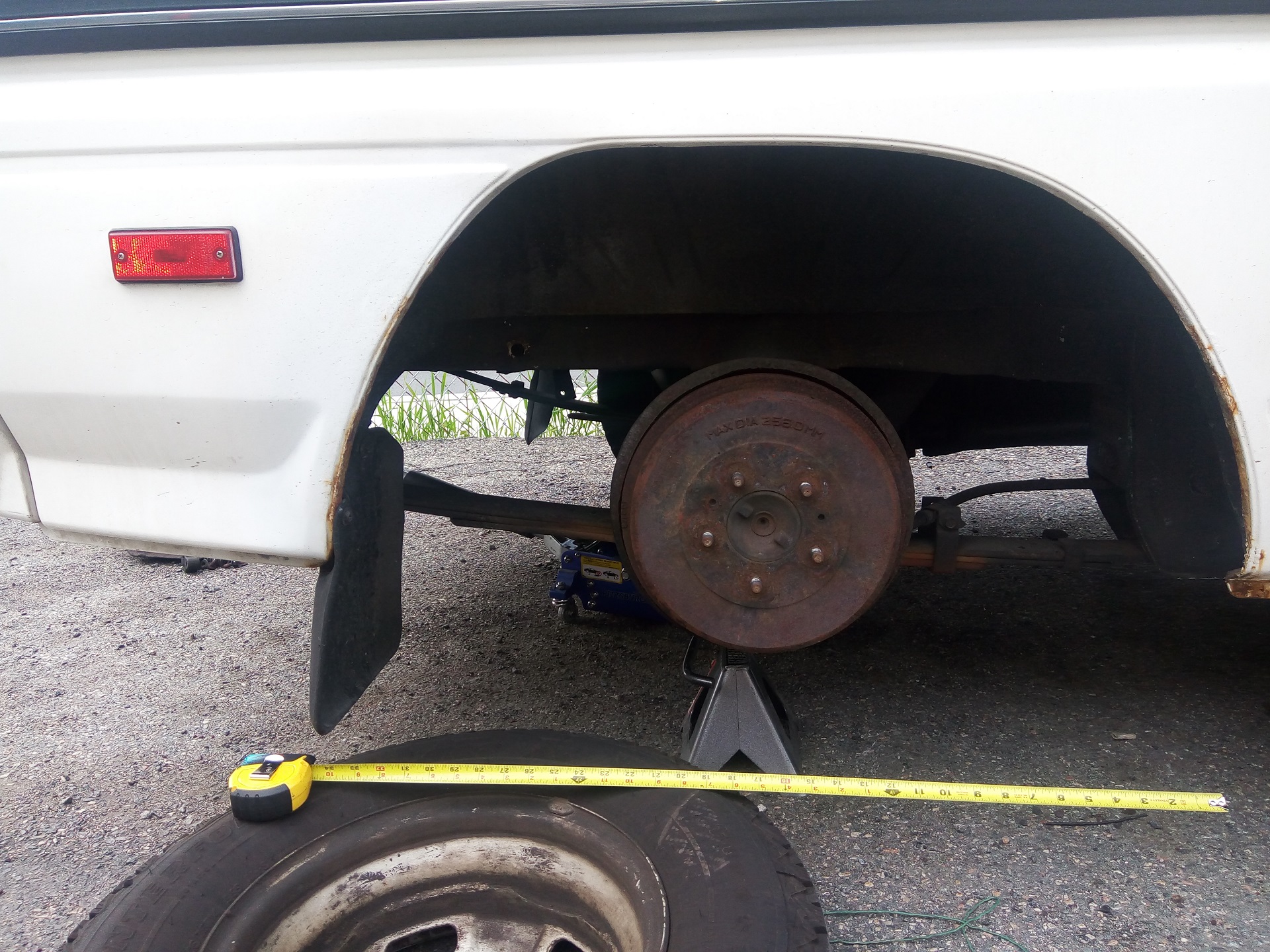
Time to measure up the exhaust path. I needed to clear the rear axle and end up at roughly the correct length to still put a muffler on. I decided to rear-mount the replacement muffler (which was also already rotted out at the bottom, so it wasn’t doing much muffling for a year or two at least) instead of mounting forward of the rear axle like it was before.

And two trips to Pep Boys later, I have all the ingredients! Several lengths of pipe, a flexible coupler, several rubber-mounting hanging straps, and a bunch of tubing adapters. All that is needed to get the right dimensions is an angle grinder!
What, you thought I was going to weld this shit together? Mandrel bends? Mitered joints? Nah. Clamps and impact wrench all the way.
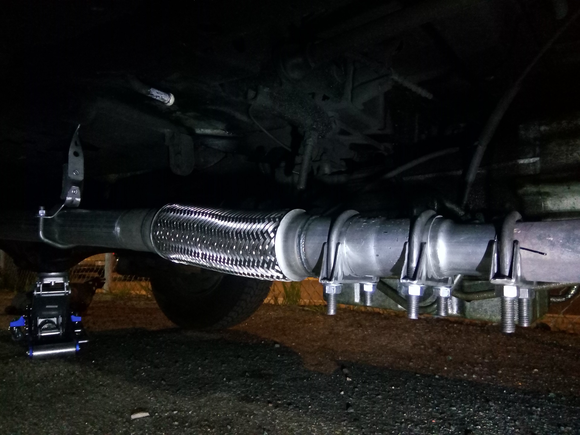
It’s nighttime in this photo because I ran into issues with the downpipe stub – it was some odd metric size of course, and there was no adapter which fit cleanly either inside or outside. I ended up using a 1-7/8″ OD adapter slit and shoved into the downpipe stub, which had a matching slit to let it expand a little. It was then a dance to get the other end of that adapter (2″) adapted to 2.25″ for the remaining pipe. All of the new pipe is 2.25″.
Yeah, the slit is a built-in exhaust leak. Whatever, it’s past the oxygen sensor. Maybe if I feel enterprising I’ll TIG weld it shut (and ONLY it) later.
This section has a flexible coupling in it since the catalytic converter’s output also did, and I wanted to keep the same constraint architecture. The length of solid pipe from here back is hung at both ends while the flexible coupling goes from the adapter salad to it. Should I be required to reinstall a converter in the future, like moving to an emissions-strict area where they don’t just go by OBD-II diagnostics, I should be able to stuff one back in here.
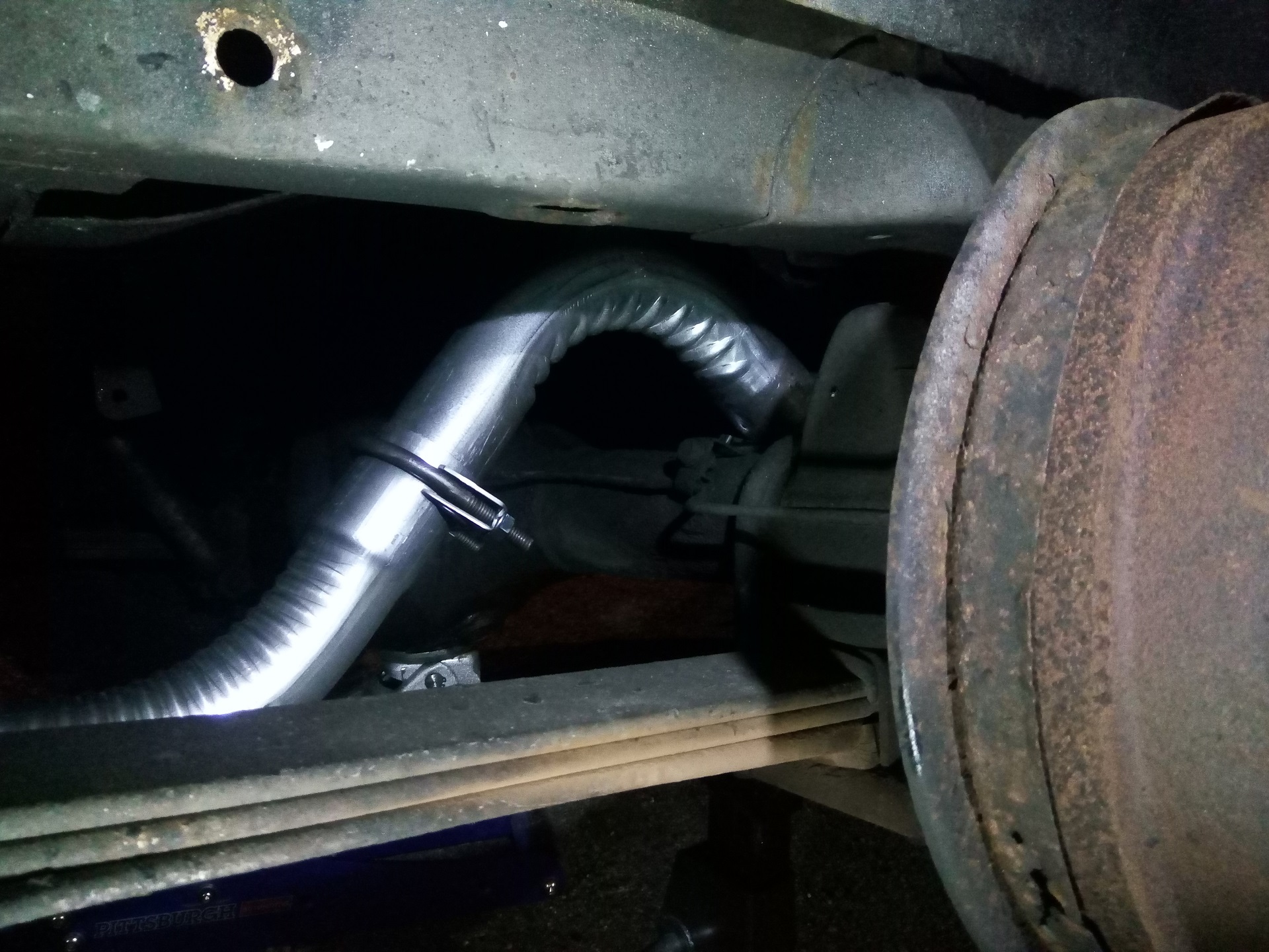
Compared to the… exhausting… dance up front, doing the up-and-over was quite easy and enjoyable.

I decided to be cheeky and go for a SPORT MUFFLER instead of an OEM style one. What, you wanted to sound like a sports car all these year, Mikuvan. Here’s your chance.
This is a Cherry Bomb “Turbo” multi-chambered muffler, distinct from Cherry Bomb’s usual fiberglass packed ones. I don’t have a turbo. I don’t care. It was $28.99 on sale at Pep Boys, and a little of on-the-spot research told me that glass-packs would definitely bring out the ricer fart cannon sound, but would foul up quickly due to the engine consuming oil. Given that, I was better off with a chambered type.
Anyways, this first attempt made it hang a little too low, so I had to cut the strap and bolt it in closer to the trailer hitch.

The final position. It’s not actually tilted much in real life, by the way – the perspective of this photo is a little strange, since Mikuvan’s rear lower quarter panels curve upwards and the trailer hitch is actually a little tilted upwards also.
So, how do I like the end result?
i regret everything in my life
Okay, the ricer sound was funny for about 24 hours. Between 1000-1500 rpm and 2500-3000 rpm, it seems to resonate the cabin, resulting in a constant mooing sound, a persistent droning. Guess which RPM bands get used the most during gentle city and highway cruising!?
Mikuvan sounds like it has 75 more horsepower than it actually does, which is a 75% improvement. It DOES have more low-end jumpiness, like the second after mashing it from a stoplight. Additionally, the power available past 3500 RPM improved noticeably – previously, trying to throttle past 4,000 didn’t do me much good, and it felt like the engine just hits a wall, but my gas mileage the week after took a complete dive as I was redlining everywhere all the time.
I think this is less due to a sport muffler than just installing the new system as 2.25″ pipe instead of the stock 1-7/8″ (50mm?) pipe for its majority length. I didn’t bother to check if the 0-60 changed. That’s not the point. The answer is still yes.
Realistically, I might toss an OEM style muffler on there after winter passes. One Dragon Con and Franklin Institute with the Persistent Moo was fairly sufficient, thank you.
Anyways, let’s move onto the more important part of van maintenance: blinkenlights. I replaced almost all of the small marker and dashboard lights with LEDs back in 2014. A few of them had begun dying, including somewhat important things like the previously chastised oil pressure warning light. That’s maybe a little important.
inexpensive chinese van lighting 3: the reckoning
I decided that enough time had passed to do a scan of the market again, so I hopped on good ol’ Amazon Prime. The market structure™ is very different now – in 2013 and 2014, a lot more of the LED widget vendors were China based. Nowadays, they (or their underlings) all have Prime fulfillment or US-based shipping.

What I noticed is a rise in these purely PCB-based LED units in small (T10, T5, 194, etc.) sizes. I originally bought several styles which were plastic former incandescent lamp shells containing discrete LEDs with formed leads. Those actually didn’t work very well in the end. The LEDs had no heat sinking and tended to burn out or dim quickly, and the formed leads pretending to be T-series shaped were flimsy.
Also, a lot of the LED clusters were unnecessarily bright, containing 5-10 devices. It’s a marker light, bruh, not a camera flash. The ones I found contained 3 or 4 little LED chips only and seemed to have a lot more PCB copper area relative to their size. An example captured from Amazon is bove.
I was curious about one more thing: Most of these products now claim to have “CANBUS error-free” features. After doing a little sleuthing, I discovered that it’s a New Car Problem (a.k.a I don’t care) of the LED bulbs drawing so little current that the ECU/Body control module will throw an error saying you have a bulb broken.
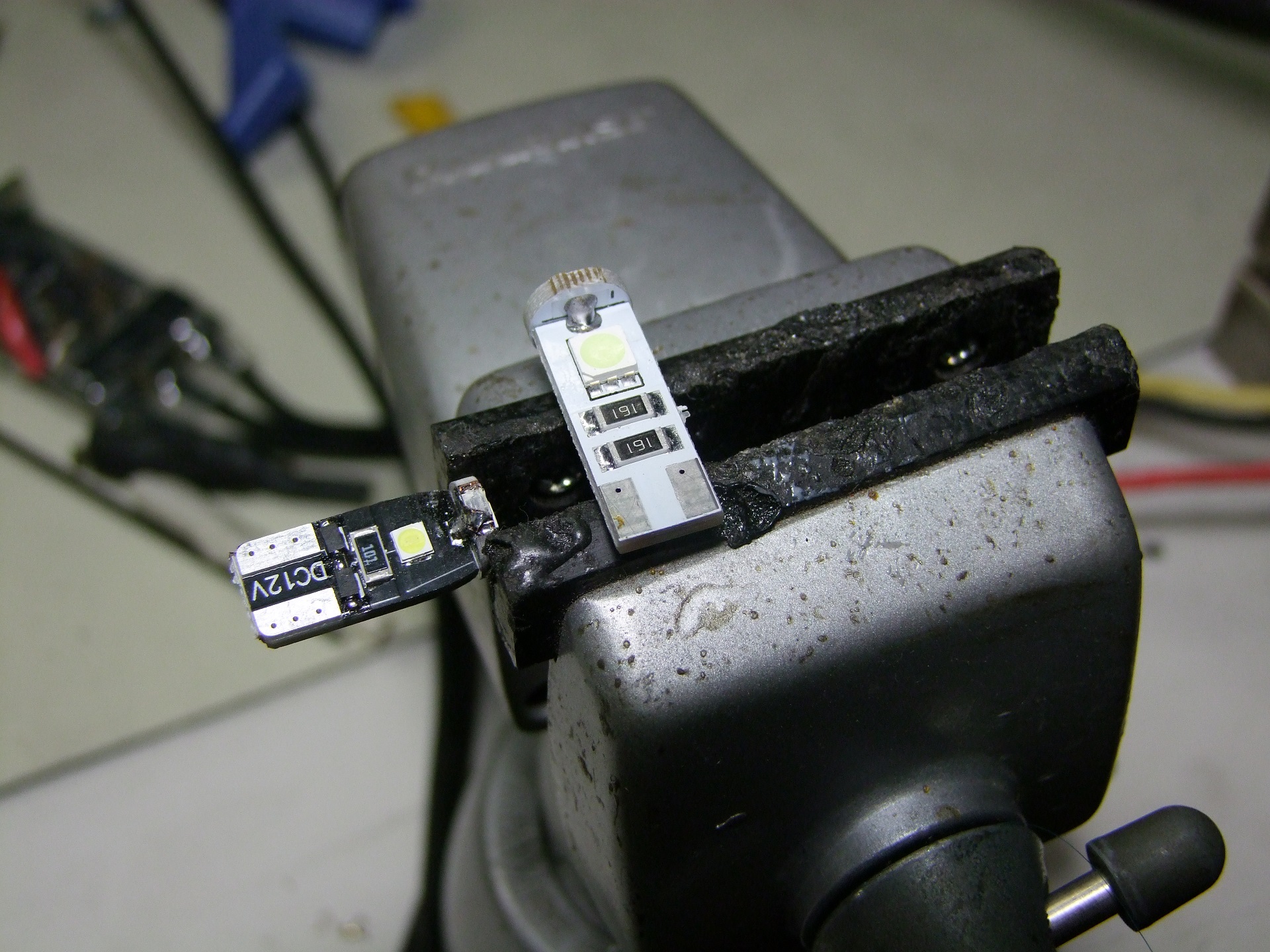
….so here is how the enterprising Chinese widget makers solve it. They drop a big power resistor across the input. To make it draw more current.
This is utter bullshit. Do not EVER buy a “CANBUS Error Free” LED bulb. If your car is new enough to complain, it’s new enough that you shouldn’t be putting questionable aftermarket glowy things on it anyway. Get an old shitcan like these were meant for. Preferably a van. I like vans.
Here is what the typically 100-to-200 ohm power resistor does: It heats up.
It heats enough to some times desolder itself.
It’s also right next to the LEDs, so they heat up even more and even faster than if they were over-rated and over-driven. I burned one out on 14.0v after like 3 minutes of it just sitting on my desk. It was drawing 0.2 amps until the end – that’s 3 W of power heating up an object which weighs nothing. I think I know why so many of these products have bad Amazon reviews: sadly, people don’t know better.
I desoldered each and every “CANBUS resistor” on each and every one of the 50 white, miku blue, red, and amber LEDs I got. This did not take long, since I had a reflow cannon, but I was peeved to discover that my worst fears regarding inexpensive Chinese van accessories had come true again.
The white T10 units drew 0.05 amps after I was done. That’s more than enough.

The end result is real pretty though.
I changed the master illumination to the “ice blue” LEDs which is really clever marketing speak for my favorite color, Miku Blue. I also restored all of the small indicators to pure white units so their original colors were back.
That’s enough for silly lighting. It’s still the case that if you want actually reliable LED units, you should still stick with a retail brand name like Sylvania or Philips. They’re going to be pricier, but unless you also have a reflow heat gun and a night to burn and are at least a little obessive like me, just get them.
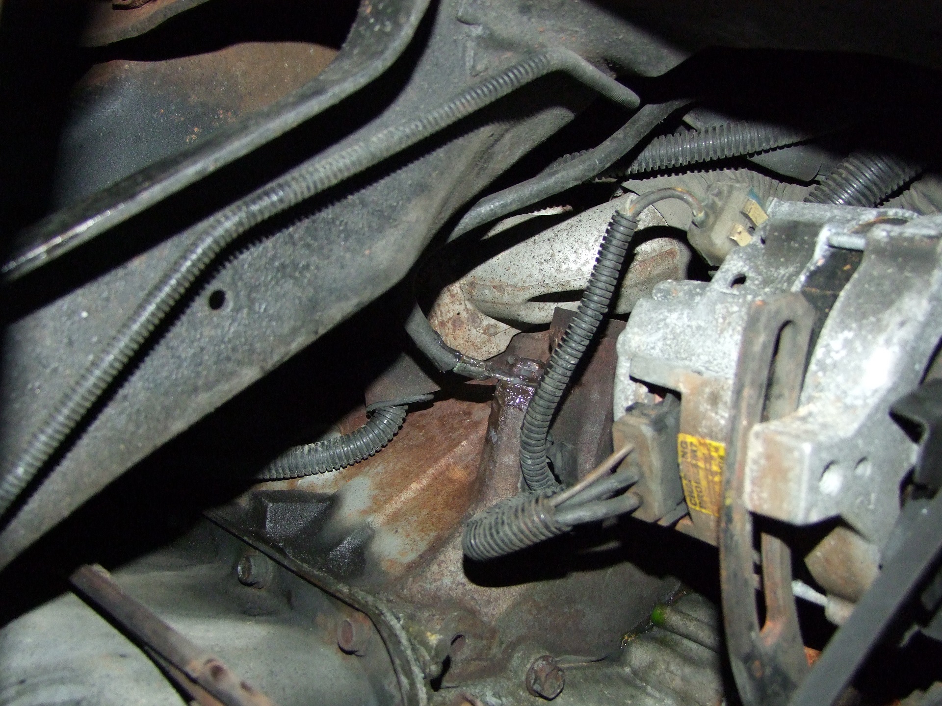
More recently, I tackled a more reasonable silly old van problem of a broken sensor wire. While doing the fall-to-winter oil change, I noticed a loose wire.
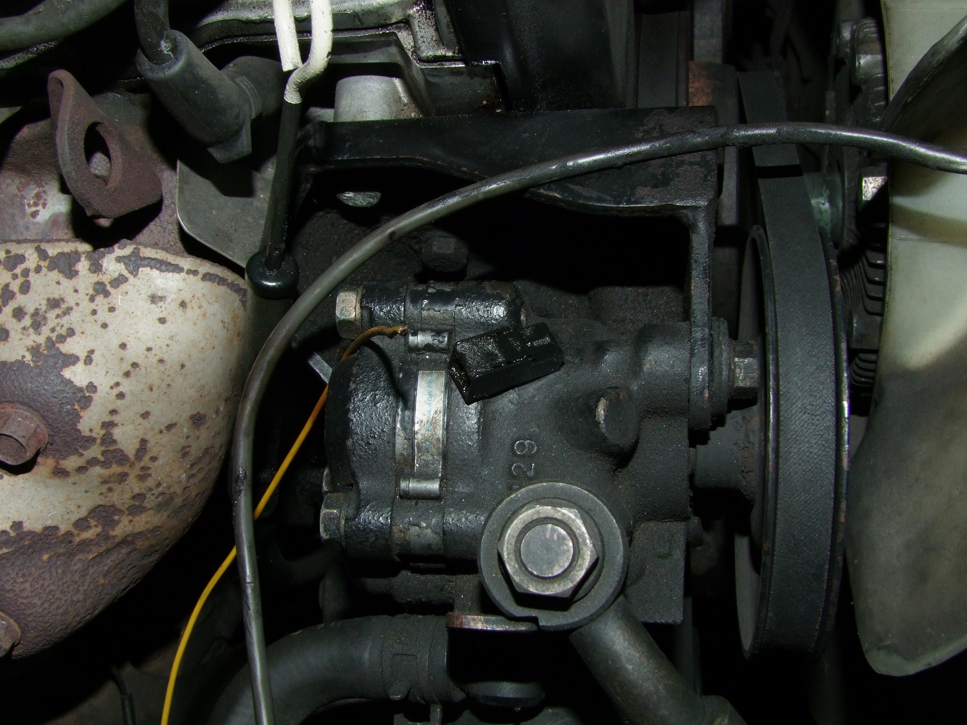
This used to go to the oil pressure sensor (what is with the oil pressure sensor and light as a recurring theme here…) which is located on the bottom of the engine. Heat and oil had stiffened the old PVC-insulated wire until it just broke off inside the connector.
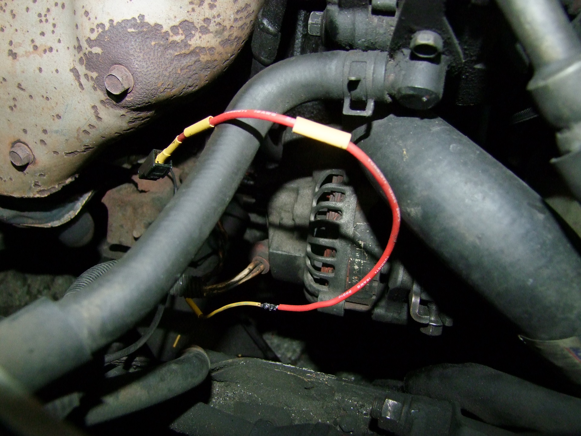
This wasn’t too epic of a fix. I replaced the original wire with a length of silicone-insulated noodly robot wire, up to where it enters the harness and was still quite flexible. This shows the joint and repaired connector before I sleeved it over with heat-shrink tubing and tucked it back into the wiring loom.
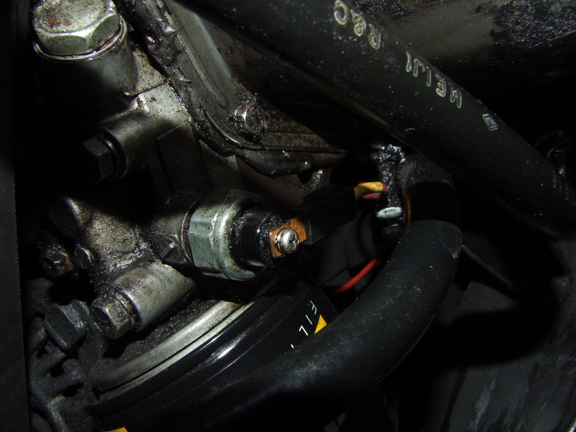
Back in place we go! Excuse the grunge. That is Mikuvan leaking the correct amount of oil my self-applying undercoating system.

I additionally performed some mercy maintenance on the left side. My original body repair on the left rocker panel corners fell off earlier this year. I was kind of expecting this, since I was never able to get the holes in the front (behind the front wheel) fixed and so that repair only trapped water, causing it to fail eventually.
I decided it was better to just leave the lower panel holes open but seal-coat them inside and out. This strategy had been working (and continues to work) for the two holes forward of each wheel, which I coated in Eastwood Goo back in 2014 thoroughly.
So out comes the wirebrushes, in wheel and tooth form. I wire-brushed off all outstanding surface rust first, and reached into the panel holes to manually wire brush off the loose rust inside. Additionally, while I had it up on ramps, I used my slide hammer to try and pull down the damaged lower rocker panel and pinch weld. If you buy a derpy Japanese van, chances are someone’s tried to jack it up by the pinch welds and completely fucked over the metal in the area, I guarantee it. I only take Mikuvan to mechanics I have talked to and trust for this reason: I don’t trust anyone to know it can only be jacked by the frame. This area came rusty and bent upwards, and had only been deteriorating more. I couldn’t get it completely flat again, but it at least looks better than it was.
Prior to the application of Eastwood Goo, I touched up the paintwork right next to the fuel filler door and immediately in front of the rear wheel. The former had been slowly dissolving due to gasoline fumes and accidental overflows, and was turning the whole area dark and ratty looking as well as causing some of my original bodywork to start chipping off. If I had to point to one thing which crossed my “daily junker” threshold, it was this. I haven’t found a rattlecan product which can completely resist gasoline, so this area will only become ratty again until Mikuvan gets a real paint job.
After the color and clear coat were vaguely dry – as dry as they could get in 40-something degrees, I drew a big fat line with the Eastwood Goo both on the outside here as well as the opposite side, using the extendo-straw to go well into the interstitial space of the panels on both sides.
Essentially I’m just preserving this area from further deterioration. Should I decide that dropping several thousand dollars on a full restoration and repaint is worth it in the future, I will source this body panel either domestically from the southwest/California, or internationally since this generation of Mitsubishi van is still (somehow) in production in various developing countries. Otherwise, an experienced body shop would just strip it all to bare metal anyway. Should I embark on an electrification project, I’ll likely start anew with a donor van in better condition from the same areas (since I assume that if I’m going ahead with cutting up Teslas and Nissan Leafs, that I’m well off enough to have my own garage and lift!)
So that’s Mikuvan’s history for the past 2-3 months. Interspersed with all of this was of course the comparative 800-lb gorilla and relatively white elephant of….
vantruck
Oh god why do I still own this device. It’s been a year, yet it still feels new and interesting.
As I had sampled a pile of LEDs again, one of the things I did immediately was to retrofit Vantruck too. The incandescent bulbs it came with have long darkened and were sort of miserable looking. The dashboard was so dim it was almost impossible to see even at night.
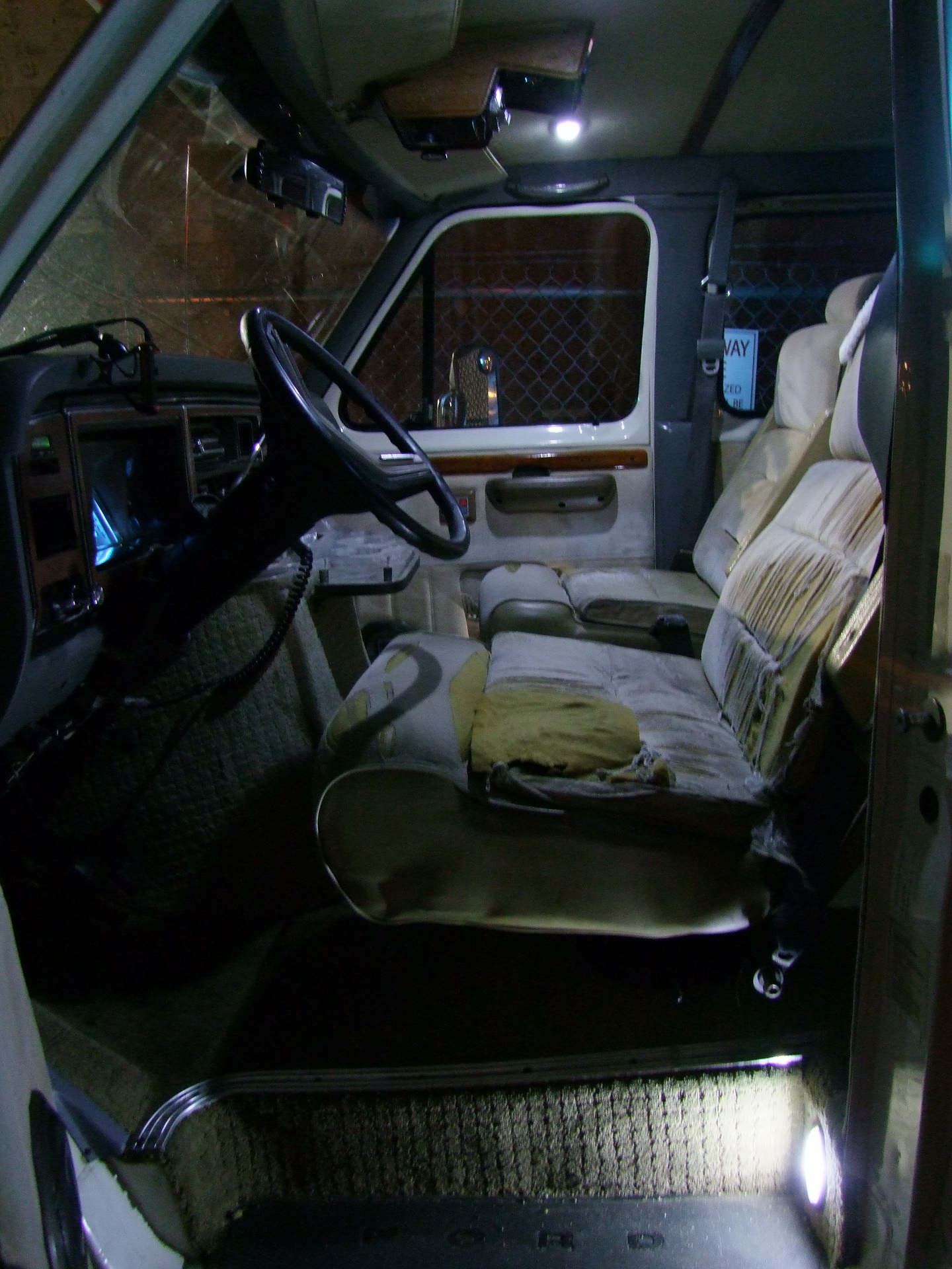
Well that’s no way to live! Luckily, it uses type 194 bulbs EVERYWHERE. Even the idiot lights. I had to buy another pack of T10/194 type LEDs to satisfy it. (Vantruck is the undisputed king of the phrase “I had to ____ another ____ to satisfy it”)

Naturally, all of the dash illumination went Miku Blue. This was also taken before its 77777th mile party, celebrated by Dane on the road to a Power Racing Series race. Without him realizing it. Hurray, Dane!
By the way, my friends have put more miles on this thing than I have. Since the fuel injection retrofit, it has somehow registered no less than three trips to the New York / New Jersey area and one to southwestern Massachusetts, plus the odd DUDE BRO CAN I BORROW YOUR TRUCK BRO moving trip around town.
I don’t feel bad at all. Buying gas is punishment enough for them.
Along with the interior lights, I also redid the running board lights and forward exterior marker lamps. They were….. you guessed it. 194 type bulbs. I changed the “I am a van” lights by the door handles to Miku Blue since I’m Mr. Vain. It turns out that the bed marker lights are a sealed non-replaceable type, but I can get new ones which are all LED. I haven’t done that yet. I didn’t do the roof lights either – they are fastened from underneath, meaning I’d have to take off the roof liner to access them, which I was not inclined to do.
Notice something else cool? Vantruck now also has LED headlights. They are the same type of unit I got for Mikuvan, except in the H6054 size. They are available in all manners of Chinesium – here’s one example. Just search H6054 LED and don’t buy the 15,000-LED cluster bombss or the fake projector types.
After the LED switchover, I noticed a particularly Vantrucky bug becoming much worse – the lights were flickering hard. LEDs have no thermal mass unlike incandescent filaments. Something was causing all of my lights to flicker, including the dashboard. When this kind of thing happens, there is generally one culprit: a bad ground connection. I dunno whose amazing idea it was to chassis-ground automotive electrical systems, but it’s horrible.
In conducting a test to verify the problem, I connected one end of a voltmeter to the negative battery terminal, and through an alligator clip of sufficient length, to various “grounds” of the electrical system, such as the negative pole of a headlight, the body metal right next to the dashboard where a bunch of grounds for switches and knobs come together, and right next to the battery on the alternator. With the engine running, I captured an incredible 1.2 to 1.5v between battery ground and most things. The worst was, as expected, to the dashboard and interfacing with the body lighting harness in that area. (The correct expectation range I found is usually no more than 50-100 millivolts, and the lower the better just from my electrical engineering intuitions)
Holy crap. Well that explains why the FiTech ECU screen always tended to read my battery voltage as 12.something or 13.something. I verified that from the alternator output to itself I was getting a pretty consistent 14 volts.
The culprit was right behind the alternator – that’s the engine block to battery negative ring lug. I don’t have before photos, but let’s call it “rather pitted and sad looking” and its attachment bolt entirely coated in rust.
My solution was just to epicly wire brush the bolt and the attachment face until they were shiny, and crimp a new terminal onto the 4-gauge cable which was still otherwise in reasonable shape. After retightening, I smeared dielectric grease around the entire setup.
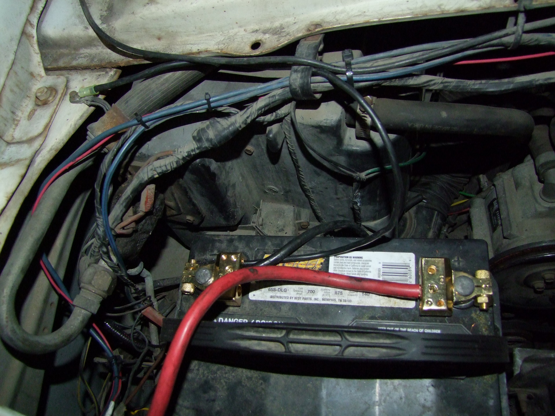
I decided at this point to also give the thing new battery terminals which I had purchased a while back but not installed. I furthermore gave the body a dedicated 10-gauge wire running from the attachment point where (as far as I can tell) the headlight and turn signal harness is grounded.
So I’m not sure if this is an Old Van Problem or is still present in newer vehicles, but it seems strange to me to ground everything to the body and frame yet only give the battery a cable to the engine block. Is the return current supposed to find its way back through to the engine block, jumping through things like bolts and bearings and chains and driveshafts? That just seems extra bad.
I mean, it’s clear there is enough metal contact for it to work for most everyone. Even Mikuvan only has 1 epic ground wire going to the battery from an anchor point on the engine block and nothing else that I can see. Unless I’m missing something, it seems like a dedicated ground wire for the body is really beneficial. It could be that in both cases, there is an actual connection somewhere else on the block to the body, but it’s buried so far in there I have not been able to find it.
Anyways, the moral of this story is wow, I didn’t know all of these lights could be so bright. The ECU display now reads very steady and the correct voltage – 14.4v right after starting and 13.6-13.8v idling when warm. The dashboard is almost comically bright and I had to turn it down with the dimmer for once. Cranking is much faster and less arduous. I should probably go inspect the status of the ground lug on Mikuvan at some point.
By the way, after resolving this issue, I completely reset the FiTech ECU and had it ‘relearn’ the fuel maps by driving around a bunch in mixed regimes. The stable and higher voltage power supply probably helps with a lot of things, so I gave it a chance to re-adapt. Regardless of any other changes behind the scenes, it definitely idles more stably now, so I experimented with leaning out all of the air-fuel ratio targets so it wouldn’t chug gasoline as hard – maybe a few percent less.
Well, over a long distance, that sure matters, because I’m going to a CAR SHOW!!!
the Jalopnik Car Show for Great Justice or Whatever
Delayed once due to being rained out and with the full force of Internet irony behind it, the Jalopnik car show was held the Sunday after Thanksgiving. This would be the first road trip that I myself will get to take in my own vantruck. It would also be the first car show that I actually signed up for. I’ve been to others, including smaller local ones. Everyone has to remember that I am not actually a “car guy”, just a “this one particular silly van” guy.
It was going to be 4 hours on a Sunday in Newark (uhh), which alone is too short of a stay for me to want to drive 55mph the whole way there and back. So I turned the weekend into a general New York City excursion.
With this thing.
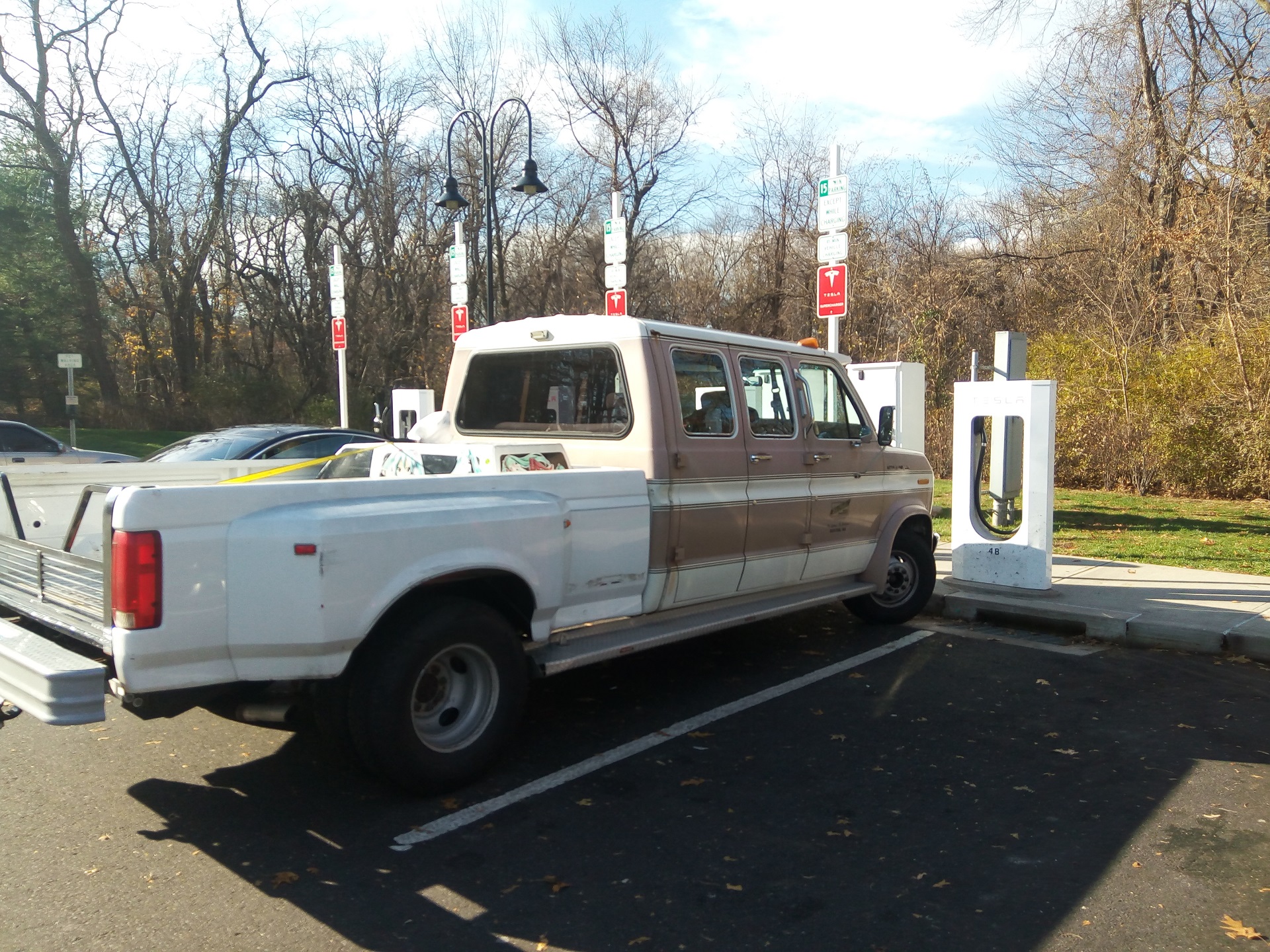
If there is some poetry in having a big-block V8-having 9-miles-a-gallon-getting emissions-exempted 21-foot long 65-tons of American Pride occupying a Tesla supercharger spot, I missed it for the funny photo opportunity.
The two Tesla drivers who came in and out while I was hanging around uploading this photo for peoples’ amusement didn’t say anything. Not to me, not out loud. They didn’t dare defy the embodiment of all that is America.

And here I am poking out of a parking spot in Flushing! I’m backed all the way up to the green wall. Actually, it’s pushing the green wall back a good 3 or 4 inches. I felt the contact, and kept shoving a little. Sorry, wall. Sorry, whatever was behind the wall.
So before getting here, I actually drove it straight into lower Manhattan and the Financial District/Battery Park area to try to find…. a location where I could take a photo of it with the Statue of Liberty in the background.
‘murica
Sadly, that part of Manhattan is too busy and blocked off for any of that to happen. Through friends, I was told that I’d have better luck in Jersey City or parts of Brooklyn. I decided that was out of scope for the day and retreated to Flushing to gorge myself on noodle products by performing a rolling Denial of Service attack on the Brooklyn-Queens Expressway.
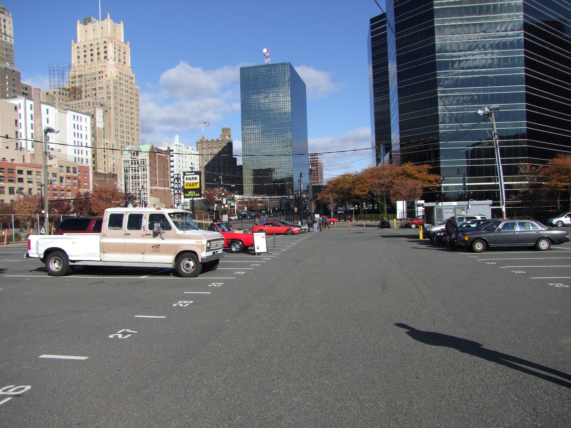
Bright and early the next day! They said to show up early. I assumed people were going to start lining up an hour before it starts, so I hustled out of Queens and got into Newark around 10:30. It turns out the organizers had barely even gotten there, so whew.
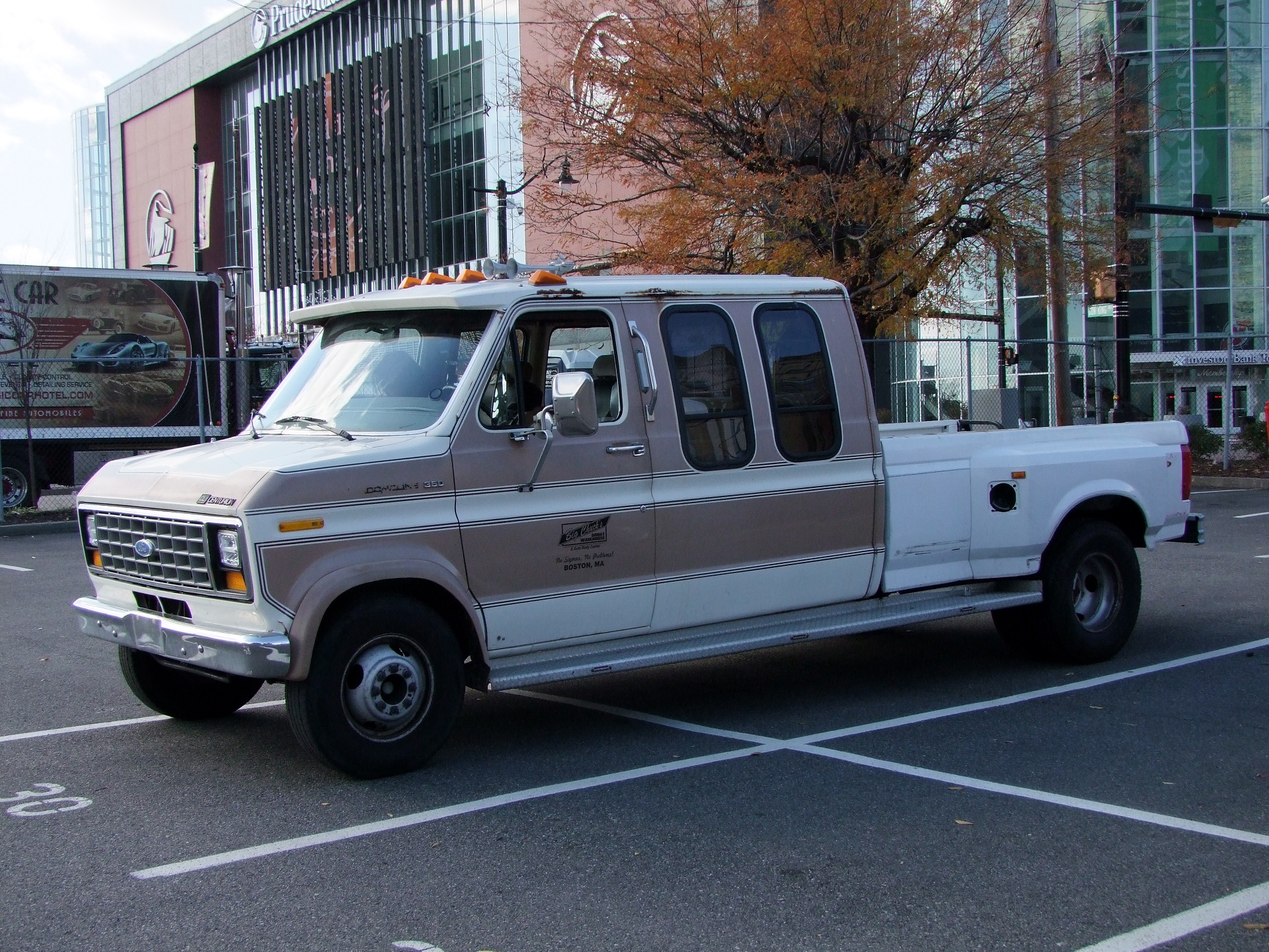
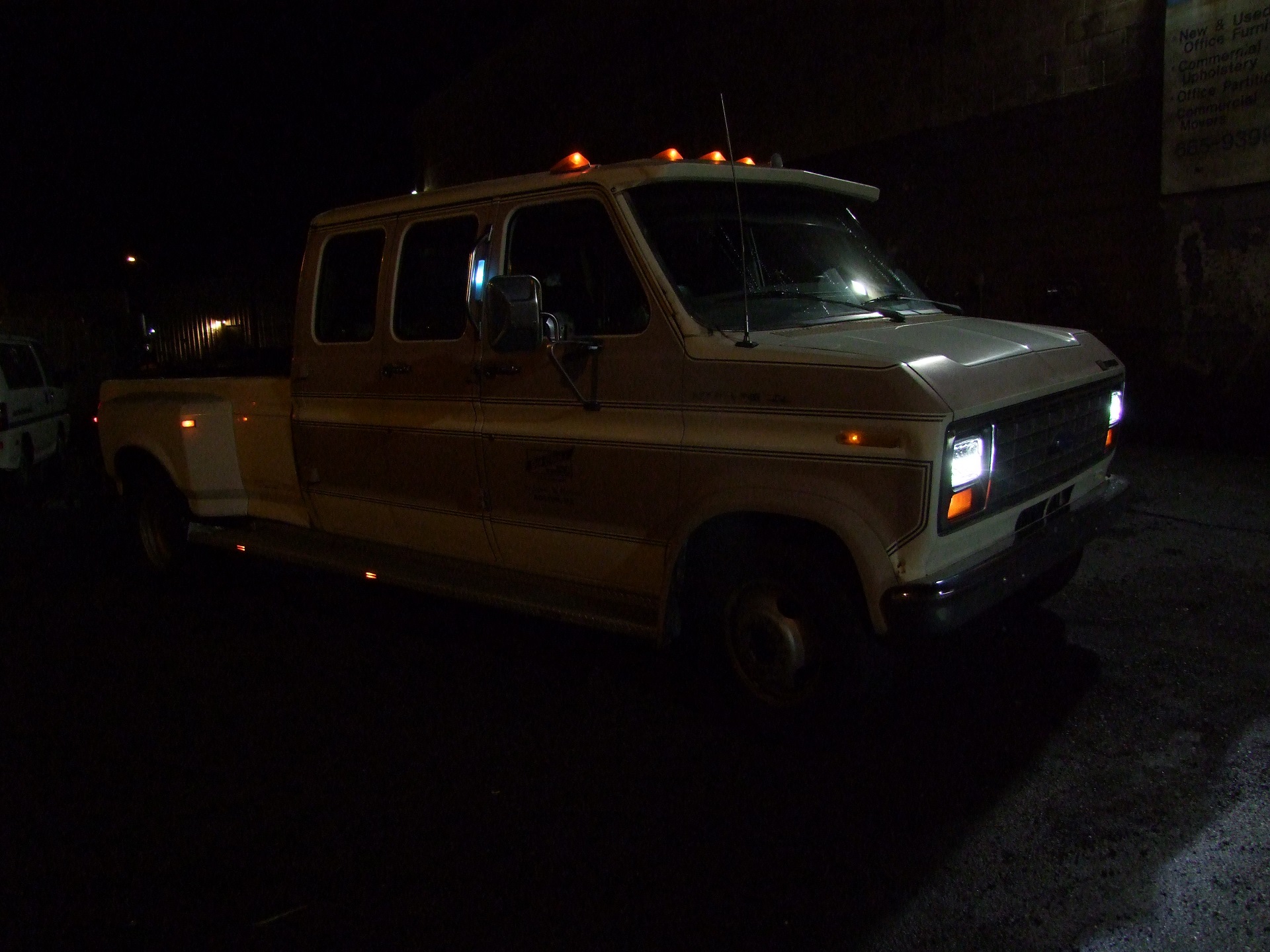
Well, at least now I have one clean and recent photo of Vantruck before everyone else showed up.

Hey! I brought Chibi-Mikuvan along for the ride, and it was extremely popular. I did some promotion of Power Racing Series, but only when asked.
Originally, I wanted to trailer Mikuvan down, but decided it was simply too much of a production for a 1 day event, and dealing with a now 40-foot long assemblage of vehicles in New York City was a little excessive. If Jalopnik chooses to do a weekend festival of shitboxes or something, I’d happily organize a carrier battle group rollout.
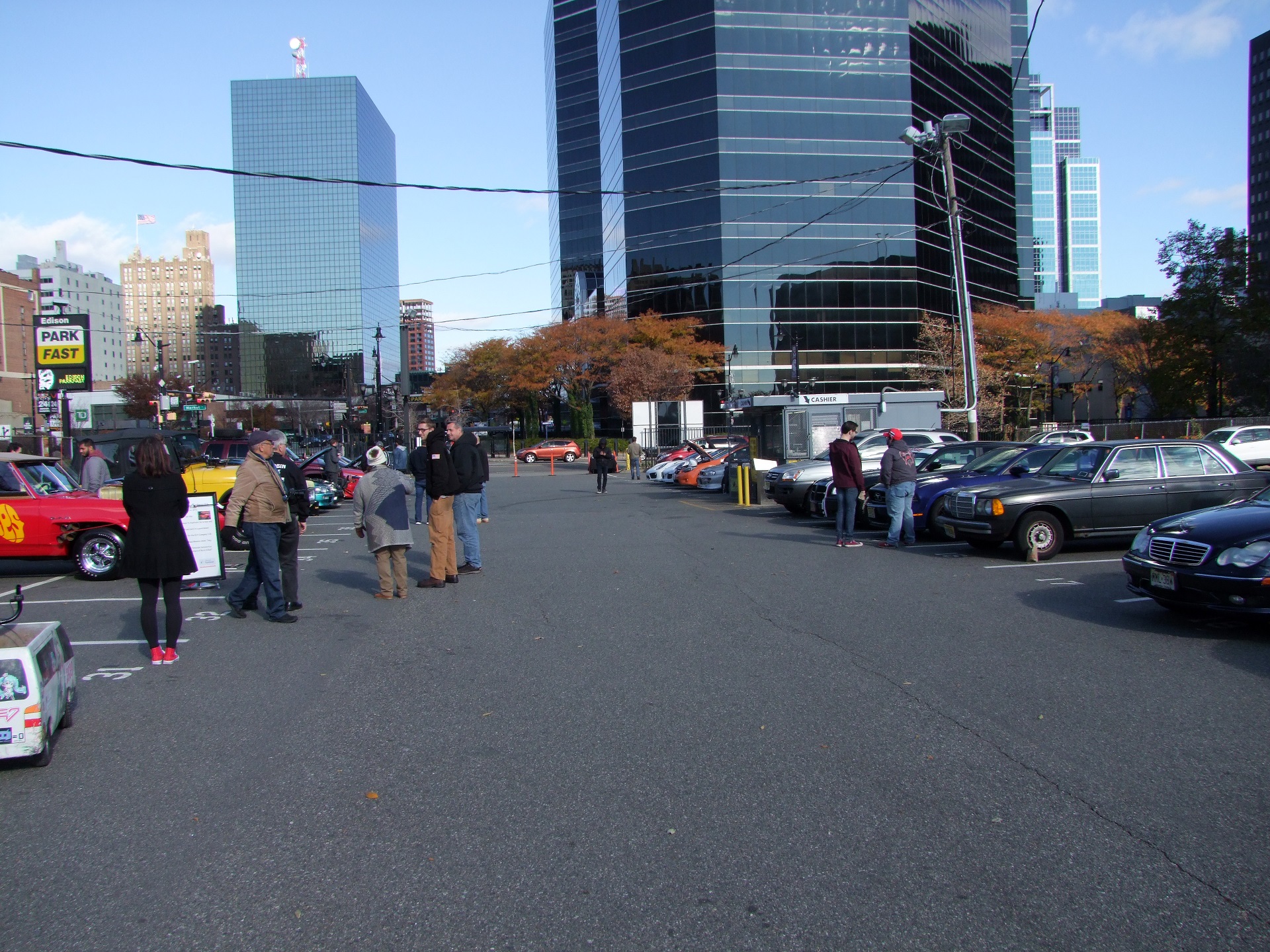
The closer we got to noon, the more interesting things became.
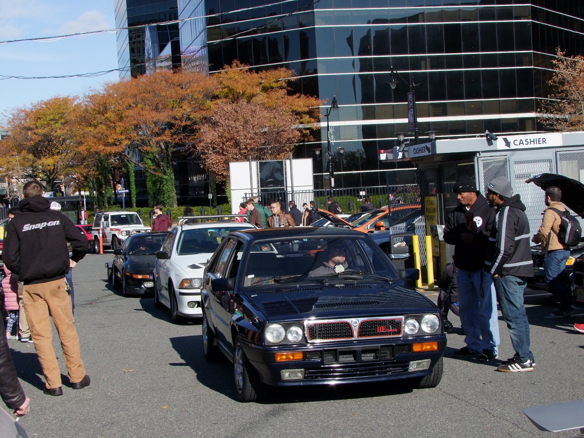
It’s 12:30 now, and we’re starting to have serious traffic problems. Got it – so that’s what “show up early” means!
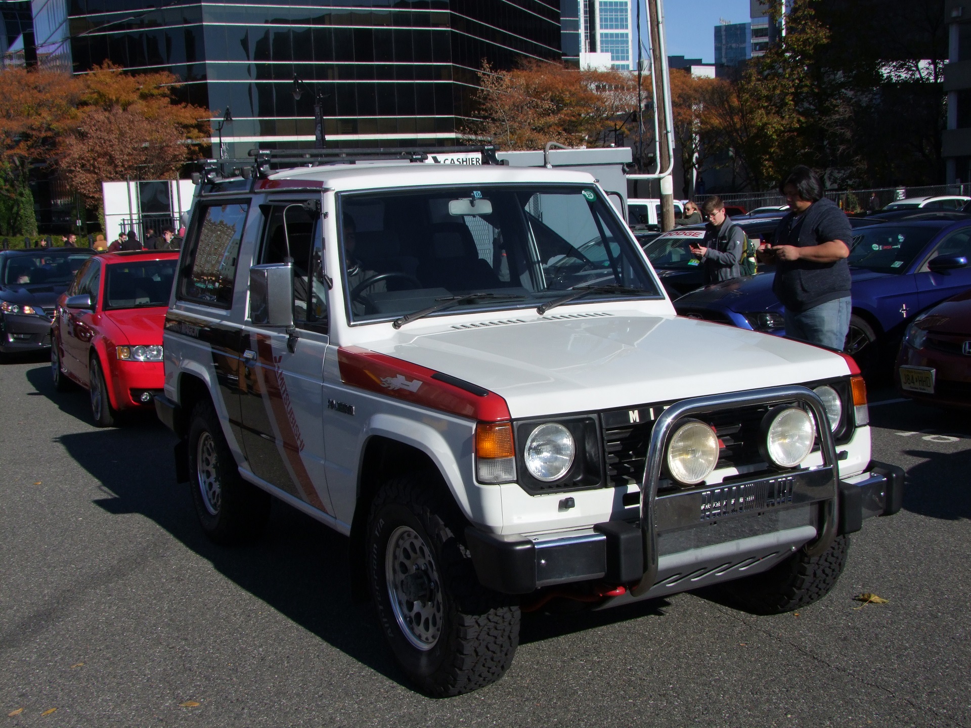
A Mitsubishi Pajero appears! This thing with a Mikuvan bolted to it is the international 4×4 Delica Star Wagon. They share a powertrain and running gear, whereas the 2WD Delicas (Mikuvan included) share more parts with the 2WD pickup truck.
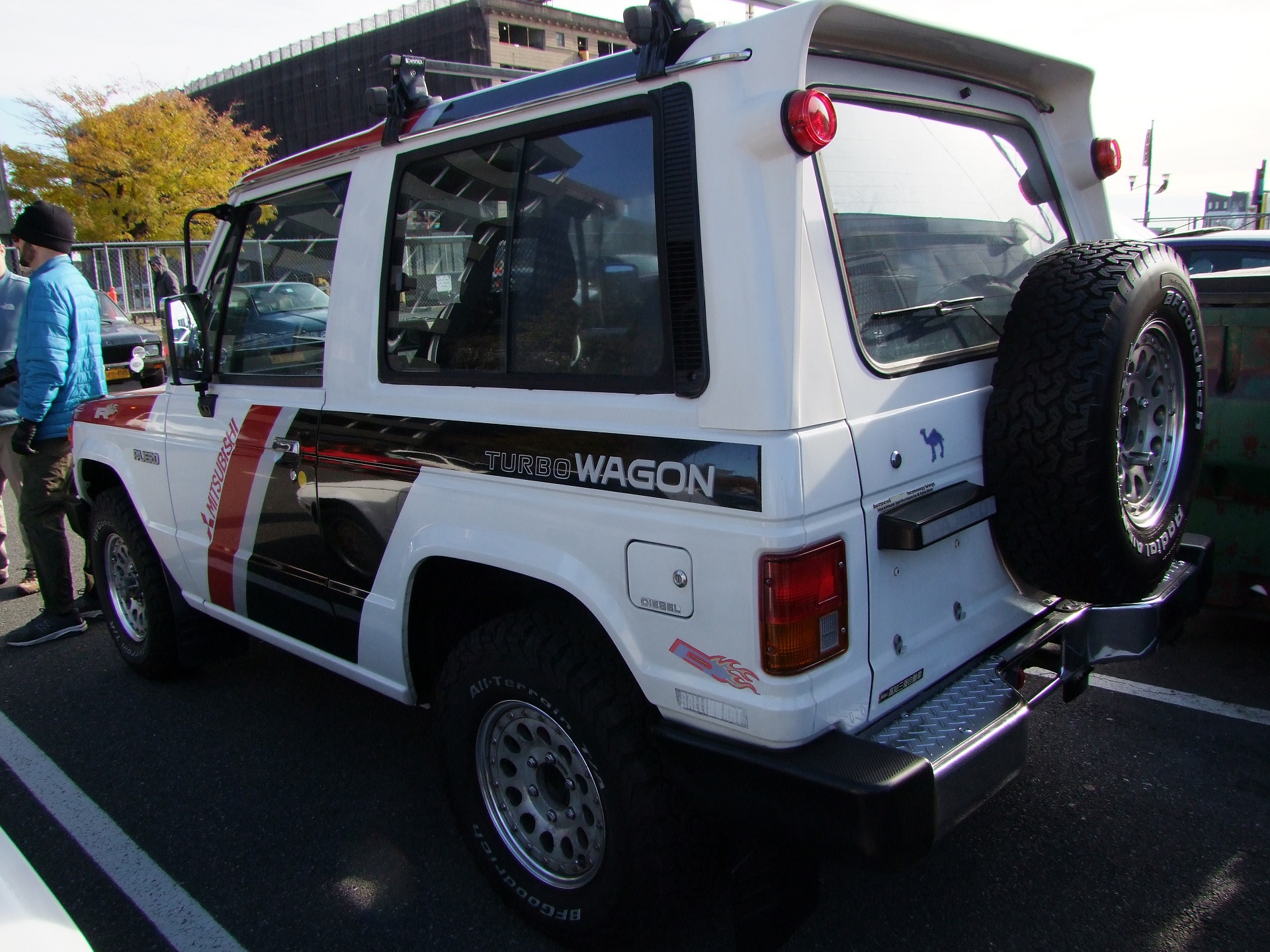
This Pajero was indeed the turbo-diesel version, and a recent Japanese import. jdm
itp: hipsters
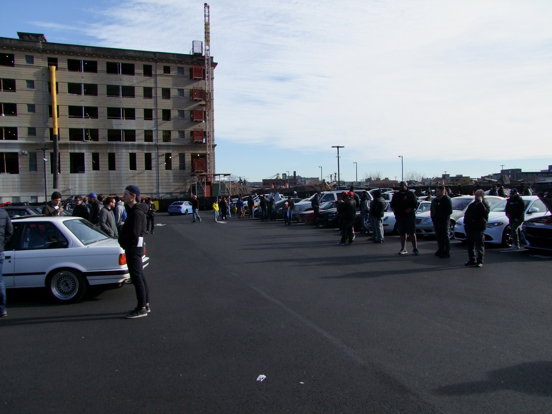
By 1PM, they had to commandeer the neighboring parking lot for all the Chad-come-latelys.

i have money watch me spend it
Okay, okay… that’s harsh. I am sure the owner of this McLaren 720S is a swell fellow. I think what I found endearing about the Jalopnik Car Show overall is that the variety was so not car show, by design.
I’ve been to ones which were Camaro-Mustang-Corvette-Lambo-Stance-Stance-Revolution where every entry was meticulously detailed and shiny and hardly looks like they’re driven. I don’t believe in trailer queens personally – despite keeping my machinery in good running order and generally sound cosmetic shape, they’re not perfect because I use them daily.
In the same vein, I’ll repair and upgrade but never restore Bridgett or Taki-chan, because you create a machine too clean and shiny to be used. Someone else can do that. I don’t want to be hit with regret every time I drop a piece of stock, much like I prefer to be fearless with Mikuvan and occasionally push dumpsters a few feet when the hauling company can’t be buggered to place it back such that it doesn’t block the loading dock.
tl;dr don’t hand me a nice thing
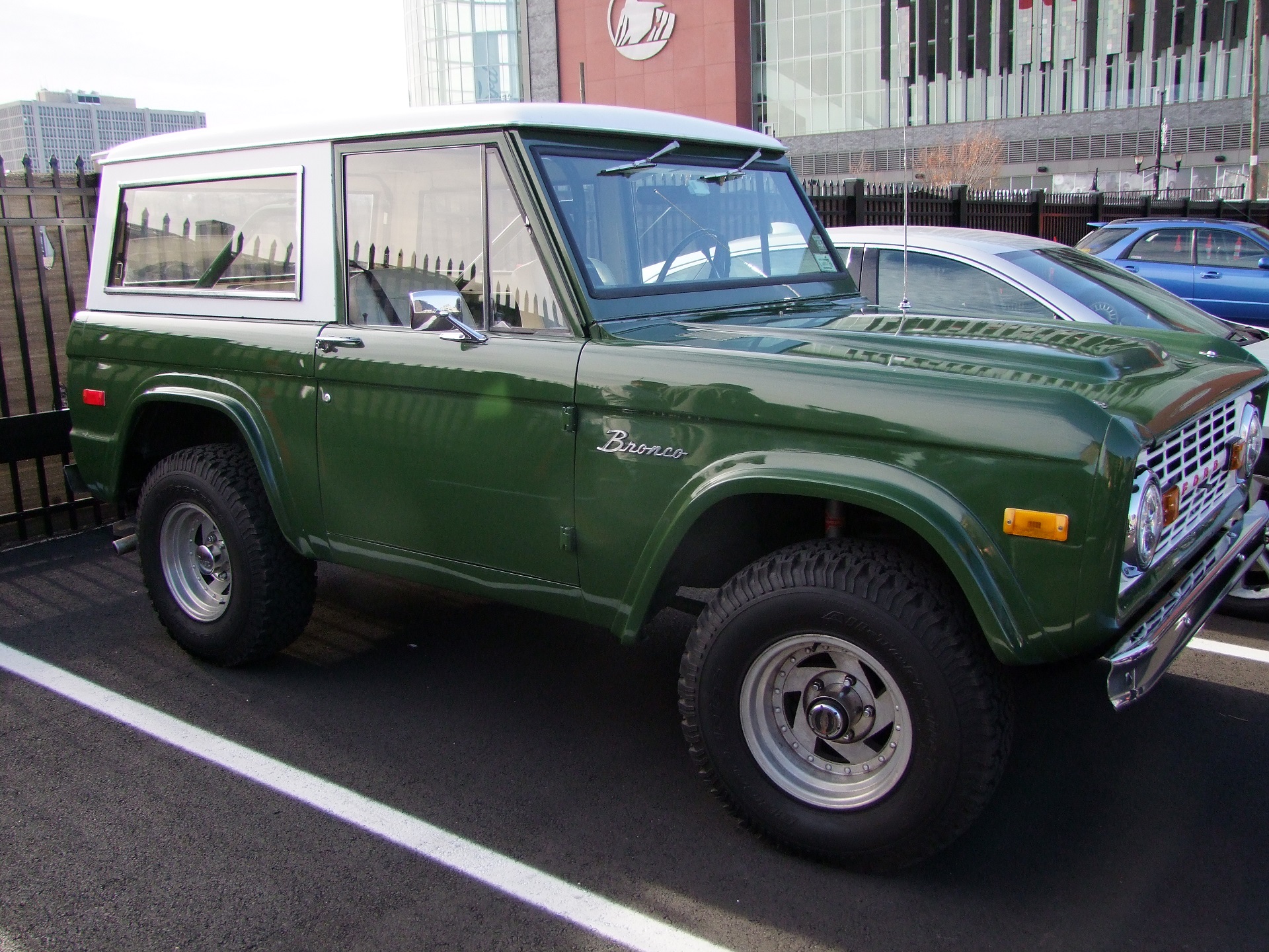
Hey, another truck-like thing! This Ford Bronco is of the first body generation, prior to Vantruck’s year range. It was one out of only 4 or 5 SUVs/jeep-shaped objects, counting the Mitsubishi Pajero.
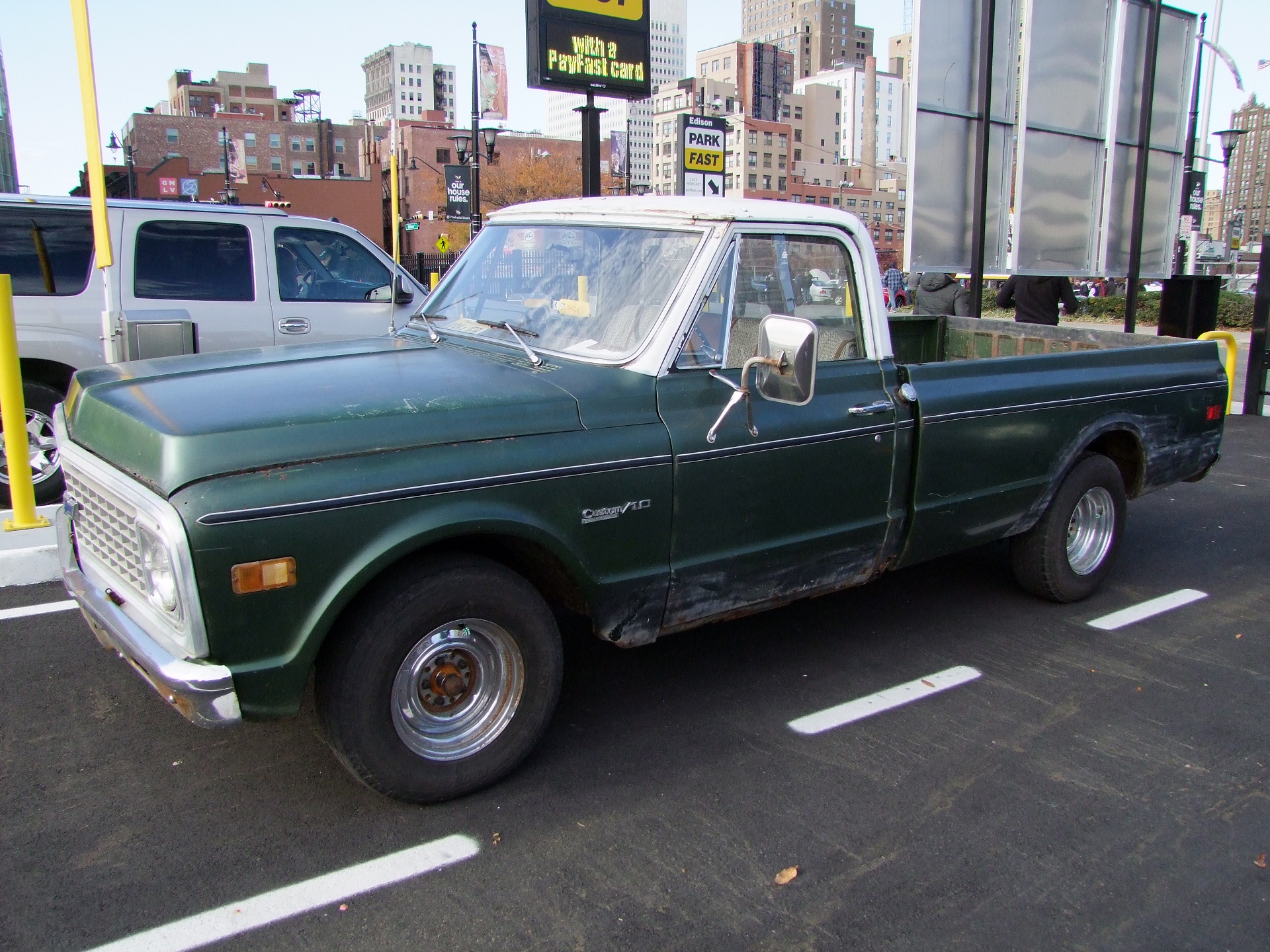
And another pickup truck, what a relief to see.
Overall, Vantruck was the only van/conversion van of any type (not counting CMV, of course) and one of only three trucks present, and literally only van-truck of course. Counting CMV, I also had the only van, only cab-over van, and only electric van.
Hell, it was the ONLY electric ANYTHING. If I had one thing to be disappointed about this show, it was the lack of electricity. Surely someone thought about coming with a Model S or a Chevy Bolt or something? Nope.
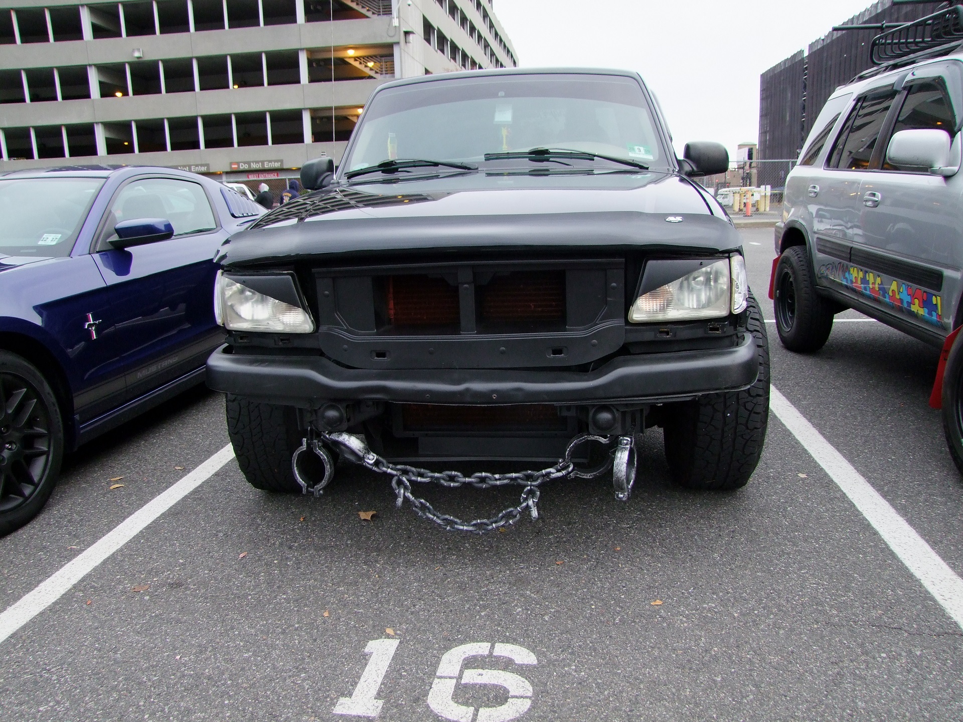
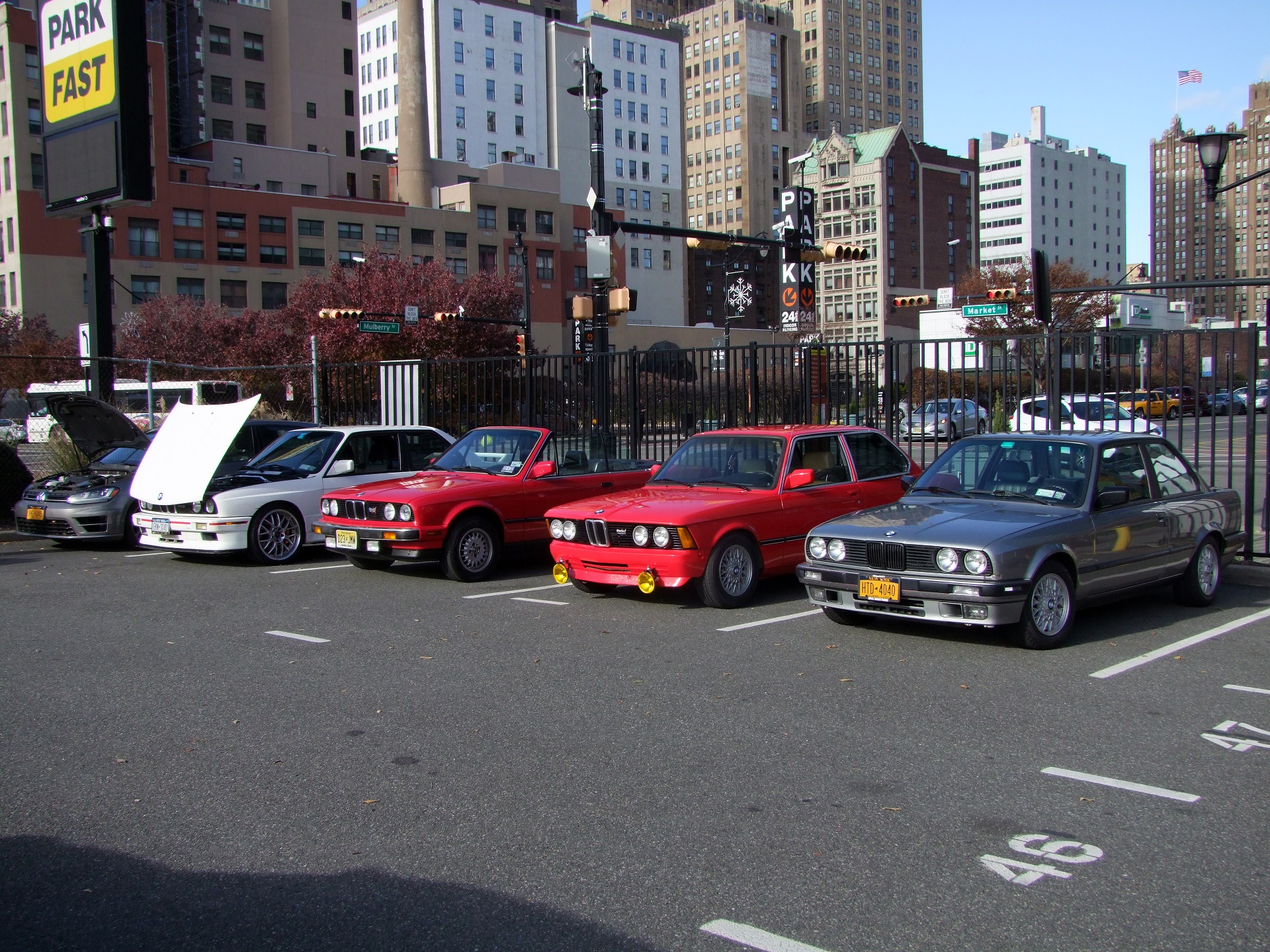
AAAAAANGRY HEADLIGHTS
My other takeaway from this show besides my aforementioned desire to never own a nice thing is that even show cars aren’t all perfect. Again, my only experience with car shows prior to this is ones where everything has an aura of perfection and polishedness along with a nose-in-the-air presentation vibe. So I had a skewed perception of “car people gatherings” as a bunch of perfectionist snobs. I had never wanted to bring Mikuvan to a show since it’s full of my mechanical cockups and bodges.
I think overall going to a show like this was a good confidence booster. Hell, even the Monkees replica car (1st photo, behind Vantruck) had clearly patched and painted over spots where the bodywork had cracked or deteriorated, and a lot of the more nicely finished modified/tuner cars had stuff just hanging off them and random dents and paint chips. However, again, that to me is more honest than a perfect display piece and ‘matching numbers’.
malignant vantruck syndrome
About two weeks ago, I was making my usual patrol rounds using my pre-generated Craigslist searches…

Yes, I have a couple of those in places I often go. Vantrucks show up not that uncommonly – I’d say once or twice a month. But generally they’re either extremely beat up & have sat outside for 20 years, or pretty severely overprived for the condition they are in (e.g. literally over $9000).
This one popped up, though, and it was in a near perfect combo of condition according to the seller whom I talked to on the phone, initial price, and closeness.
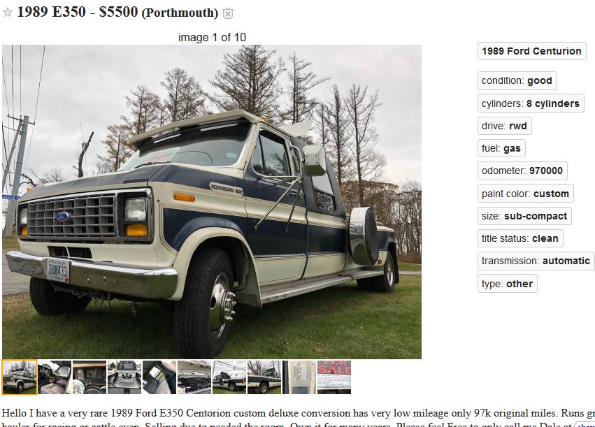
So naturally, I had to go and check it out. Portsmouth is but 50 minutes away, or an hour and 15 minutes in Vantruck speeds.

DOUBLE VANTRUCKS! The cause of global warming is right in front of you, ladies and gentlemen.
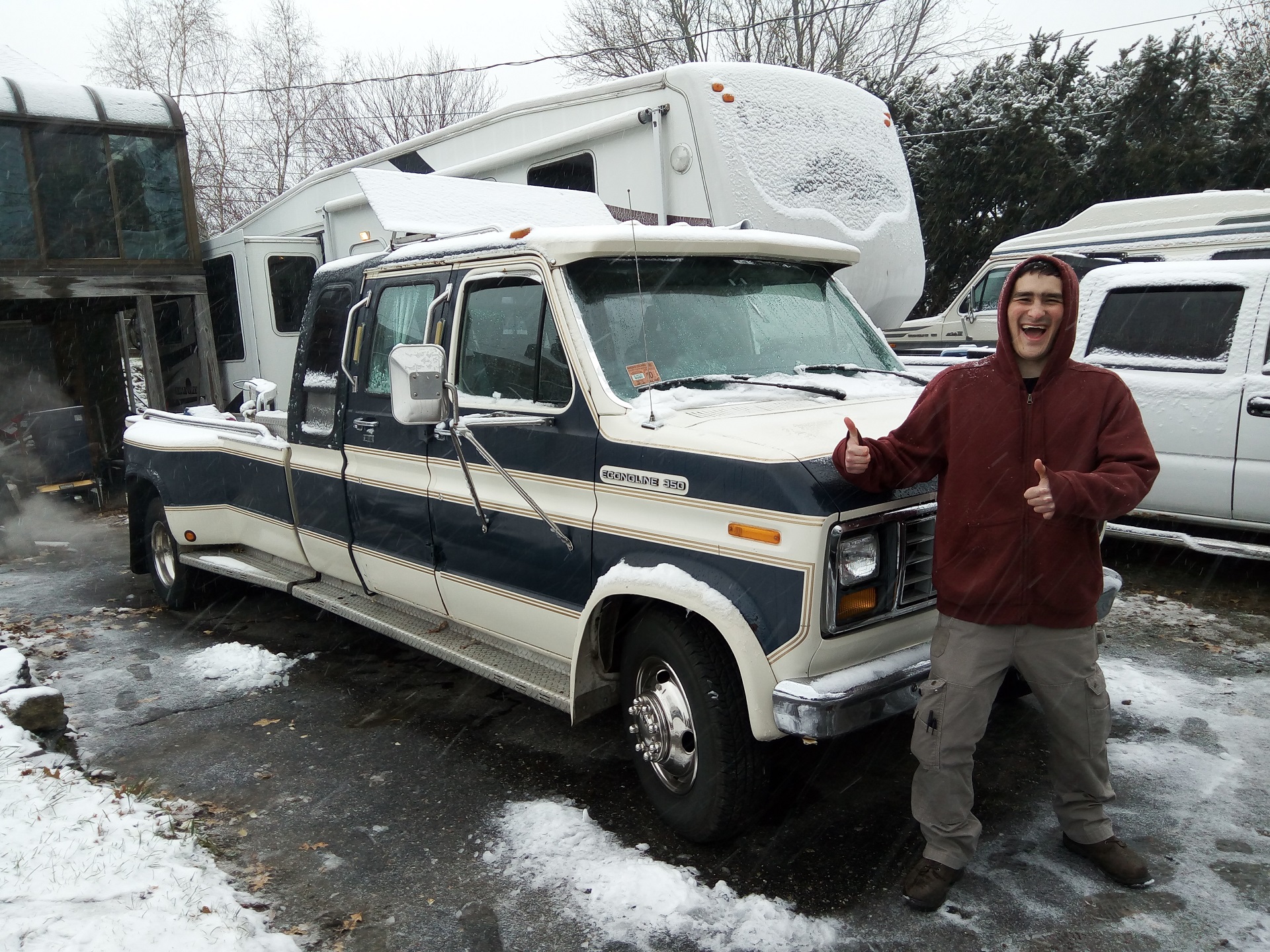
This one is indeed in very respectable condition. The owner is a retired engineer who has had four of these things throughout recent history. How do I know this? He had a dedicated photo album, each photo laminated and in a pocket, of all of the repairs and modifications he’s done to all of them. I want to say “wow, this guy is like me but with real life pictures” but the magnitude of things is so different I can’t begin to use myself as the reference point. It was, though, very inspirational to see how excited he was about all the ones he’s owned and the customization work he’s done.
Anyways, the best crusty old vehicles are usually owned by dedicated retired owners. This one had a slew of mechanical work and replaced components in the past 25,000 miles that I won’t bother listing here. I did some sleuthing underneath to determine the state of the frame and other bodywork. The interior is immaculate and all of the coachwork is original.
So you might think that I went ahead and expanded my aircraft carrier fleet. Well, kind of….
The trip was actually a scouting mission for a robot buddy, Alex of Wedge Industries, a long time northeastern robot competitor. In fact, me versus him was the Franklin Institute finals in the 30lb class. So now this thing is in the robot family… and Motorama 2018 is going to be certified dank.
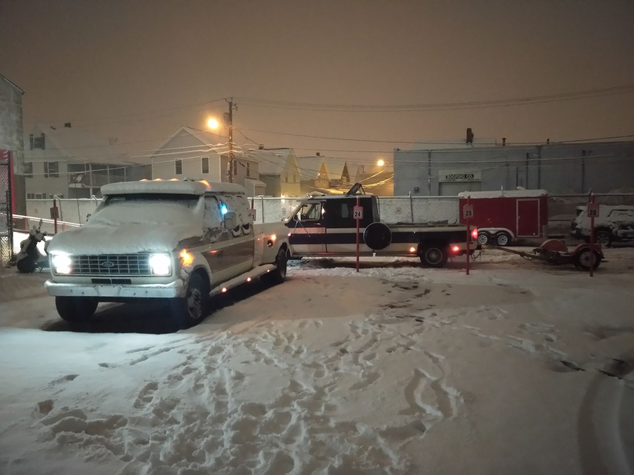
I was going to Double Vantruck to go meet him for pickup, but the heavy snowfall on that day caused me to rethink that plan and I instead headed out with someone else who had 4×4 and a not 70/30 weight distribution. Here, Alex stops over in the shop after getting a trailer to tow his own car back with. Have fun with your 9 miles a gallon all the back to Pennsylvania :p
I now leave you with this.


