Alright! Welcome to another exciting episode of “Wait, when did this become a car blog? I thought it was about brushless motors!” Well, just like how I commit horrible abominations to the industry of mechanical engineering daily, here is an abomination for gearheads: If you ever wanted to mate a truck bed to a van frame, this is your moment. Because I’m about to do just that, and put it on record.
As soon as I got VANTRUCK running (even if a little off-tune), I called a convention of my somewhat automotive-minded friends. We’re like the Justice Friends of working on silly vans. Together, we will take on the challenges of…

Oh boy. This mess needs to be unstacked first, then we deal with everything else. This assemblage was referred to as “bunk beds”, lending the name to this glorious undertaking. In one work afternoon we planned to remove the old bed and at least inspect/plan for new bed install. It was known to not be a drop-on installation, at least not with our knowledge of the light truck universe. That is, someone who has worked with Ford products for years could probably have identified a shortcut or workaround by reading on… well too late, we already did it the stupidest possible way! Actual installation was to be another day, with a week in between (where people had real jobs to attend to) where I would pregame making the needed brackets and assembling hoisting tools.
Removing the F350 bed from the stack was a 4-person job that involved sliding it backwards off the old bed and standing it upright on a large sheet of cardboard. It was then slid out of the way on the cardboard. I’d estimate it weight around 300-350 pounds – we could all handle it, but not with much finesse and certainly not for long.

So here we go! The first task in removal was identifying and removing all of the bolts holding the old bed on. The rusted-in-place carriage bolts with nuts underneath hidden by fuel tanks, crossmembers, and suspension components.
Half of the 12 carriage bolts were simply cut off at the heads because well, am I gonna reuse this? No. and the other half came off with differing amounts of effort.
This adventure took up a full half of the afternoon alone, and made me swear off the use of any independent nuts in the new mounting scheme. I’d much rather tighten bolts into threads that are machined into or welded onto (via weld nuts or tapped spacers/plates) the new bed mounting cross-members, than ever deal with a rusty Ny-lock nut again.

Lacking any sort of crane or hoist, we improvised with shoulder-slung steel tubes. This worked okay and clearly let all of us see who was the manliest man to ever man. Hint: wasn’t me.
This custom bed probably weighs north of 400 pounds (and is enormous) and while we were able to remove it, it was not with any precision. We basically dragged it off over the wheels.
This cannot be the case for the new bed, because it would mean a lot of damage to the underside. It’s built with more heavy steel than the F350 bed; we all thought it would weigh less, but in my opinion it was actually substantially more. Probably because it was designed from the start as a 5th-wheel mounting point.

And here it is, I now have a Vant. We just removed the -ruck part. There’s a lot of interesting and absolutely terrific things going on under that bed. First thing to note is it’s all mounted to 10 rubber body-mount bushings, not directly attached to the frame in any way. I don’t know if that’s normal for truck beds in general.

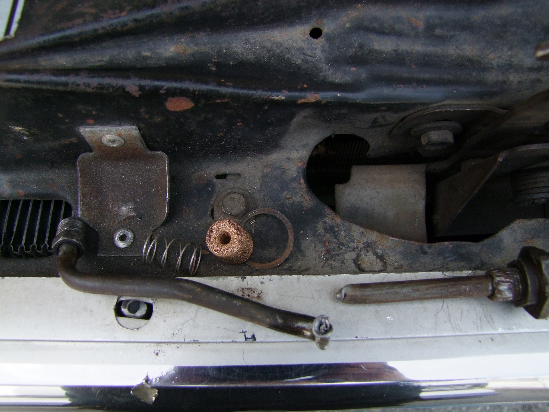
These are what I call “Precision Van Spacers”. They were under every crossmember, in varying amounts. I don’t know if these were “factory” or if someone installed them “aftermarket”. A good laugh was had by all.

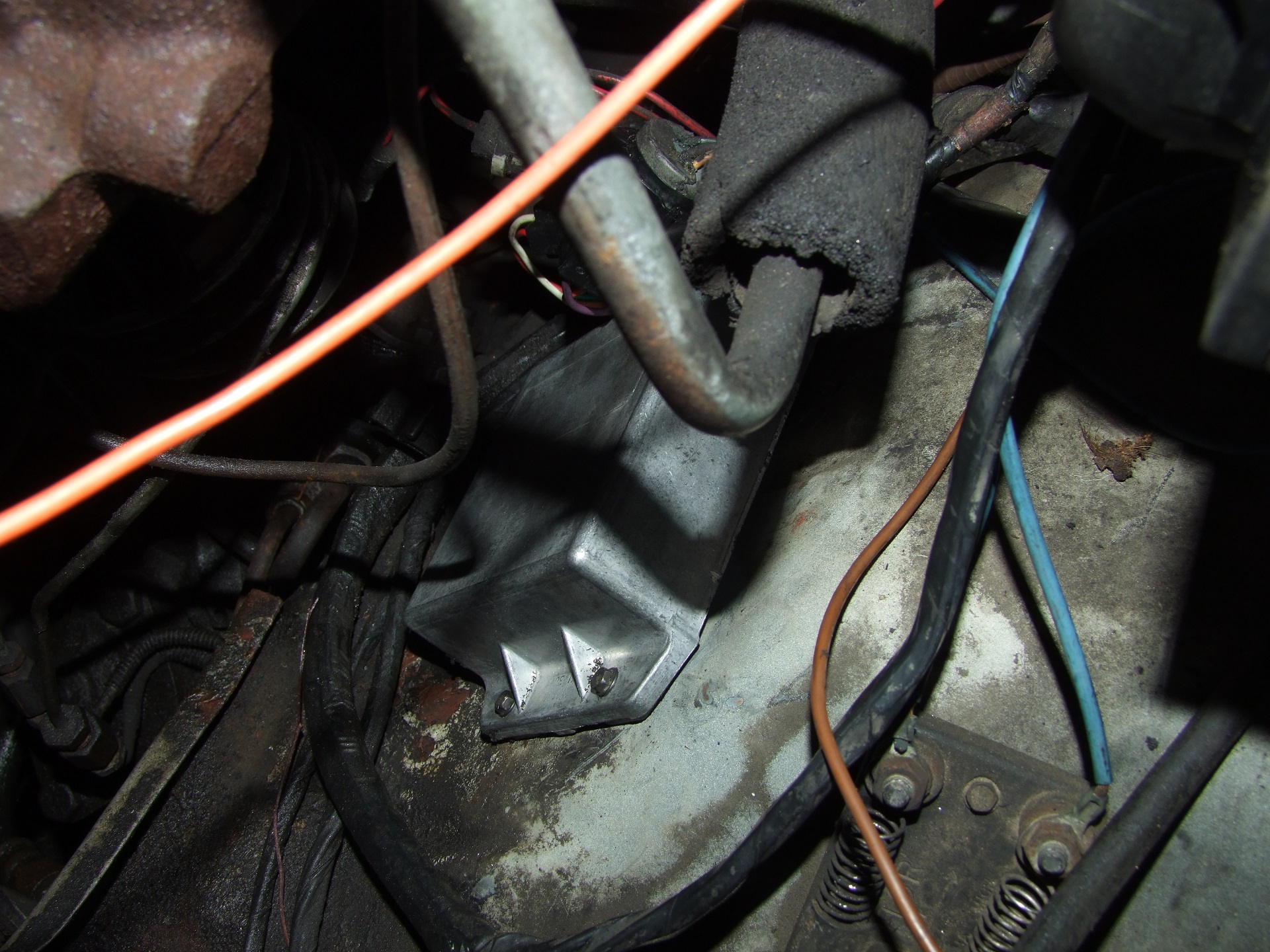
What made me wonder even more was this large 5th-wheel hitch mounting plate. While it had Precision Van Spacer mounts in the end crossmembers, it was also welded to the frame through the angle brackets, here seen cut through with a grinder. So was the bed floating or not!? Anyways, this contraption had to be totally removed. It looks like it was supposed to be bolted through drilled frame holes, but someone made some interesting van decisions. I’l likely grind the remaining tabs more flush later.

I took the bushings off and….. I should not have taken the bushings off.
I didn’t need to see this. 1980s mulleted chain-smoker Charles would not have bought one of these now that he has had a good look at the build quality and, umm, craftsmanship.

So that’s the conclusion to Day 1 / Week 1. I now had to measure out and plot how to make new crossmembers to take advantage of the existing ragged Glory Holes torch-cut into the frame. <:(
I knew what I wanted was all topside service (no one guy above the bed, another underside, with some combo of breaker bars and push-me-pull-you dances) and no nuts. The new crossmembers would be fewer in number, as the F350 bed only has 3 rows of mounting holes, and likely just a flat slab of thick steel so I can thread into it directly.

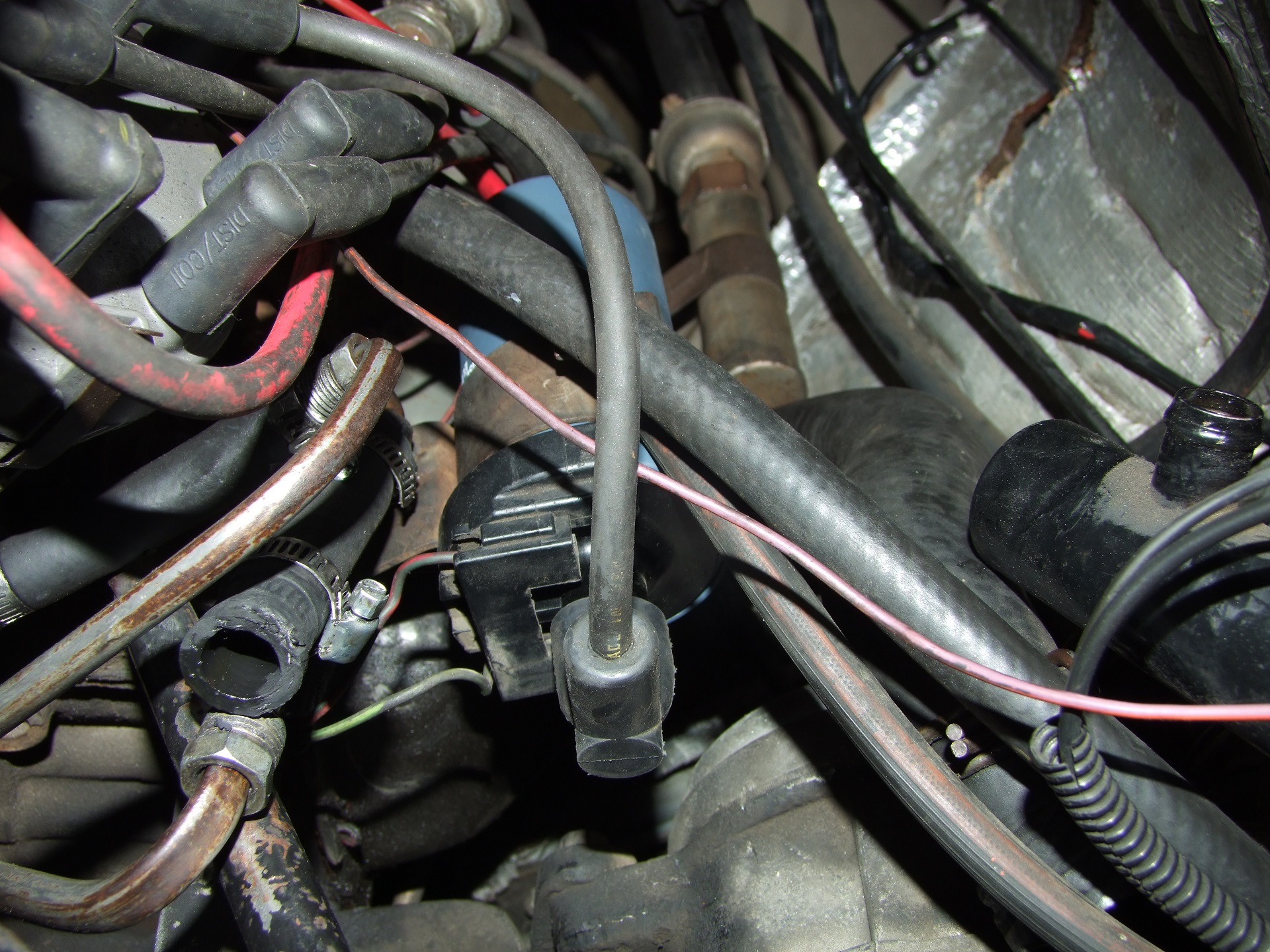
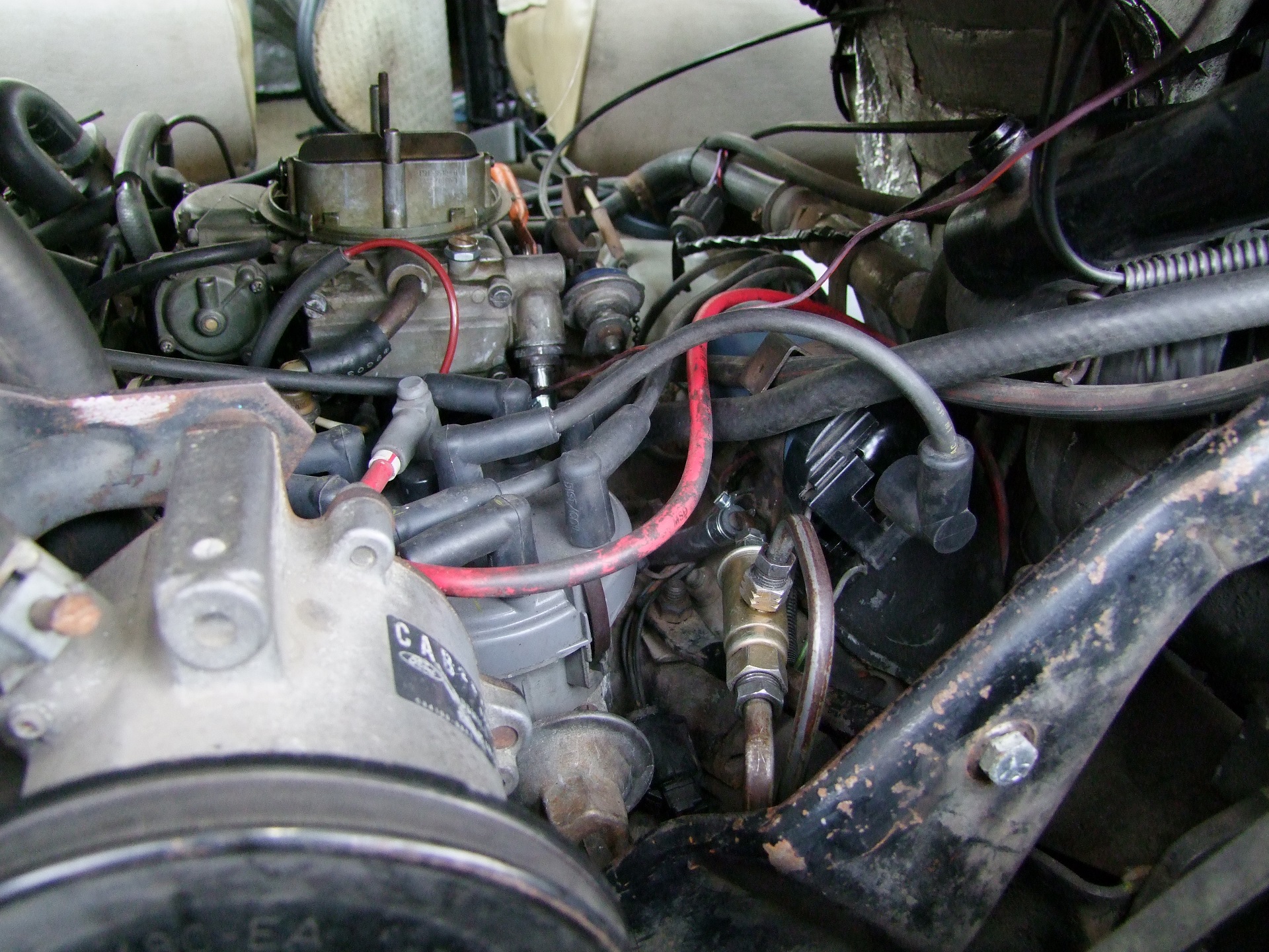
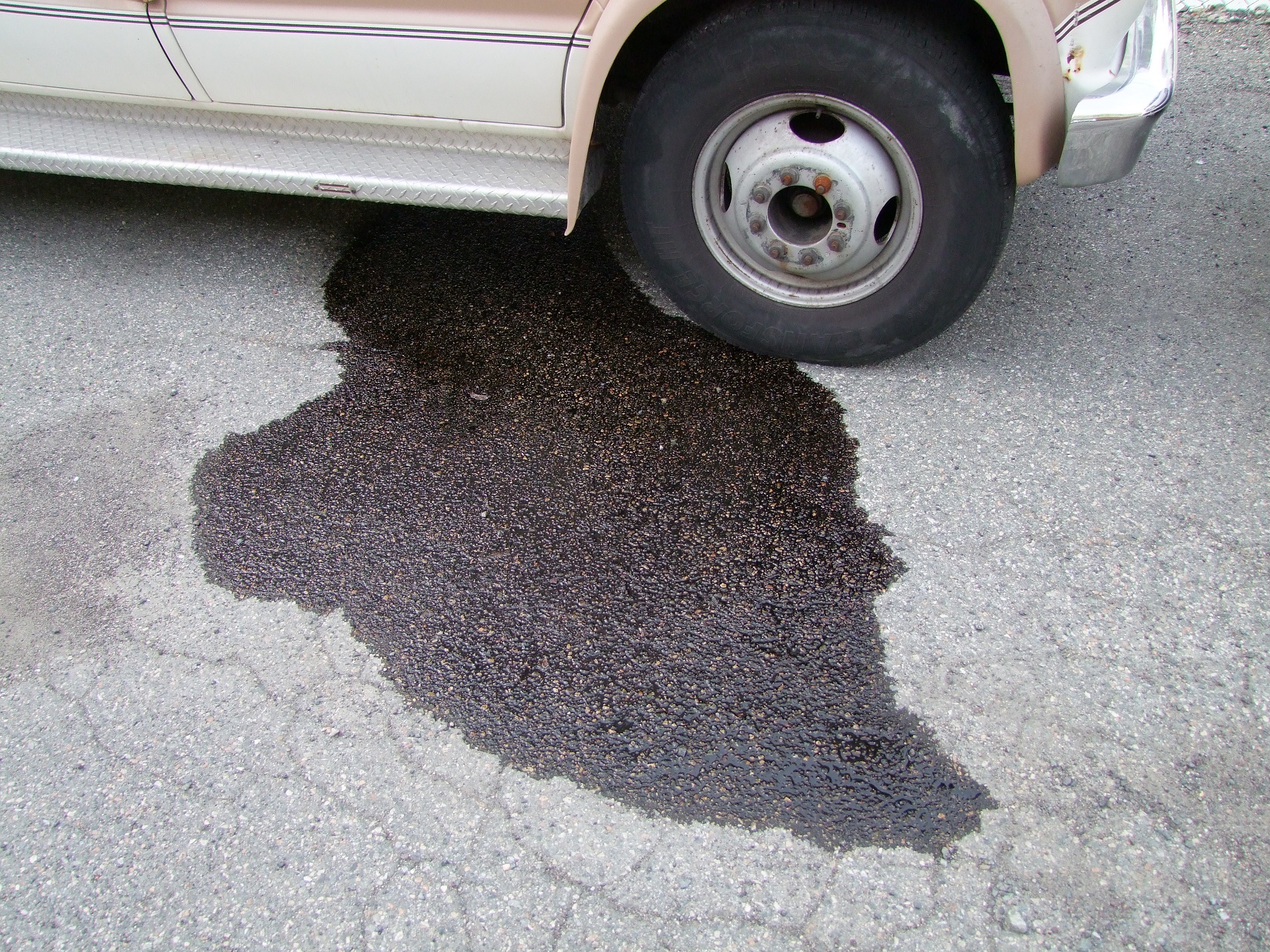
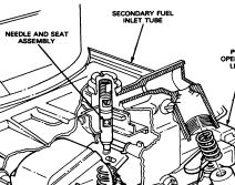
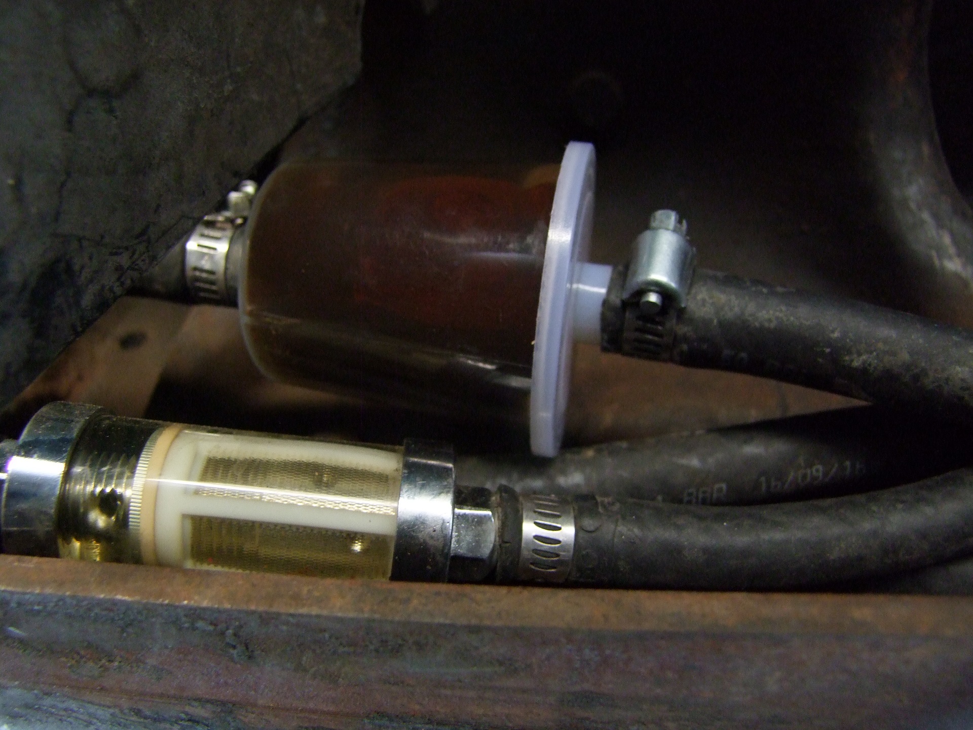
Hey, look what’s easy to reach now! I replaced the rear fuel pump assembly and gauged the condition of the tank. Verdict? The rear tank is in much better shape than the front. This means the front tank had been out of service potentially for a year or two, if not more, gauging from its interior condition and the state of the remnant gasoline I pulled out. The rear would have been in use and cycling fuel through, preventing a lot of corrosion. The rear fuel pump wasn’t bad either, but the fuel gauge resistor strip had worn through (that’s why it didn’t read properly).
In the intervening week, I decided to just buy a Harbor Freight engine crane. I’ve had reasons to want one before, but never pressing ones such as “The landlords are asking why I have truck parts strewn about all over the parking lot”. As I mentioned above, we were not going to be able to wrestle the new bed on with any degree of precision, at least not with the GAINZ we’d be able to pick up in only a week, so a hoisting device was needed to take the weight while we did maneuvering only.
I also researched how people manipulate truck beds. This video (mute the soundtrack -_- ) ended up being my example, since he used the Harbor Freight engine crane. I’ve also seen two-crane dances and gantry cranes; while I would love to have a portable gantry crane, it’s basically a rigging job to buy one on its own and I decided it was beyond scope for the time being.
There was only one problem. The 2-ton Harbor Freight crane wouldn’t have reached far enough into the bed to balance it, since the truck in that video has a short bed (6 foot) and I have a long bed (8 foot). We thought about a few ways to counterbalance it, but ultimately I decided on doing it My Way.
This is #OSHAcrane:

Look away, Harbor Freight lawyers.
That’s an extra-long piece of 2″ square, 1/4″-wall steel tubing I drilled and machined to accept the same mounting hardware in order to make an extended reach crane boom. Not shown is a steel biscuit that fits under it to take up the height difference between the outer tube and new boom. Otherwise it would have tilted down significantly and stressed the outer tube a lot more.
In terms of dimensions, the Harbor Freight crane is made with metric (C H I NA ) steel tube as far as I can tell. The inner adjustable boom measured 2 3/8″, or right around 60mm. I couldn’t get 2.25″ tube locally in time, so opted for thick-wall 2″ tube. If I wanted to make this again more correctly (…) I’d try to order metric steel tube online.

#OSHAcrane has about 18″ more reach than the stock crane. Shown under it is the two steel slats I’ll be making the new crossmembers from! They’re 8″ wide, 42″ long, and 1/2″ thick.
They are not light. But neither is VANTRUCK an aircraft or drone* and it really does need more weight over the rear axle anyhow.
*yet.

I arrived upon this dimension of steel plate by measuring and laying out the known mounting dimensions of the van frame and truck bed. I then picked two sets of body bushings which were the closest, and basically wrapped a rectangle around them.
The rear set of bushings would need to be moved up a few inches to accommodate, but I found that 8″ wide steel bar was sufficient. Otherwise, if I chose to not move the rear set, I’d need a 12″ wide slab.

Good thing I just got a milling machine running, huh? Bridget proved to be indespensible. I’d hate to have done this with a drill press, also inb4 get a plasma cutter. how about no

This is a finished replacement crossmember. The big hole is 3/4″ to clear a 1/2″ bolt with Van Precision – these get installed and tightened into the body bushings first. Then the bed is dropped on top and bolted from the top into the 1/2″-13 threaded holes.

Here they are installed! I had to machine out a portion of the forward crossmember to fit over the fuel pump.

Now it’s Saturday again, and we are once again gathered to shift heavy steel things a few inches at a time until Charles is satisfied. The rigging begins in the same fashion that the Ford Lightning bed removal video showed, using 4 ratchet straps, one to each corner of the bed. You can see that #OSHAcrane reaches exactly to the middle of the bed as designed!
” DESIGNED “. I make myself sound so serious.

This worked extremely well. The bed was raised just enough to move around…

…and up and over it goes! Flawless. We did exactly what we set out to do – provide guidance force only, and hold hoses and wires out of the way.

A snag – the shock absorber towers in the rear line up with one of the stock F350 bed crossmembers exactly. Well give me a carbon fiber enema…… why don’t I just mount the bed to those?
A half-hour of awkward step-drilling was needed to buy it some clearance. I drilled a sufficiently large hole such that the shock studs fall into them on each side.

Next snag! Ford, you assholes.
The rear set of mounting holes? 34″ apart, not 35″. It was high enough up that I had a hard time getting a good visual alignment of the tape measure, and ended up making Certain Assumptions that “oh maybe they did a logical thing and made them the same so it’s easy”
Back to the mill I go….

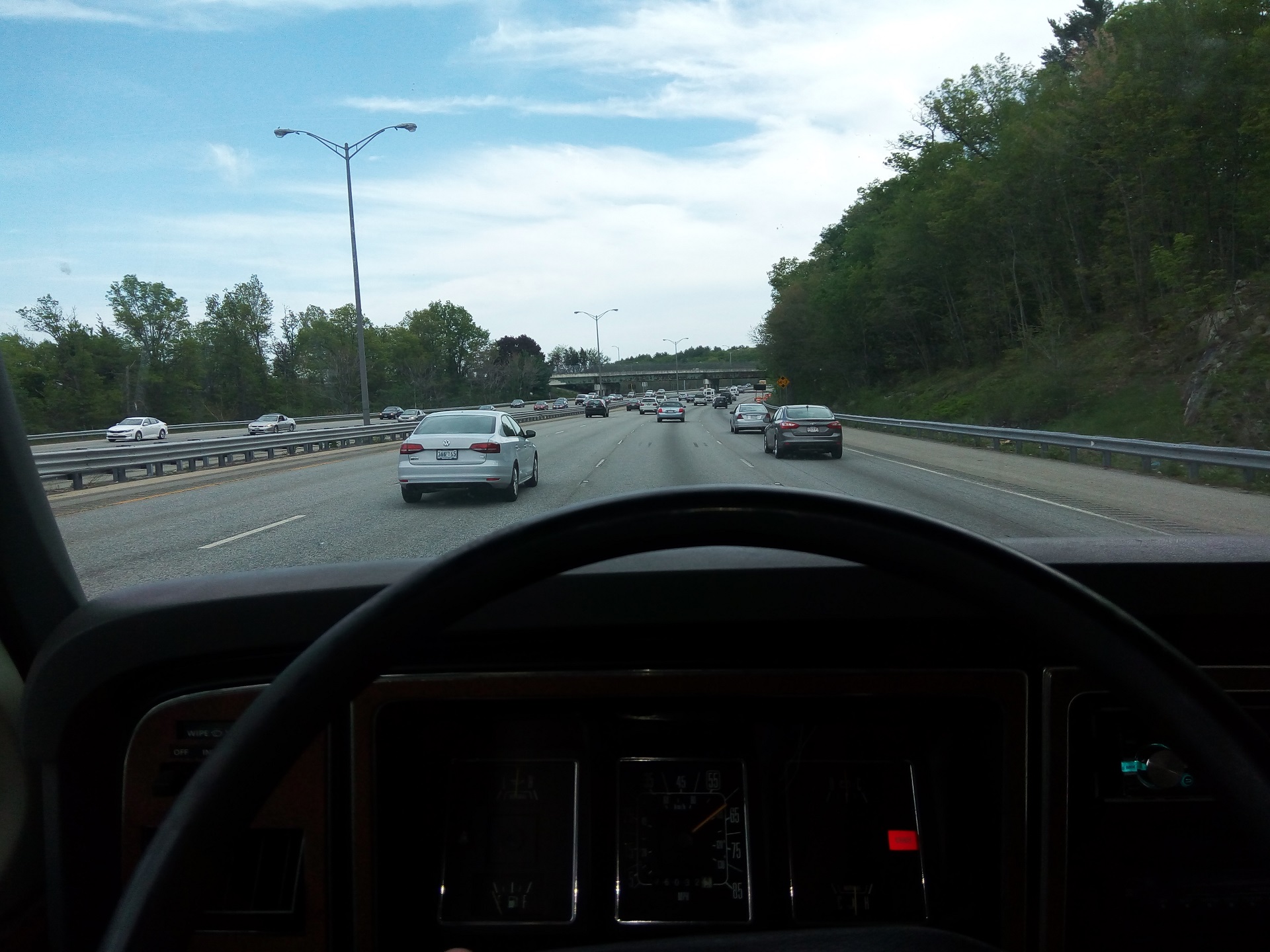
After that fight was settled, the bolts were tightened down, and IT’S DONE! HOLY CRAP IT’S IN ONE PIECE AND IT RUNS AGAIN!

Here it is from the side. And you know what? i hate it.
Okay, not really, but now I am really thinking about a revision.
As we were drilling the two new holes for the rear crossmember, the thought suddenly occured to me that…. you know what, what if I just drilled new holes where they’re supposed to be, aligned with the truck bed crossmembers, so I didn’t have to use such wide steel slats? I didn’t know how hard it would be to drill new holes (surprise: truck frames aren’t made of AR500 or anything, a step drill works too) so opted for the safe and quick solution of wrapping a rectangle around it. I was out to quickly get it back in one piece to not piss off the neighbors, over anything else, optimal solution be damned.
Second of all, I didn’t have a good way of determining the alignment vertically – the van frame curves up and down and was hard for me to get a datum off, especially in a beat up and unlevel parking lot. So this first pass at mounting it let me see what needs to move where.
I’d like the front edge of the bed to come upwards about 1″, and the whole thing should move forward about 1/2″ to close the epic cab-to-bed gap. I designed in the gap as a safety measure – would rather have too far than interfering – and now I’ve had a chance to see how it actually goes together, I can move them inwards for a more factory look…. not that the body lines meet or anything.
So there will be a Second Battle of Bunk Bed Hill. Especially that I know it’s super easy to lift the bed off with #OSHAcrane! I wouldn’t even need to lift everything, just one side at a time. I’m plotting the new crossmembers as 1.5″ x 3″ or 4″, 0.188 wall rectangular tube, and the new rear as 1/2″ thick x 3″ or 4″ wide steel strip. The tube would have machined 1/2″-13 coupling nuts welded through it to act as a tube boss (so the bolt isn’t just pulling on one wall of the tube) and the rear strip would be similar in construction to the current one.
With a significant source of stress lifted (heh) off my life by #OSHAcrane, I could now sleep easier and start picking at some of the smaller tasks. For instance, hooking up the new bed’s taillights. This first required some van spaghetti untangling:

Here’s all the factory, aftermarket, and after-aftermarket wiring extracted from the old bed. The F350 bed has all the lights terminating in a single connector, which is nice.

What’s not nice is not being about to find or source the matching connector. So I decided to improv and pulled out a 7-pin military surplus Amphenol connector from MITERS. Now I have even more America on this thing! Military-grade hardware!

Decoding the Ford connector was easy with a multimeter (and battery + suicide cable to see the lights turn on and off). All it then took was cutting off all of the van spaghetti and reaching back into the frame to grab the OEM wire harness and pulling it out. Here’s the terminated non-spaghetti lighting harness mated to the new bed.
The little green wire is a detail for later. That is supposed to be connected to the brake pedal switch directly, apparently so it can power a CHMSL. Vantruck does not have one, and I currently have no plans to install one (though if it will help keep texting idiots off my new bed…..) so I wrapped up this pin in the bundle for now.

All of the extraneous spaghetti removed, along with what sockets and bulbs I could salvage.

Something something about being lit, fam (shoot. me. now.)
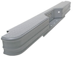
The last major mechanical task is mounting the new step bumper, which has to be mounted on a long extension bracket to clear the bed. The Ford E-series step bumpers I bought do not have a cutout on the corners to fit around the bed like the F-series bumpers do, so I have to mount well behind the bed. I’m talking like a 8″+ extension bracket. This will be performed after I make adjustments to the bed position.
I will probably take a short break from Vantruck work, since it fundamentally is back in one piece, runs well, and is street legal lighting and fenders-wise. At the least it can get out of its own way. Look for more work on Brushless Rage coming soon, because I want to push that damn thing to beta and to release this summer.

