A Mikuvan Subproject: Operation DERPDrive

I’m going to take a quick break from being too sissy to start on rust repair work to begin a thread for something which has been planned since the beginning when I got the damn thing. As I keep telling myself (I swear this is still true), the end goal of this project is to fully electrify Mikuvan with a Siemens 1PV5135 motor, Azure Dynamics DMOC645 inverter, and a stack o’ batteries from everyone’s favorite undead alphanumeric battery company. When I bought the van in non-running condition, this seemed like an immediate possibility; at the time, neither I nor anyone on the trip were auto mechanics, just your average Battlebots-buildin’, scooter-ridin’ hoodrats.

Well, now that it’s running just fine for some reason, that enthusiasm has been admittedly damped a bit. Taking it out of commission now to drop the engine and transmission out would mean potentially months of MITERS no longer being able to haul hundreds of pounds of shelving and materials on a whim:

We can’t have that, now, can we. But I’m a little too heavily invested parts-wise in this project to never let it see the light of day.

Here’s the trouble: There is a gap of about 1 mile between the shop with a 2-post lift and my actual, legitimate parking spot for this thing, with a rather steep garage entrance ramp in between. I can’t hog the lift or the patch of space underneath it for months on end while working it, and I would hate to ask for a tow or push from someone else every time it needs to move. If electrification started in earnest, there will definitely be a period of time when the vehicle will have absolutely no remote possibility of moving under its own power.

From the start, I pondered ways to real quick rig up a temporary electric drivetrain that could exist wholly independently of the vehicle and basically jam itself under it to move it gingerly around. Ideas were thrown around ranging from what basically amounted to a two-man push-assist made with welding wheelchair motors onto a stick, to hijacking the rear driveshaft directly and basically going parallel-hybrid. At times, the thought of seriously manufacturing a “car tractor”, like a smaller aircraft tug, marketed towards shops and yards was considered.

What I didn’t want it to become was a science project of its own. It had to be quick and dirty, existing just to scoot Mikuvan in the dark of night between shop and spot. It could move at 5mph for all I care – it had to go all of 1 mile, but it had to have enough torque to shove the whole thing up a roughly 20 degree slope.

parts

I consulted the low-orbiting cruft cloud that is the N5x complex and came up with a few candidates for this job.

  • Basically gluing a power wheelchair to it. 10″ wheels, 24v motors upped to 36 volts, and basically 5 miles per hour it was. I had my doubts that the motors would even have enough thermal load capacity to make it that mile. It would definitely be easy. The downside? Not even theoretically enough torque to push the thing up the entrance ramp to my parking garage, and I won’t be able to get enough speed out of them to take a run at it either.
  • Eteks everywhere. Between all the electric vehicle shenanigan hotspots, there must be like five brushless Eteks (now known as Motenergy ME0907s). One would have been more than enough power, but it would require external gearing (slash chain drive). I also don’t have a brushless controller big enough to make this worthwhile.
  • Cap Kart-Van hybrid. The giant D&D sepex motor (Hey guys, how fucking hard is it to give me one damned web catalog with all your motors on it? What is this, 1993?) of the legendary Cap Kart was dismounted a while ago to be used as a dynamometer load by someone that said something about solar cars. Like the fate of many projects at MIT, it never got remounted, and has been sitting on a bench since. This thing, a D&D ES-101A-33 type, is pretty much capable of moving a Geo Metro or something independently, with a peak power capability probably north of 20kW.

Controllerwise, I mined up a working Alltrax DCX500 from the defunct Vehicle Design Summit group, whose materials have been slowly diffusing back into the building’s various tenants. Running at 48v and up to 500 amps and paired with the D&D motor would make a respectable power system on its own – and certainly one hell of an pushing attachment. Parallel hybrid is looking reeeeeal good right now. Needless to say, this combination, with its appeal to my sense of unnecessary overkill and having just the right amount of potential disaster, won the appraisal round handily. The power source would be taken care of by one of the prospective alphanumeric battery modules – we’re not talking Model S class driving range here.

I also scavenged back from MITERS one of my old 11″ (real) go-kart wheels which was going to make it onto the never-built Super LOLrioKart back in the day. At this rate, I might as well just hang Cap Kart, whose carcass is hiding in a corner, off the tailgate and be done with it.

I ran some quick numbers and found that the D&D motor would only have needed around 4:1 of gearing to shove Mikuvan straight out of the garage while pulling 500 amps. Unfortunately this would have also resulted in a go-kart-like speed of about 45mph once I was done with exiting. Appealing, but I would also like to avoid piloting something without power steering or braking at those speeds. An 8:1 reduction would cut the speed to around 25mph with the ability, given enough traction, of shoving Mikuvan straight up a wall. Now, 25mph is plenty to keep up with traffic and have nobody notice that something might be a tad off.

placement

The next question was where to put this complication. For that, I turned to the underside where my spare tire was hiding:

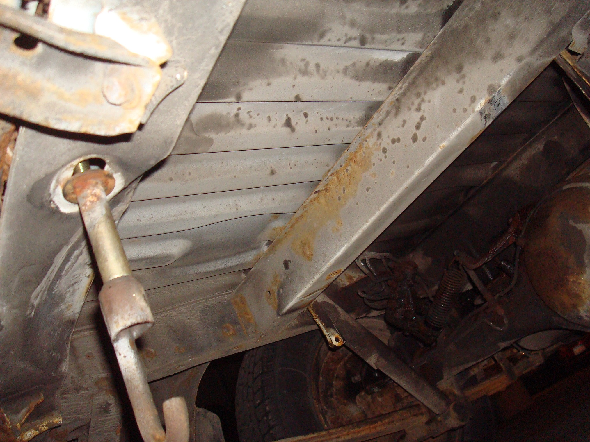
Emphasis on was – the spare tire was basically the first thing I removed and disposed of since the rim was almost completely rusted out. Dismounting the tire and hanger uncovered this pristine area between two parallel frame rails in the back – the “#6 Cross member” and “Rear End Cross Member” according to the manual. These things are (as it turns out) monocoque construction but with a discrete frame structure, so it’s not totally unibody like modern minivans tend to be.

Here’s a better look from under the lift:

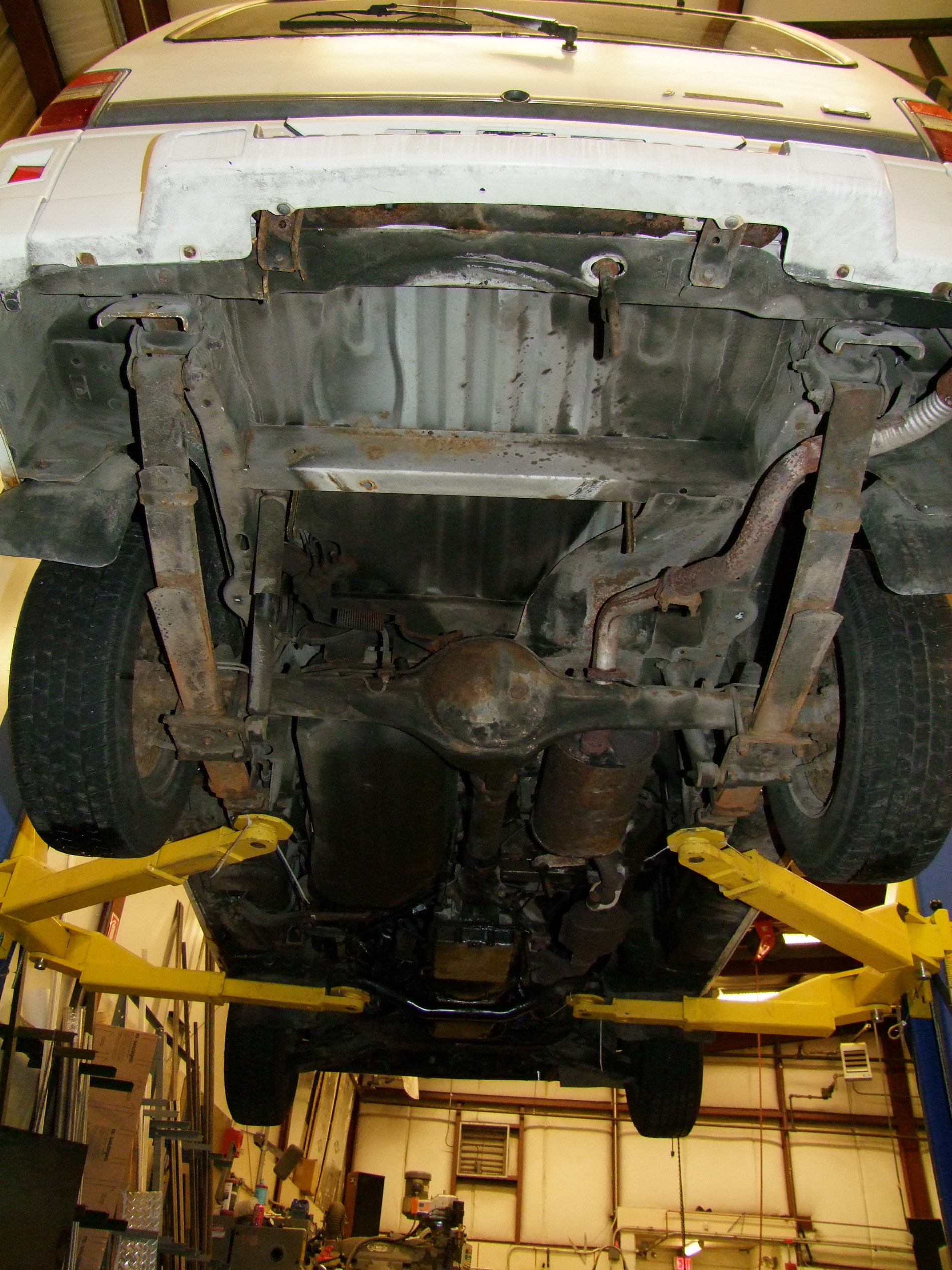
(It’s also the only spot on the underside that isn’t covered in filth.)

This spot seemed to be begging for a weird action movie attachment to be installed in it. It’s located very close to the rear axle, so I wouldn’t need to build in tons of compliance and “suspension” travel. It’s out of the way of the possible design and manufacturing exercise up front. And parallel frame rails.

The only downside I could see was that I might want to hide the Siemens motor in that spot some day, but I think by that point I’ll have a justifiable reason to leave it on the lift for a little while. That, or give it a nosewheel.

The dimensions were also pretty handsome:

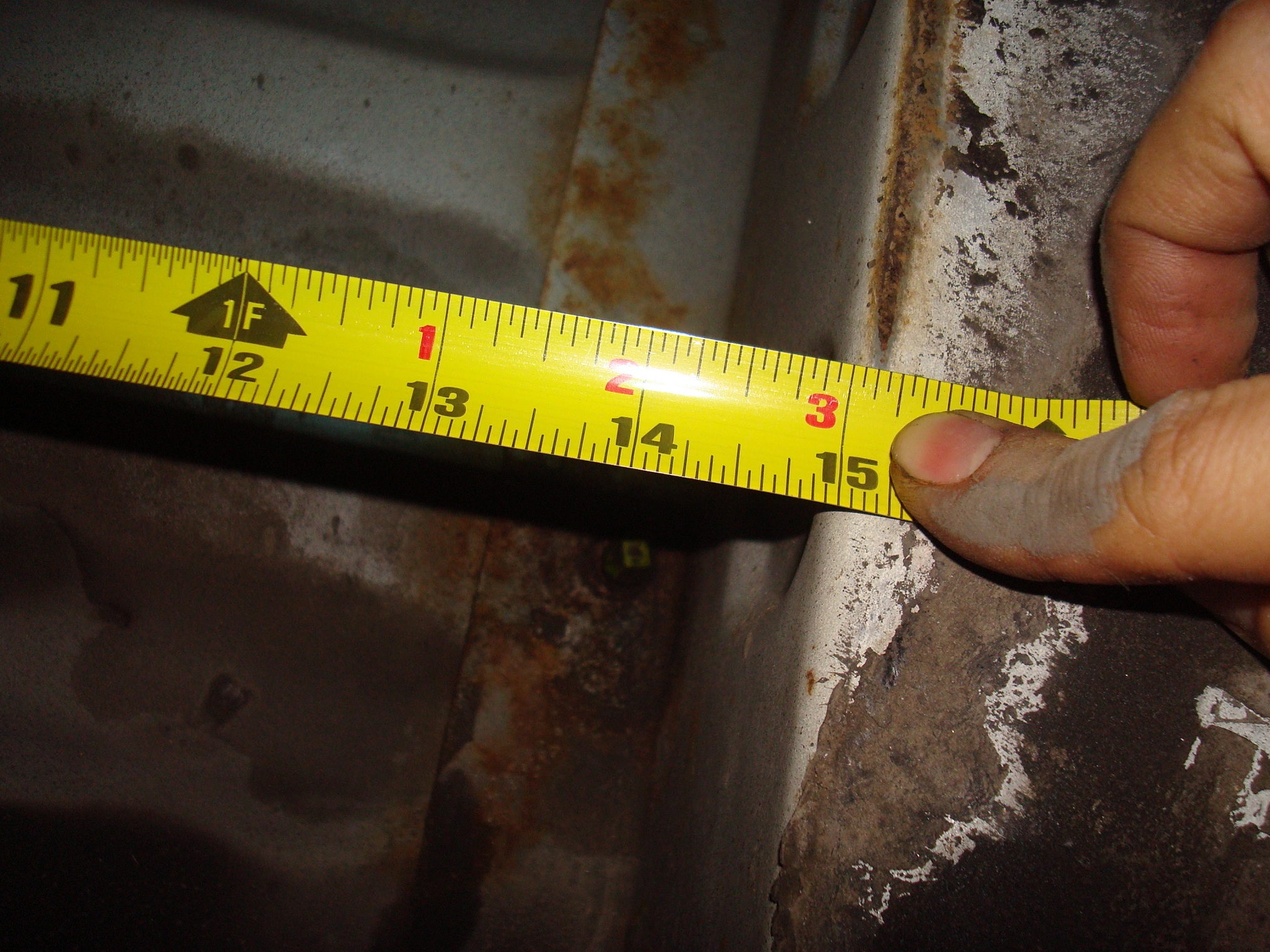
The width between the rails was 15″, with another 10″ ahead of that before the rear differential bulb. The rail depth was about 3″ and the distance from the underside of the floorpan to the ground, with the vehicle parked on a level surface, is 18″. Width was pretty much arbitrary.

the mechanism

I spent a while musing about what kind of mechanism to mount everything with, and how to attach it to the frame. I didn’t want to weld anything in (making it permanent, at least from my traditionally welding-free building methods), and wanted to avoid drilling and bolting if at all possible.

Not knowing how strong the spot welds holding everything together actually are, I decided to pursue a jacking type of attachment. The structure of this device would push itself against the two frame rails hopefully with enough strength to resist the loads of the motor cranking on it. This was going to have to be a very strongly braced connection, since I’m basically mounting a fetal twin EV to the underside.

If it turned out that I was going to pop welds or bend sheet metal, I would just bail out to drilling and bolting using blind insert rivet nuts into the frame rails.

I began by hopping into Inventor and sketching out what would basically be going on:

I made the basic mechanism in a sketch, first using lines only (or just the essential “bones” of the mechanism), then fattening it up with representative motors and wheels. In this graphic, the big circle is the 11″ go-kart wheel and the smaller circle is the D&D motor.

At this point I’d basically settled on making most of this contraption from welded steel tubing. My usual modus faciendi is to waterjet-cut some plates and throw them together, but I’m guessing that the majority of fabrication on the final vehicle – motor mounts, battery boxes, additional structures, etc. – will be welded, manipulated steel sheet and plate joined to tubing, so what better than to practice?

The mechanism of raising and lowering is an extremely simple single-swingarm, almost like a motorcycle rear end, with what would be a “shock absorber” in a real vehicle application being an adjustable leadscrew. That way I can crank the wheel down and continue loading it against the ground to take weight off the rear axle.

And this mechanism in the lowered position.

With the basic mechanism loaded in my head, I started embodying it in 3D. This is the tube structure that will be welded up. 2″ square tube make up the swingarm, 1″ square and 1×3 rectangular make up the framework. All 1/8″ and 0.1″ wall – in other words, 1,000x more heavy duty than the van itself. I’m fine with that – this shit is cheap.

Using the 2D sketch mechanism info, I transferred mounting holes to the 3D model. The four holes are mounts for some beefy pillow blocks to hold the wheel driveshaft and the intermediate shaft needed to complete the 8:1 mechanism in two stages (I can’t achieve that in 1 stage without going to ridiculous sprocket sizes)

I’ve moved onto adding models of the D&D motor and wheel. The dimensions are obtained from calipering the real world items.

Added pillow block models and also one idea for performing the frame jacking. The pillow blocks are giant cast iron jobs from Surplus Center – maximum cheapness per bearing.

The jacks are giant turnbuckles used in reverse to provide compression force. But wait, aren’t turnbuckles only designed to add tension to a system? Yes, hence the hugeness. The long skinny sides of turnbuckles make them ill-suited to pushing against a load – they’d rather buckle apart. I figured that making them enormous would mitigate this issue for the clamping forces I’d need. These are 10,000 lb turnbuckles from McMaster, who fortunately pried a CAD model from the legacy U.S. company that is making them so I did not have to drop $70 to find out otherwise.

I wasn’t too set on the returnbuckle idea, but for the time being I settled on the rest of the mechanism and assumed a jacking method will exist.

Turning my attention to the leadscrew linkage, here’s some shots of the trunion design. The trunions will be made of some chopped up 1.5″ diameter steel tubing with welded endcaps. The nut in the center there is a standard 3/4″ Acme steel nut, the kind you use to hold steam valves together, and again purchasable on Surplus Center for a guava and two potatoes.

The underside is where it gets a little interesting. So here’s what’s going on – As the wheel contacts the ground, the blue spring will compress with every further turn of the leadscrew, adding “preload force” down on the wheel. If the wheel hits a pothole or something, or I drive off the entrance ramp, it can dip town and maintain traction, avoiding awkward fake burnouts.

If I need to crank the wheel back up, then the J-shaped hook applies pressure to the backside of the swingarm trunion (the long round tube in the center) and so the whole assembly can float back up. When the spring is compressed, the hook moves away from the trunion a little.

What this doesn’t do is add upwards compliance, say a speed bump or armadillo in the road (because Cambridge has a wild armadillo infestation issue – ask any long time resident). However, the path I intend to take is pretty free of obtuse bumps. If the wheel hits an obtuse obstacle, the forces should be transmitted handily into the ladder frame. Should be. Those insert nuts are looking delicious right about now.

I knew coming back to the previously handwaved mechanism would make me smack myself for even thinking of it. Here is a new jack design made only of welded tube, threaded rod, and nuts. $150 cheaper and probably less shady. The forward (right side in the image) bar is free to move in and out of the tubes, kept from moving in only by the two nuts jamming against the tubes. If I need to expand the width, then I just crank on the two nuts.

This design was frozen after a few days of not looking at it, during which I instead watched the Singaporean students try to design kart drivetrains using 4,000 RPM/V motors. Which, mind you, is totally possible if you don’t mind using a 100:1 gearbox or something, but your handling could suffer.

construction begin

Here’s the pile of big parts as of last week. Motor, sprockets, bearings, a bunch of related hardware…

…and this pile of steel, primarily foraged but also ordered from Speedy Metals. The huge shafting, in 3/4″ and 1 1/4″ sizes, came from Surplus Center to match the bearings.

Why such huge shafting? It’s because as it turns out, 1 1/4″ is a standard American go-kart wheel axle diameter. I found a cheap hub on eBay which matched the wheel perfectly and converted it to a 1 1/4″ shaft.

I’m guessing the 32mm standard size is the Irritatingly Close But No metric size for the same application.

I also tried something a little different sprocket-wise this time. I normally waterjet my own sprocket profiles, but with the assemble-from-COTS-parts mantra of this build, adapting them to the drive shafting would have meant that custom flat plate sprockets were pointless. Instead, why not buy commercial flat plate sprockets? From Surplus Center, large sprockets get cheaper as you move to these “welded hub” versions. For $20, you can basically have any sprocket size and hub bore/feature combination. The final output sprocket, of 50 teeth, gets the huge 1 1/4″ keyed bore, and the smaller intermediate sprocket will ride on a 3/4″ keyed shaft.

I’m going to spare the welders the pain of seeing my handiwork, but let’s just say that “MIG-over-TIG” was an acceptable ditch plan. It’s often said that in TIG welding, the best welds look like a stack of coins. Mine look somewhere closer to a stack of rabbit droppings (Part of the problem, as I remembered/was reminded, was that I was trying to weld these sections using a 100 amp TIG welder and a tungsten too small to even take that current).

With the parts buffered and ready, it’s time to attack the structure itself. There’s much welding metallic gluing ahead; the next post will focus on the construction of the structure and machining all the little round things that go into it.

In typical fashion, I spent a few minutes thinking of ways to name it as close to an Internet meme as possible, and the result is Detachable Electric Rear Powerdrive , or DERPDrive for short. I wish everyone the best while facepalming.

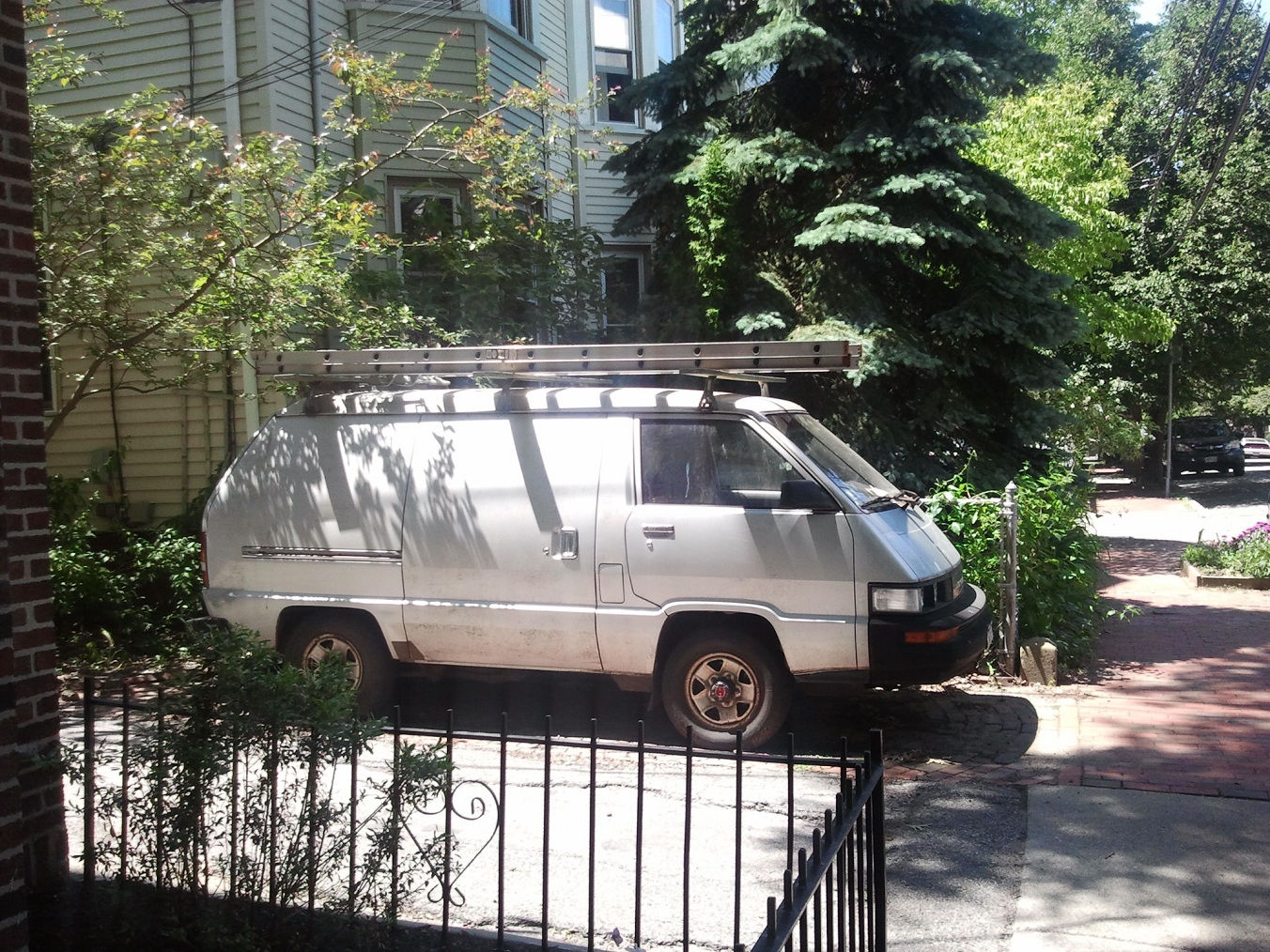
Also, I found a nice sample of first Legendary Derpy Van, the Toyota Van, while cruising through Cambridge back streets avoiding traffic one day. If only vans were like dogs or guinea pigs.

Loose Odds and Ends from the Past Week or so

Things have been getting exciting in the last week or so as the SUTD Summerkarts Global Leadership Program students have arrived, and we’re now well under way into the Silly Vehicle design phase all over again. Global Leadership Program. That’s such an epic name for 2.00gokart, guys. To be fair, there’s plenty of other things going on for the students too, most of which are ‘leadership’ flavored. In this running of the class, since I’m not being watched over by The Department and need to make sure everyone has paper lab notebooks, the student groups will be blogging their builds! I’ll post a list of links once everyone gets set up.

mikuvan

I’m currently at 380 miles.

Having essentially reached the limit of things that have been going wrong, I’ve been faced with no choice but to start attacking rust. This thing hasn’t even so much as hiccuped a single time since Operation: Bad Timing. I would say that at this moment, having checked everything I think is important, I’d trust a trip out to at least New York City (about 240  miles).

I’ve mostly been spending the past 2 weeks psyching myself out and picking up some materials.


Based on estimating the clooooouuuuuud Internet and asking friends, I got a pile of things from Eastwood – panel sheets, a bucket of sealer, and some rust converter. I was skeptical about the “rust converter” – it allegedly converts iron oxide (“rust”) to iron phosphate or iron tannate, which is some shit I’ve never heard of and only appears in product descriptions plagiarized from Wikipedia. This sounded shady, and success seems to be hit or miss. However, it’s relatively cheap, so we’ll see what this magical potion does. That, plus another haul of random abrasive and sheet metal banging tools from Harbor Freight, ought to round out the basic non-sketchy rust patch. I’m going to try the pound-and-weld-metal route – falling short of soldering since it sounds a tad too hardcore at the moment – instead of throwing fiberglass at it.

All that, and waiting for several days of hot and dry weather to do the majority of the work, just to smoke out any residual moisture from the body holes. Recently, it’s actually been hard to come by, with the Northeast in its Periodic Random-Ass Storm Season (PRASS). There’s no point in tying a puddle up inside my work. Worse come to worst, I’ll point a space heater at the trouble spots for a day before doing anything.

What I’ll do first is probably do all the sanding and grinding; the full-depth investigation, basically, and then post it publicly to get some opinions and appraisals. The idea is to cut or grind off what I can get to, covert and cover over what I can’t abrade off, and then slather external underbody repairs in sealing compound. I also managed to find a matching Chrysler color at Advance Auto Parts to repair the exterior paint afterwards, tested by blasting random areas and staring at it a few minutes later. This may backfire horribly.

Part of the reason I’m hesitant to start is because I have the feeling that things will get more and more Death Race 3000 if I mess something up or discover more structurally unsound areas than I previous anticipated. What you can’t see….

Though, in the limit of Death Race 3000 style modifications, this thing will probably look more and more like a classic wedgebot.

testing the mini-jasontroller

I replaced the full-size caseless Jasontroller in RazEr REV2 with the mini version detailed last week.. I’m definitely a big fan of these now – they’re basically the same as the full size, in a much more useful package.

This is the smaller controller uncased and fully cleaned. I essentially took out every wire I didn’t need, and also locked the speed setting to high internally by jumping the right side orange wire; by default, the “3 speed range” switch comes in the medium range, which means it divides down the throttle input) This has no bearing on its upper speed limit which is still around 540-550 eHz or so, but for low speed motors the throttle response will be substantially retarded otherwise.

These controllers have a discrete logic power switch, unlike the full size Jasontroller, so I also hardwired that internally (left).

I discovered that the entire controller case fit inside the space where my old full size Jasontroller went, minus one corner. So, instead of redrilling the mounting holes for the smaller heat spreader bar, I cut the entire case into an L shape with the board resting in its stock location…

…shrink wrapped the whole thing, and Velcro-mounted it in. Clean and waterproof, and the additional aluminum should still offer some thermal capacity.

The overall height of the controller when stripped of its case is under 0.8″ (in my configuration, it’s not much shorter due to the existing case outline remainder), which opens up the potential to be stuffed into even more things.

I’ve noticed no difference in riding behavior between the mini-Jasontroller and full size, once again confirming they’re basically the same thing. I’ve noticed some slight difference in starting behavior – the mini doesn’t twitch backwards, at least not often. More observation will be needed to discern the differences. In the mean time, I’m officially qualifying the mini-Jasontroller as Certified Legit. You can buy it on this page, and maybe soon from Equals Zero. If you make something using one, post it!

I’ve added this controller to my Scooter Instructable in the EV controllers section.

more silly rideable things

One of the downsides of having 160 cubic feet of self-motive cargo volume is Oh man, this free stuff on Craigslist looks awesome. I’ve previously been limited by what I felt like carrying back on Melonscooter, or worst case, ride back independently. That’s no more.

What you see here is a most-relevant-to-my-interests free Craigslist haul of two nonfunctional electric bike (-like-objects) from a closing e-bike shop. The one on top, as it turned out, is quite the machine. It’s a TidalForce IO cruiser bike, from another one of those small EV companies with an illustrious but ultimately short lived existence, in complete condition. The bottom red pile is a generic Chinese “电动车” or “Chinese moped”. These are sold here and there under various names (here’s one example, and most likely the company that retailed it since it says GREENPOWER on it!). Its condition was a little more beat up, but seemingly just devoid of batteries.

Here’s a better shot of both of them. Being me, I’m actually more a fan of the little red moped – it’s a little weirder and has that Chinese charm to it, but the Tidalforce was much more complete, so I began messing with it first.

The backstory of this machine was that the customer dropped it off for battery service and abandoned it. Apparently, these bikes were notorious for having their NiMH cells degrade very quickly.

Lacking a legitimate charger, I jacked it in on a power supply to 45 volts CV and fed it at about 0.8 amps for basically the better part of a day. The cells inside are nominally 8Ah, so the charge rate is a nice C/10 trickle charge. In case any of the cells were permanently toast, it wouldn’t cause thermal runaway. The battery came off nice and warm, and I rode around until the bike shut down from undervoltage. This charge lasted basically 5 miles with very little pedaling. The original advertised range was 15 or 20, but according to the storytellers realistically 6 or 8 miles, so it didn’t seem that far off the mark.

The termination condition is dictated by the battery management system onboard, and this is where things got difficult. No matter what, I couldn’t convince the charge-o-meter to go above 20%, even when I’ve clearly left the battery on slow trickle for many hours! I suspected that this artificial BMS meddling is what shut the bike down in the first place, since it didn’t feel like it was about to slow down.

I did some research online and came upon this useful page for decyphering the onboard controller for the bike, as well as this flamewar thread on Endless Sphere where someone mentioned that the battery needs to be discharged to under 32v to resynchronize the charge indicator.

This battery is too damned smart. I couldn’t get any output voltage from it unless the bike was on, since it has internal FET switches to shut off the cells from the pack output, so I couldn’t artificially drain it. And even at 44 volts off the charger, I couldn’t get the bike to move more than a couple dozen feet before the BMS shut me down. I hate it when batteries are too smart – I’m forced to crack them open.

Off the front wheel comes. It’s on a quick release, so a latch and some cable pulling later and it comes cleanly off.

Removing the case screws and side, check out this holeaphobia-inducing lotus flower of cells! The terminals all had bits of corrosion on them, but there were no signs of leakage that I could observe.

Hammering on the opposite side of the wheel makes the entire battery structure fall out. This is the important side of things – the BMS board. My mission was to artificially brick the pack via the CELL tabs, draining them to under 32 volts, hoping the BMS would reset or something.

I used this shady arrangement of power resistors, totalling 15 ohms, to drain down the pack over the course of about 3 hours, getting the whole array down to about 30v. Afterwards, I immediately closed everything up and threw it back on the charger. It did exactly jack shit.

The battery meter blinked 20% the whole time! I’m going to guess I did this wrong somehow, or more likely, forgot that Ni batteries bounce back in voltage very well after an initial discharge. By the time I was done connecting things back up, the battery voltage could have been well in excess of 32v, making the BMS think everything was still skullfucked. But it should at least recognize the 7Ah I dumped back into the battery, right?! No such deal.

As of now, I’m currently riding this thing around day to day to burn down the charge in a useful fashion. Apparently, the charge meter blinks in its entirety when the BMS reset point is reached, so I’ll hopefully be ready then.

Why am I trying so hard to use this proprietary-ass stock battery when I could very well just hack the “B” battery with any number of potential long running packs? I’m hesitant to do that because I don’t actually like this thing. It weighs nearly 60 pounds and is enormous, clearly built for a much Manlier Man than I. Plus, I can barely stuff it inside my front door. I guess I’m used to smaller and more portable scooters which can be rolled inside – this sucker is going to need the bike rack. Not really my style.

For now, though, it’s alive and working as yet another Craigslist impulse that turned out to be a little neurotic but otherwise livable day to day. What’s with me and that kind of thing lately?

Let’s move onto the Little Red Moped.

After diddling around with the TidalForce for a few days, I decided one night to get this contraption running along with Adam. I cleaned up the mechanicals and repaired the existing wiring while he created an impromptu brick of 12V7 modules I have on standby for the summer EV design class.

Look at that beautiful… 20 gauge? wire going to the hub motor! This machine is capable of Real Power.  The hub motor appears to be a 48v, 500W (or 750W) brushless type, like this.

Unhitching the electronics box, I discover this wad of wires. If you ever wonder what Jasontrollers and their ilk are actually used for, this is the answer. As you are reading, millions of Asian moped bros are cruising about on machines exactly like this one.

During my wiring cleanup, I found a spider!

Someone clearly was derping around with this after-market and the controller is likely not the original. Someone was also terrible at this. There were plenty of examples of wires just twisted together and electrical taped up, and solder joints like that.

Whatever. It worked, and all I really did was replace some of the decomposing electrical tape and resplice some of the signal wires appropriately.

With the impromptu 48v battery and a random found bike seat, it was ready to roll!  And roll it did. The acceleration was brisk and utilitarian, and the suspension was a bit underdamped but compliant even when riding up curbs. It’s very quiet, and there’s a pedal assist sensor which almost sent me into the wall a few times when I instinctively kicked the pedal out of the way.

Riding it in this form makes me envision myself wearing a straw hat and dark brown Mao suit, riding along a dusty Chinese road to my factory job. With a cage of chickens on the back to be sold at the market later that day.

We agreed it would be more amusing once completely rewired and running on 72 volts, but sadly, Mao’s Little Red Moped did not see that day. For at Swapfest, I was riding around aimlessly for no more than 10 minutes before someone bought it off me on the spot. Sans batteries, but still.

So my net wheel gain for the past few weeks has been 2, both won by the TidalForce bike. Unfortunately, that may increase again, because I’m considering…

a playmate for mikuvan

Your job, Internet, as the guardians to my sanity, is to tell me I do not need another one of these.

Let’s face it. I was originally looking for a science project with Mikuvan, but elected to put in an honest repair effort to have me some of that thar “auto tech” larnin’ y’all kids are into these days. But now it’s running too well, and a few of us are basically invested emotionally in it, and I have a harder time with the thought of tearing everything down again than when it wasn’t running.

Mere weeks after I stated my life goal Passive Non-Career-Derailing Desire was to collect the Legendary Van Trifecta, I discover that I might have a chance to nab the rarest of them all: the USDM Nissan Vanette. Yes, the one which was well known for lighting on fire.

The back story for this find is quite circuitous indeed. It wasn’t by weeks of stalking Craigslist, or a “Hey, I hear you like derpy vans” referral from my “Hey, I heard you like trashy electric scooters” network. Instead, while doing research on the other members of the trifecta, I found this Jalopnik post for a Nissan Van (-shaped-object) in North Carolina. Some link hunting led me to the original sellers album…from 2011.  Out of sheer shits and giggles morbid curiosity, I emailed the seller what amounted to “lol do you still have this”. MFW the answer was yes:

I’m at a loss about what to do.

On the one hand… Whoa, a chance to capture the rarest Legendary Pokévan and train it make it the base for this electric drive project. After all, the way the world apparently works, as I’ve handily found out in the past few months, is you have a functioning car, then you get an explicitly nonfunctional one to mess around with. This van is so explicitly nonrunning the FCC and ASE are about to join forces to erase it from reality. The chassis mechanicals appear to be comparatively rust free (then again, so I thought with Mikuvan).

The downside? Space. Parking. Not even counting the (once yearly) cost of registration and (fairly low) monthly insurance premiums once it’s operational, there’s no such thing as a little empty grassy patch to stick a nonrunning vehicle here. I was lucky with Mikuvan that my one allotted parking spot was open. What I cannot justify is paying hundreds of dollars a month for a parking spot or garage space for a van-shaped lump without the knowledge that I will immediately be able to attend to it, rare or not.  I’m currently in the process of exercising my social network™ to see if anyone is willing to put up with my bullshit. Ideally, there’s a back alley of a nearby industrial space somewhere that I can slip into, or someone’s back yard who thinks this is all too hilarious. I’m not going to try very hard.

So the dilemma goes. I will probably not see one of these in such a complete condition for many years, but maybe in said years I’d be in a better position to start Big Chuck’s Van Adoption Service.

 (All pictures above of the vehicle were provided by the seller)

I’m filing this post also under Beyond Unboxing since so many things were taken apart in one way or another.