BurnoutChibi’s Steering and Braking

In the past week, I’ve been managing to intersperse bits of BurnoutChibi work between hosting extra hours for the 2.00gokart students as they edge ever more towards completion. On Wednesday, the “Milestone 7” mechanical inspection occurred, where everyone had to demonstrate their rolling frames with steering and braking. The next steps for the students from here are focused entirely on assembling their electrical system. In fact, two teams have already blitzed their vehicles to completion, and more are surely to follow (parading them around during CPW is a huge motivator). I’m going to make a separate post about the progress of the class later – all I can say for right now is that this year’s competition is going to be awesome.

The first thing I had to do to build a new Chibikart is to disassemble the old Chibikart. Here’s the scene of the crime:

This work left me with a pile of redundant electricals – namely 4 more Jasontrollers and the massive A123 B456 battery. Needless to say, these will probably find their way into some other silly rideable thing.

The plan for BurnoutChibi’s electrical system is actually to use my left over 10S 5Ah lithium polymer packs, instead of making a custom pack or keeping the A123 pack. I decided to this mostly for the power and energy density of the lithium polymer packs (Chibikart 1 weighed 53 pounds because the big A123 bus battery module weighs almost 20!)  as well as the simple fact that said lipo packs have been sitting for almost 2 years, and I really don’t want to see them go to waste. The lipos themselves are from the erstwhile Deathcopter, so BurnoutChibi will surely be the health and well being hazard I envisioned it to be.

The first appendage to the old frame is the new style brake pedal. At this point, I haven’t even removed the old steering linkage yet, but I wanted to see if it would interfere with the new position of said linkage.

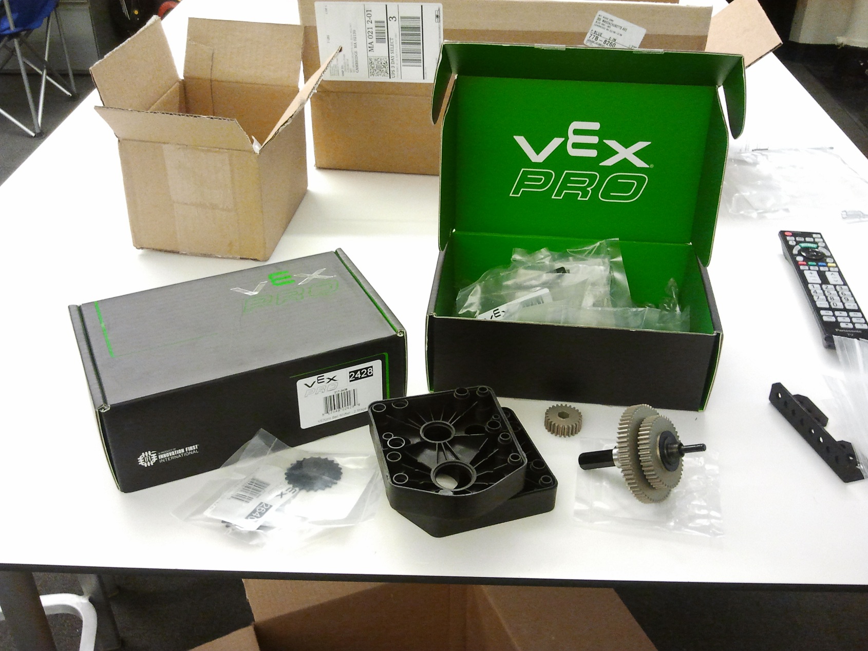
I started from the rear with fitting the Vex Ball-shitter transmissions onto the “goalpost” mounts. This whole ‘rebuild’ is essentially replacing Chibikart 1 frame plates with specially crafted DPRC ones. The only difference between this rear corner and DPRC’s is the goalposts!

I focused on getting the motors mounted and the rear end together. Here, I’ve mounted the NTM motors to my NTM-to-CIM converter plates. Eliminating units, the result of this evaluation is something which is basically like a CIM, but 4 times more power dense.

There’s only one problem. The NTM shafts need to have a 2mm keyway cut into them so I can easily used the keyed bore supplied with most FIRST OEM parts such as the Vex transmissions (The fact that I can say “FIRST OEM” is unsettling).

As it turned out, these shafts are casehardened. Wow, Hobbyking, you’re classy now – what this meant was I could not use my single HSS 2mm endmill to machine the slot. Instead, I went on eBay a few weeks ago and bought some 2mm solid carbide endmills. I recommend keeping a set of carbide cutters around for dealing with troublesome materials; the downside, of course, is that they are more brittle and need a stiffer machine setup.

I faced the slight issue of the endmill being too short and the Bridgeport spindle being too fat to reach the nether regions of the  motor. So I did what any self-professed machinist wouldn’t do, and chucked it up in a drill chuck. In my defense, I bought this integral-shank keyless chuck just to do dumb things like this.

I cut the keyway just a little short of actual dimensions because the NTM shafts were not long enough to use the included retaining ring with the gears. So I had to press the key in,and will need some creative gear pulling if I ever wanted to remove these gears.

And here they are mounted. I found the sheer number of hexagonal sockets on the gearcases a bit confusing at first, but now appreciate how versatile they can be.  Chain tension is adjustable using the slightly slotted mounting holes. I inserted locknuts (nylocks) into the opposite side hex sockets, so torque retention will be positive.

Notice how the seat mounts have been turned around. This was necessary because of how big the gearcases were. The seat mounting centers, and overall position, will remain unchanged.

Crawling up the side of the vehicle, I reached this build’s star attraction: The gear shifter. This came together amazingly well, and the feel of the ball detent plungers is extremely satisfying.

Heading up front, I popped out these new steering knuckles. In keeping with the tradition of doing the least possible work, these were specifically designed as drilling operations in a 1″ aluminum square barstock. The four flange holes will be where the drum brake mounts.

Continuing work on the front end, the drum brake mount has been attached and the new narrower steering…ears? are mounted. I’m not sure what to call them on Chibikart. They’re too short to be A-arms or wishbones.

Recall the new steering linkage arrangement – the crank arms are basically socket wrenches that fit over the hex head bolts. Motion is transmitted via giant set screw in the steering knuckle. To ensure positive engagement, I machined a deep flat into the hex head bolt shanks and picked flat-bottom set screws to maximize the contact area. To retain the crank arms, I center drilled a hole and threaded it for a retainment bolt. Otherwise, the crank arm is thinner than the bolt head and will be free to float about 1/16″ or so.

I moved on to chopping up the 90mm drum brake to fit up front. The mounting method I ended up devising would have been fine with keeping the giant torque arm, but the design would be cleaner without.

To maintain the cleanest possible lines, I brutally slashed the housing with a Dremel cutting wheel.

To attach the drum brake itself to its mount, I first had to machine the little round spacer which adapted the 14mm bore of the brake housing to my 1/2″ bolt wheel spindles. I sandwiched the brake housing between the mounting bracket and the spacer so it was reasonably centered. Next, it was a quick drill press job using the mounting bracket holes as a drill template. The steel housing on these brakes is just thick enough to hold a few threads of #10-32, so a socket cap screw was screwed directly into it through a standoff.

The mounting bracket itself involve one sheet metal bend to create a spot which will eventually anchor the brake cable. Well, I managed to bend it the wrong way the first time. Heating up the aluminum with a torch and carefully bending it back the other way worked, but the metal still cracked on one side. I had a buddy on MIT FSAE lay a quick TIG bead across it (see the irregular texture where the sheet metal arm bends left).

The brake drum mounting itself is what I’d call “kinematically suboptimal” very nicely. Basically I squished the slightly tapered stamping flat on a hydraulic press to get a flush mounting face on the bottom side. Then, two standoffs which each have a small shoulder that is precisely fitted to a mounting hole keep the drum attached to the wheel. On the top side, the standoffs have a 1/4″20 thread so I can use already available button head screws to retain the rotor. On the other side, the standoff is tapped M6 X 1 to interface with the original wheel lugs bolts.

The concentricity, needless to say, is less than stellar, but turned out way better than I had anticipated. I’m likely to replace this whole rig with a custom machined aluminum dish that has M6 x 1 holes tapped into it so I can just dismount the whole tire without causing loss of alignment. The brake does scrub, but only slightly and intermittently, and works very well otherwise. I have no doubt that this thing can lock up and skid.

And the front end is basically together.

Work now will move to the rear again with assembling the drive wheels and sprockets. I have an order of brake cables and associated parts coming, so I hope hooking up the whole drivetrain and shifter this week is a possibility.

The Secret of BurnoutChibi

Continuing on my last post, I’ll talk a bit about how Chibikart is getting a radical design departure from my usual silly vehicles, and later on some about what the hell I’ve been up to for the past week or so. These days, like last spring, my time during the day is heavily  devoted towards herding 2.007 students in some way, including my own “victory garden” of 2.00gokart students who have seemingly become accustomed (read: spoiled) to work late into the night like I do. I’m clearly being the best of influences for my impressionable undergraduates. With my spare time being more fragmented and less conducive to sustained building, I’ve been revisiting some things which I’ve mentally tucked away for better days.

Anyways, to recap, BurnoutChibi is my proposed refitting of the Chibikart 1 frame, which is currently sitting derelict waiting for motors I will never regain the patience to rewind, to a form which offers some more excitement. The reason for the upgrade is twofold – first, I’d like to bring it up to “Chibi 2” standards, but more importantly, to up the power and show how an inexpensive sensorless drivetrain should be executed. The last time I showed the design, it was a simple one-stage design that was basically the DPRC with more power, and pneumatic wheels.

As I was designing the drivetrain reduction ratios, I began thinking more and more that having 1 speed, even in an electric vehicle, is just suboptimal. With the power levels that the selected drives were capable of, I could reach about 18mph and smoke some rear tires. But that would be it – the fastest it would ever go would be said 18mph. Yet just power-for-power alone – power dissipated by air resistance at speed versus the mechanical power produced by the motors at 50% load – the drives have enough punch to get me to nearly 40 miles an hour. If I were to gear for that speed, it would accelerate very… gently. And that’s only in the ideal case of the motors being able to sustain the high current draws needed to produce enough torque to get there.  Regular permanent magnet brushless motors are really quite limited in the ranges of speeds and torques they can achieve alone.

I’ve wanted to build a multi-speed vehicle for a while, because it still just seems like a better idea. You can shift the peak power and efficiency speeds around depending on your load requirements. Recalling Ben’s successful über-trike build pushed me even more towards that direction – that thing actually has 8 speeds using a bicycle hub gearset as the transmission. I was interested in even having two – burnout mode, and do-more-interesting-things mode.

It was easy enough for me to cook up a custom “shifter” design, but what better opportunity again to test out new parts on the market? Once again, I turned to Vex Pro for the answer. I’ve been eyeing their “ball shifter” (which sounds somewhat painful) transmissions since they were put up on the website.

Many a drivetrain in FIRST have been built using the classic AndyMark shifter transmissions, ever since the drill transmissions went out of style, and AM was the first place I went to when I was looking for COTS 2-speed options. What I didn’t like about them (both now, and years ago in FIRST) was how huge they were. The large, open frame sheet metal design is easy to manufacture, I’m sure, but there was no way I would have stuffed one onto this frame.

The new VEX transmissions seemed to be better packaged, and used a much more compact shifting mechanism. Inside its hollow shaft is another shaft with a round lobe on it that can slide axially. It pushes out on one of two sets of steel balls seated in the outer shaft, overall resembling a rachet wrench’s ball detent. So, depending on where the lobed shaft is pulled, a different set of balls is pushed outwards, acting like a 3-point spline. The output gears have little cavities that the balls lock into. If the lobe is not present under that set of gears, the rotation of the gear on the shaft will naturally shove the balls back towards the center. Pretty nifty.

Seeing no obvious complaints on the FIRST grapevine about them, I’m assuming they’re working pretty well for the competition and are robust enough to shuffle some 120 pound wimpy robots around. But can they stand up to moving a Chibikart at inadvisable speeds, while transmitting enough torque to break traction on asphalt?

I had my doubts – the ball shifting solution seemed like a great alternative to the AM Shifters’ dog clutches, but I trusted the metal-on-metal pushing of the dog clutches far more. Primarily because the dog clutches transmit torque at a greater radius – such that the stresses in the materials are much lower for the same level of torque transmission; and that the engagement is extremely binary – either engaged, or not. The ball shifters seemed to have a much greater potential of being caught “between gears” if one or more balls don’t release.  But maybe that is just a problem if I push so much power through them the ball detents deform.  I was already aware that shifting under power was basically out of the question – there’s no synchromesh devices on any of these things, and even in a real manual transmission car you wouldn’t hold the throttle down while shifting gears anyway.

So, with this many questions about whether the part would be worth anything, it was clear that I was going to have to get myself a set of Vexboxen. Because if nobody in FIRST is going to break them, I might as well.

Or, hold on… time to get myself another set of Vexboxen. I already have a VersaPlanetary that I’ve dissected and taken pictures of and am still waiting on a reason to do a Beyond Unboxing post on – they’re quire nice pieces of kit.

I downloaded the CAD model of the whole gearbox off the Vex website and immediately started cutting it up. First off, nothing was constrained – the solids just floated around, the constraints being broken by the export to a generic format. So I spent half an hour “reassembling” all the gearbox parts.

Next, I removed everything I didn’t care about – namely, all the hardware and the encoder mounting stuff. And the pneumatic cylinder that is supposed to run the shifting shaft. I was intending to cook up a mechanical linkage of some sort, since I didn’t want an air system on this build, no matter how air actuated brakes would have been.

I replaced the CIM motor with my NTM 5060 model using an adapter plate that will be machined. Both motors have an 8mm shaft, so interfacing with the supplied gears shouldn’t be an issue. I took the opportunity to raid eBay of some 2mm endmills to make the keyway in the NTM motors.

A quick fit test to the frame and… My goodness these things are huge. Luckily, when mounted upside down, the resultant sprocket spacing was acceptable.

Notice how these gearboxes are all designed for 2 CIM motors. I have no qualms, if this experiment is successful, of dropping 4 NTMs on this thing and upping my motor sprocket size for even more ludicrous performance.

I flowed some virtual metal around the mounting points to generate these two-pronged mounting adapters. The big gap in the middle means I can still access all the important motor mounting screws. Else, these gearboxes did not seem to require any other additional mounting – even the Vex website just recommended using their stock L-bracket mount.

The output shaft being a Hex of Convenience and Marketing Exclusivity, I decided to just get a 22 tooth hex-bore sprocket from Vex. Okay, Vex, you win this time.

The final drive ratios for each speed, then, are 18.17:1 in low gear and 8:1 in high, for a resultant speed of only 14mph in low gear and 31mph in high. I would have preferred a speed spread of less than 2.0x with a wider low gear, but hey, that’s what I get for not designing the thing. But the extra-tall low gear will definitely prove my hypothesis that sensorless drives can be successful if they are highly geared.

To actuate the gearbox, I needed a mechanical hookup. I was concerned with how much force the shifter shaft needed to operate – the installed shifting mechanism is a small pneumatic cylinder that is capable of nearly 30 pounds of static pull. Clearly this was not required for operation, because that would be ridiculous. After studying the mechanism in CAD more, I determined that it really should not take much force to actuate if I am not applying power at the same time. The actuation method would just need to be very fast to prevent the balls from skipping slot to slot.

I briefly entertained electronic shifting using big solenoids. The required travel was only 1/2″, which is well within the range of big open frame solenoids I could find for cheap. What drove me away from that was finding said solenoid that had a continuous power dissipation rating. Generally, industrial solenoids are rated for only 10% or 20% duty cycle – in other words, 1 minute on then 9 minutes off is 10% duty cycle. More frequently, the “maximum on time” is also specified, usually also 1 minute. Even though electric shifting would likely have been quicker and only required a button instead of running linkages or cables, I was more into the visceral mechanical solution and not particularly interested in cooking solenoids.

I elected to use a spring-balanced cable sort of mechanism with 10 pounds of return force to shove the shifter back into the starting gear. Luckily for me, the lowest gear was associated with the innermost position of the shifter shaft. So, it was easy to find a spring on McMaster-Carr which qualified for the needed return force at the needed stroke (about 1/2″).

What I could not do was find one which also worked with the dimensions of their included shifter coupler. The black object in the center of the gearbox between itself and the standoff-mounted plate is my own quickly whipped up coupler design, which let me fit a spring (not shown in image) between it and the rightmost black flanged doobob. This spring will try to keep the gearbox in 1st gear, so long as I am not tugging on the cable to keep it in second gear.

Some cable adjustment will be needed for sure to ensure synchronization of shifting.

On the other end of things, I put together a simple lever using mostly McMasterables. Did you know McMaster sold random knobs and levers? Now you do. Oh, and little ball detents already loaded into threaded bodies. Super simple instant two-click gear shifter!

This and many other reason are why, this coming Dragon*Con, I am hosting a panel session on how to shop on McMaster, among other places.

Time to mince some metal soon! I ordered this stuff last week. I have yet to assemble the gearboxes, but they seem legit. The casing is heavy fiber reinforced nylon (or fiber reinforced something or other), and the gears are… sticky. Seriously, whatever magic coating they put on these things, it straight up sticks to my hand. Repeatedly, even. I can flat-palm a big gear and lift it straight up off the table every time. Hey, aren’t you supposed to make gears slippery?

The picture quality is so lacking compared to my usual ones because after 5 years of nonstop service and over 11,000 pictures, my free-to-me Fuji S9100 has finally bit it. Cause of death? The USB port just straight up fell off inside and likely shorted something. So, back to the phone camera.

Oh, the thing was secondhand, too, so in a prior life it probably took even more pictures. This thing has been such a brick that I am actually eyeing its slightly newer successor, the S100FS, or even the current generation X-S1.