RageBridge 2: The Rage Awakens

At one point in time, I think I was working on some kind of motor controller. In fact, I might have sold a few here or there! And some of them might even still be working!

It’s been six months since I had an unexpected robot baby and had to drop RageBridge development efforts. But I’m glad to say that much progress has been made, and the first batch of beta testing units is almost ready for the SECOND Somewhat-annual RageBridge Breeding Program. We pick up the story again in June…

Here are some revision 3 boards under construction. Revision 2 was slated for immediately after Motorama 2015, but I discovered enough stupid board bugs on it to warrant skipping directly to revision 3. Namely, there were some incorrectly assigned pins to the ATMega chip and the current potentiometer was backwards. There were a few other trace optimizations made.

I use a small soldering tip – a Weller NT1 – to do everything but the “big power” components, then switch to a big chisel tip iron with a Weller LTD tip to restrain the FETs and other heat-grubbing parts, including the main capacitors. The gate drive chips, in ever-convenient TSSOP package, have their center thermal pads heat gun reflowed first, then the legs are soldered individually.

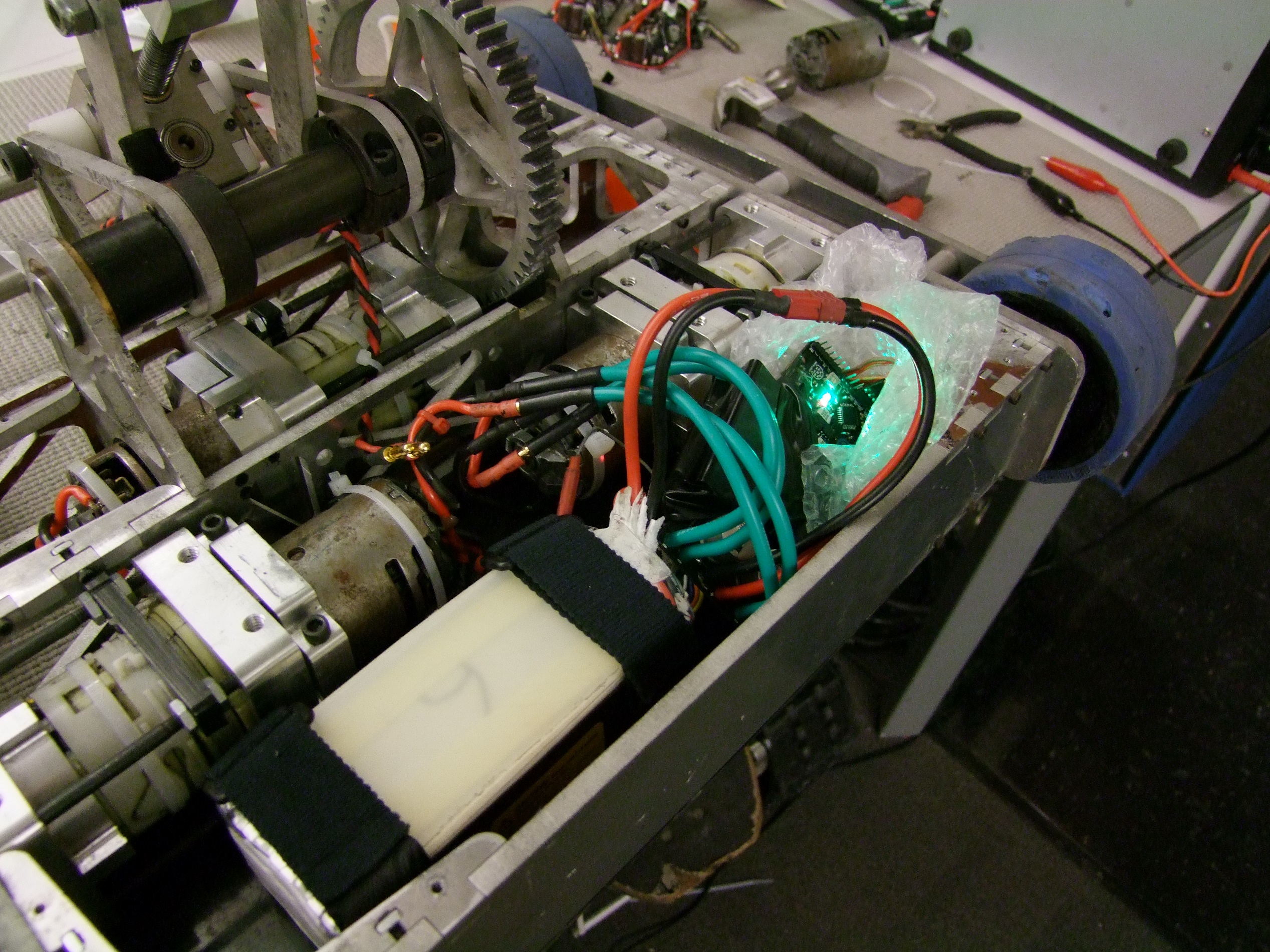
Two test units of Revision 3 built out and ready for abuse. At this point in development, the firmware was left in an R/C-only, hacked together mode. I began refactoring code I’d written “just to get by” for Motorama. At the same time, I started testing the boards using some standby motors:

Here’s Rage2 being tested on some motors it’s meant to drive – something roughly DeWalt sized, perhaps, and a scooter motor. I’m finding out some critical characteristics of the system, such as “Will my MOSFETS consume themselves?” (the answer is some times), and “Will it reset or stumble because of noise?”

Unfortunately, the answer to the last one is yes, and probably contributed to the Revision 1 unit that died at Motorama. With any hard reversing or command stepping – moments when the current draw increases sharply – the controller would reset, brown out, or exhibit other forms of bad behavior.

Uh oh. I’d been through this before, with RageBridge The Original, so I immediately checked the usual suspects. Poor ground routing. Placing capacitors in the wrong place such that they broke the grounding discipline. High power switching next to vulnerable signal traces, and so on. In the world of power electronics, where you put things is often more important than what you put there.

That’s my 5V logic power line, measured at the output of the power converter, being punched by nearly 1Vpp transients.

The brown wires are scoping points where I’d pay attention to the behavior of the system. The two blue wires were intended to jump the logic power input – which, up until this point, had been taken from the very end of the power plane feeding four gigantic MOSFETs – and gives it its own connection directly at the bus capacitors. It’s kind of like making a reverse Kelvin connection for the logic power.

As I suspected, I made a “cap derp”. The Allegro A3941 datasheet is not very clear (to me) about what it considered signal ground or power ground. In my view, it could stand to be a lot more descriptive about which pins need to be considered “dirty” – directly connected to switching power, so they should under no circumstances be routed to logic/analog ground. Instead, they choose to distinguish between “quiet ground” – what I’d call the logic ground – and “controller ground” vs. “power ground”.

I think I made a mistake here in routing the chip’s main bypass power – which is connected to VDD (battery positive) and “controller ground” – which I interpreted as logic ground for this board, but really should not be. I decided to try jumping this capacitor directly to the chip’s “ground” pin instead of taking it through the ground plane. I did the same for several other capacitors indicated on page 18 of the datasheet, forcing their “ground” sides to avoid the logic ground plane and basically making the only access point of the chip to the logic ground plane at its own ground pin (instead of in a few places).

These two hacks together basically resolved the resetting problem. I could no longer get the DeWalt – a very “dirty” motor, electrically speaking, to reset the board even with current limits off.

Once again – not what you put on the board, but where you put it.

With that cluster of issues resolved, I pushed a “revision 4” with a few other changes like trace optimizations under the microcontroller, separating everything into a “tree” topology as much as I could – no longer was the 5V supply for the chip coming from 2 different places (!). All the microcontroller’s grounds were gathered and tethered to the plane at 1 location. I also separated the 5V line into a “clean” and “dirty” line – the dirty one is the one fed out to the headers, leaving the “clean” line, which is tapped after the final LC filter stage, to only the microcontroller and current sensors.

Some illustrations of trace optimization for the microcontroller region.

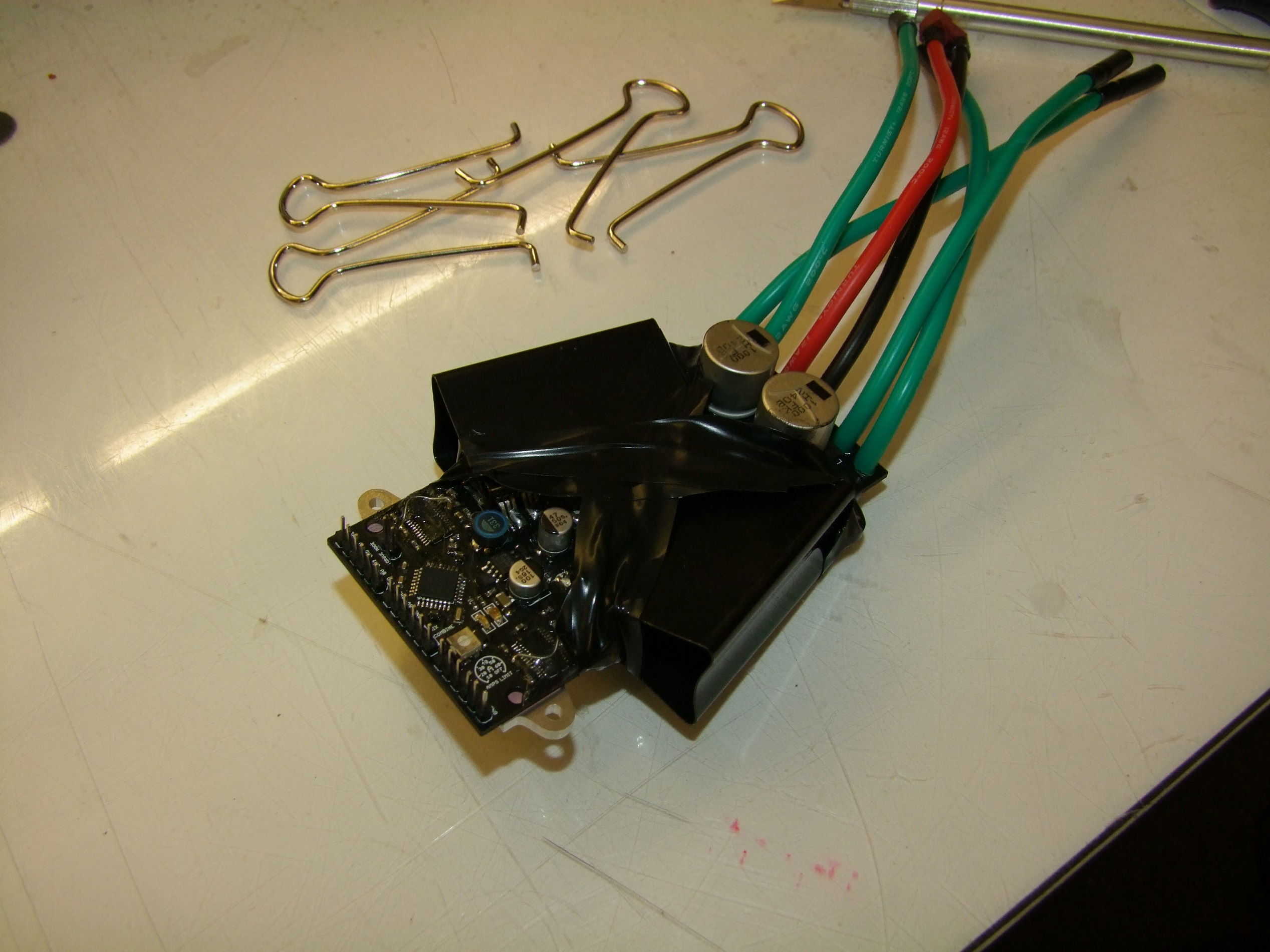
A week and some later, Revision 4 appears…

Okay, so I still had to put them together. This is what the board looks like.

Yes, on the last revision, I forgot to hit “Black LPI please!” and so it was green. I shall not make that mistake again.

This board refused to power on at all. No matter what, the 5V rail never came on, and instead hovered around a few tens of millivolts. What gives? How did I take that many steps back!?

I have a tendency to resort to “explosion debuggin” quickly. That means just running unlimited amps at a low voltage through what is shorted, and seeing what begins smoking first. Every motor controller I’ve made save for LOLrioKart’s controller has been “explosion debugged” at least once. And that’s only because I was running low on the large “brick” MOSFETs.

I took one of the spare boards and ran 10 amps through the 5V rail. Amazingly enough, nothing started smoking, indicating something very low impedance and near to the source. The board did get suspiciously warm in one corner, so it was under the microscope…

Oh my goodness.

It’s a left over stub of a trace that I thought I had erased, but in fact was still there, bridging my 5V straight to ground.

So you might be thinking… But Charles, wouldn’t DRC have caught this? Well yes, but my boards generate so many DRC errors (on the order of 1500+) I just ignore them all and use freedfm.com to check for the most obvious stupidity, but it doesn’t tell one net from another!

This is really just telling me I should set up design rules to actually conform to how I design boards ಠ________ಠ

Well, I suppose I’m glad I don’t have to do this for 250 boards.

A revision 4 board being absolutely hammered to death by the “end boss” of motors – the AM Equipment “D-pack” motor, a marine diesel engine starter motor that, many years ago, drove heavy- and superheavyweight Battlebots with contactor control because no ESCs existed which were hardcore enough to handle them. They can easily draw over 1,000 amps at 12 volts, and their no-load current alone is 30 to 40 amps.

And RageBridge passed the test spectacularly. Check out the “abuse video” here, featuring some other motors while I’m at it.

This is not to imply Rage can control 1,000 amp motors, but that the current limiting algorithm is robust. If I held onto the throttle for longer, the FETs would have unsoldered themselves and attempted to escape. It’s ultimately still thermally limited.

Some more brown fungus sprouts to double check that the noise demon has been exorcised enough within the performance envelope of the controller to not be a nuisance. Notice how I didn’t say eliminated. There’s no such thing in motor controller design.

The story, however, doesn’t end there. You know this to be true because if it did, I would be taking orders right now.

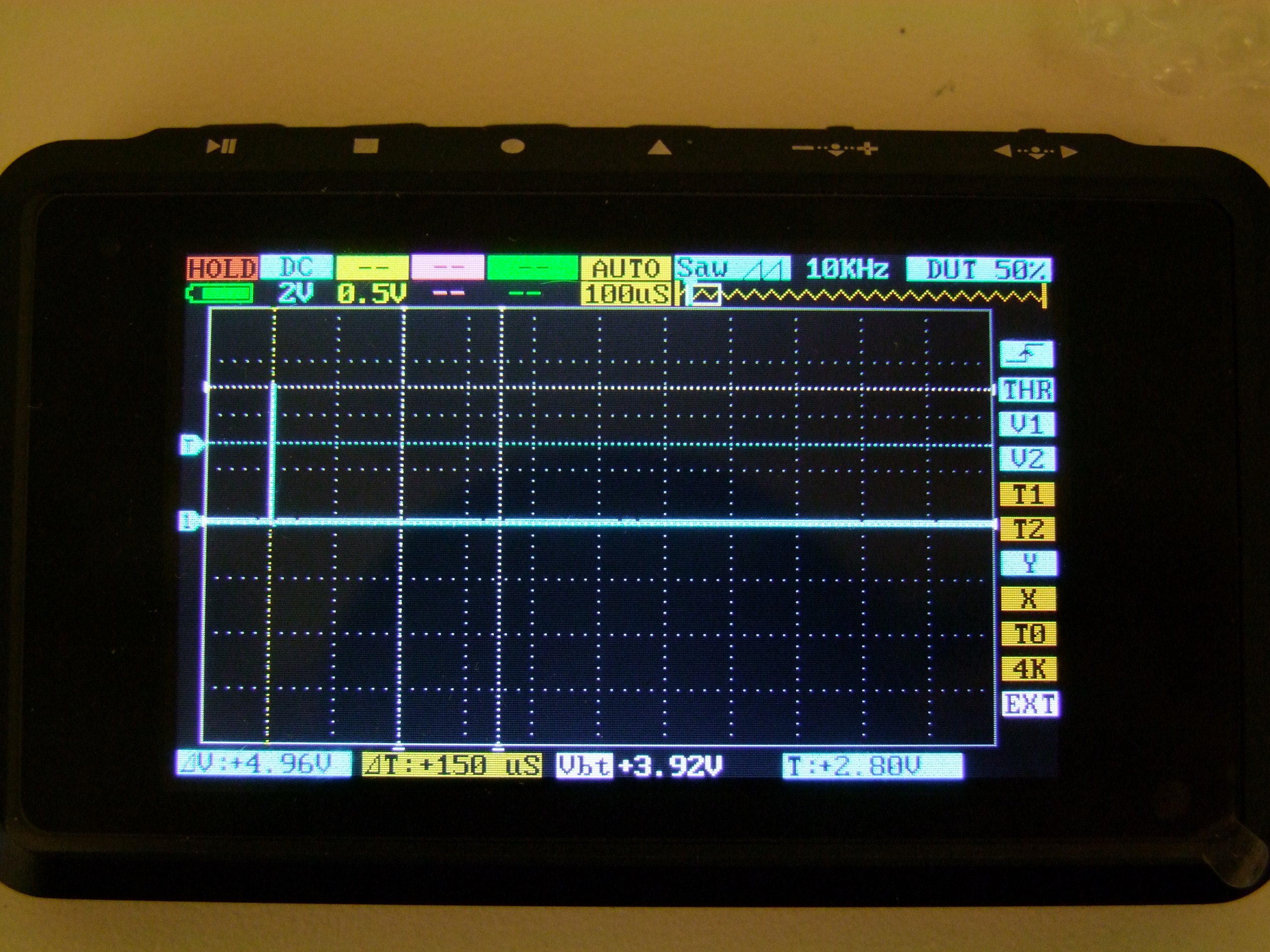
Ever since one of the late models of RageBridge 1 prototype, it has not wanted to operate above about 33 volts. The 5V converter would just shut off and enter what seemed to be a discontinuous mode, or some other mode where the frequency of switching was cut back drastically. Here’s an example, looking at the output pin of the converter BEFORE the inductor:

That’s normal – 24 volts in, 5 volts out. As soon as the voltage crests about 31-32 volts, this happens:

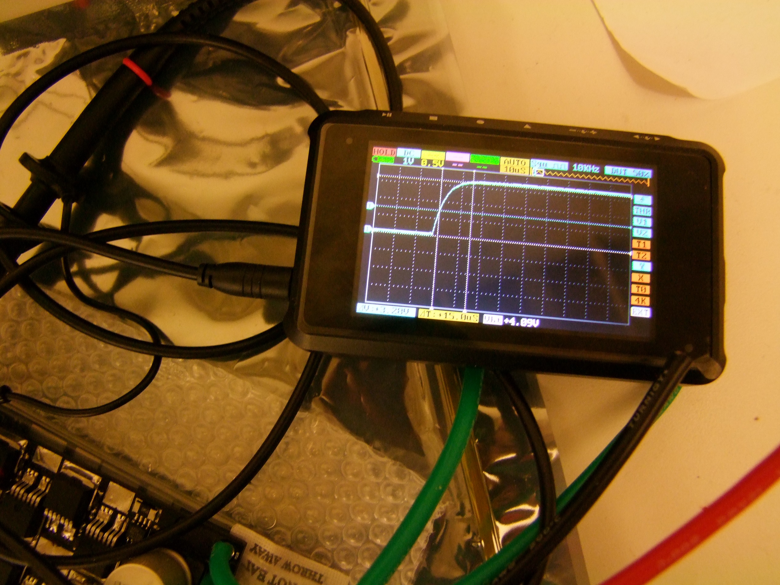
Less than 1 volt out! The ringing indicates that the buck converter is operating in discontinuous mode, but to enter it so quickly and suddenly? Something was going on. During this time, the LM2594 chip itself also got hot quickly, which is not advertised or documented behavior in discontinuous mode.

This fact has prevented RageBridge from operating above 30V reliably, forcing me to rescind the “up to 36V nominal” specification, which fortunately only affected a very small number of users.

So what gives? The LM2594HVM chip is supposed to run up to 60 volts. All my parts in that part of the circuit are 50V on the input, so it ought to at least be fine with that.

I ended up spending the night trying all sorts of stupid things, like making these inductor sculptures. Perhaps the inductance was still a little on the low side? After all, my HV requirements are still in the “coffin corner” of the LM2594 inductor selecton chart.

Nothing changed.

So what has been a constant factor in these boards? The LM2594 power converter design, which has been more or less copy and pasted from older schematics without change. However, everyone else seems to use them fine, including Shane. Since we talk about motor controllers like normal 20-something cosmopolitan guys talk about craft beers and beard maintenance (I have nothing in that department), I went to him for some more perspective.

Umm… let’s take a look at the schematic.

That part number – the MBR120VLSFT3G, is a 20V, 1A Schottky diode. In fact, I found the exact version of RageBridge 1 where I elected to put this diode in: it was when I switched back from the LT3433 buck-boost converter and remade the LM2594 circuit from scratch.

This sounds all too familiar.

Anyways, I likely picked that diode to minimize the losses associated with forward voltage, forgetting the fact that the Output pin of the LM2594 is connected to battery voltage periodically. The lesson here is therefore

don’t use 20v diode at 30v it doesn’t work

I shipped 94 of these.

Sounds good. I replaced both of the MBR120VLSFT3G parts with 50v parts – what I used in RageBridge versions long ago, the STP0560Z.


Three of the four Revision 4 boards in various stages of construction here.

Undergoing a little more stress testing here, now with the D-pack hooked up to a…. leftover propeller from the GLP electric boat class. I wanted a bit more viscous load such that it can draw more amps at higher duty cycles, as well as have a up to 950% greater chance of decapitation.

What else is new? After validating R/C mode, I used the same output driving kernel to make the “EV mode” a lot of you have been craving. I made the signal processing code as modular and functional block-like as possible, sacrificing some speed for the ability to pipe whatever garbage signal into it I please.

Analog mode has two submodes :

  • “unmixed”, using a sprung throttle. Single ended, expecting 1 – 4v active range to represent 0 – 100%, with a discrete reverse switch, or
  • “mixed” using 2 analog joystick axes centered at 2.5V, with a 0.1 to 4.9v active range, controlling forward and reverse and turning in one joystick. This was even easier to write, because that’s literally the same code as the R/C mixing mode.

Selecting the “Combine” jumper forces the outputs to act together, creating a single channel controller. Combine and Mix jumpers are mutually exclusive and logic-checked, since it can’t be single and 2 channel at the same time!

This single channel mode is still not entirely reliable. I’ve rebuilt one of the revision 4 boards twice, finally electing to scrap it.

Since it still is paralleling devices at the driver level, if one driver hiccups or lags, it’s easy to cause cross-conduction (a high side and low side FET of the same half-bridge turned on at once) and destroy everything instantly. To counteract this, I’ll likely increase the deadtime – which right now is just barely enough to not cause cross-conduction in one channel mode – to permit more timing slop.

Will from Hypershock paid a visit to help me test single-channel R/C mode on Hypershock itself. Unfortunately, the aforementioned unreliability made this test largely a flop. However, if I improve this reliability, Rage2 in single-channel mode is a great match to a single “short” Ampflow motor, which means it’s not out of the question for use in heavyweight / BattleBots classes.

The price of progress – the twice-rebuilt and scrapped board, along with some more destroyed parts. After a board blows up once, none of the semiconductors are really the same ever again, so I’m not sure why I even bothered with rebuilding.

When one Rage dies, 10 more take its place!

These are “revision 5” boards – hopefully the last of the revisions, and once assembled, will go out for beta testing. A few are slated for appearance at Dragon Con in 2 weeks, another few are being sent to Power Racing Series competitors to see how it holds up under the rigor of racing. Two completely different loading regimes and set of input & output requirements!

It’s time to order more gate drivers.

Also, here is an interesting picture.

Motorama 2015, Part I: RageBridge v2 Drama

Let it be known! I shall not update my blog with the Motorama event report until all other MIT-based Motorama competitors update theirs. If you see the Part II, it means I’ve finally been satisfied… or got sick of waiting. I am a man of unyielding principle. For some background on this, through a spectrum of high-pressure sales tactics and peer pressure, an astounding number of new builders are attending; by my estimates, we had 6 totally new entries (and attendant totally new builders). One group elected to complete in the Antweight (1lb) tournament that runs on Friday, something that even I don’t normally do!

As I mentioned last time, none of the bots were in bad shape pre-Motorama, but I’ve been expending immense energy trying to get RageBridge v2 working in time. So why not start with it?

RageBridge v2

Previously in the adventures of RageBridge, I had gotten the bulk of the automatic input-reading organized through a depth of register-diddling greater than what I’ve ever dared do before. If you know me and how I program embedded systems, you know that registers are my most favorite things about the process, and there’s nothing I look forward to more when starting a new microcontroller project than hunting through the thousand-page programming manual and trying to write bit manipulation expressions.

Now, with the retching out of the way, time to try writing an input-taking routine.

One programming challenge for RageBridge v2 was the automatic input-mode detection. I don’t have a rail of jumpers to select the operating mode, and don’t intend on having one since the board is already SLAM-PACKED WITH RAGE!If I can get a reliable automatic input detection, then great! If not, then different firmwares will be made available.

The inputs to decide between are R/C, Serial packets, and analog. On power-up, Rage will take a second to let the inputs stabilize and any partner electronics like receivers and master microcontrollers boot up. Then it will, ever second, check for…

  • Serial buffer byte presence. It will read the first few bytes of the serial buffer and check for 64 or 192 (out of 255, an 8-bit value). These are “idle” commands for left and right motors. This convention is common to several robot controllers that have “simple serial” protocols, where 1 – 127 controls one motor and 128-255 controls the other. If these bytes are present, then assume Serial operation.
  • If there are no valid serial bytes, it will set up the channels 1 and 2 input pins for analog voltage reading. Additionally, it checks if the MIX jumper is set. MIX assumes “joystick mode” where the sticks are centered at 2.5v, so both inputs have to be at this level (within a small deadband) to select that mode. Else, if MIX is not in, it assumes 0-5v with 1-4v as the active range, meaning the signal must be approximately 1V (within a small deadband) to select.
  • If the analog voltages aren’t within the correct band (or it’s pegged to 5v due to the internal pullups) it will initialize the R/C inputs and wait to collect input pulses. Once valid input pulses for both Channels 1 and 2 are received – which must be 1500us +/- a deadband – then the mode is selected. The forced neutral-only mode selection acts as a zero-power-on-startup check too.

This pattern repeats once per second, and the motors will not drive until the appropriate signals are received. Overall, the code looks something like…

I had thought the Analog part would be the most difficult, with the deadband requirement and all. But in fact it was quite easy. With a few test potentiometers and scooter throttle handles, I could get it to reliably pop into Mix or non-mix mode every time. R/C mode proved to be the issue – no matter how much delaying or waiting I had it do, across different receivers even, I couldn’t get R/C mode to work!

As a bit of background, I use the PinchangeInt library to capture R/C pulsewidth signals without having to use the blocking (prevents rest of program from doing anything) pulseIn() function in Arduiono. After writing up a quick R/C only input-taking test program, I noticed something peculiar. All of the inputs read, no matter one channel or the other, simply looked like they were overflowing the variable over and over:

The PinChangeInt interrupt service function takes the difference between the micros() calls of two functions, a rising edge and a falling edge, to get the delta-time. micros() is an unsigned long (32 bit) type, and my R/C pulsewidth variables are signed integers (to be used later in mapping/scaling math). The pattern of values said to me that something was just counting further and further up – not taking the difference at all.

Checking with an oscilloscope confirmed that only one interrupt was being serviced:

I set and cleared a pin on the chip whenever the rising edge or the falling edge interrupt was being triggered. As expected, only one edge appeared. With this test, however, I couldn’t tell if it was the rising or falling edge…

…especially when it seemed that SOME TIMES, both interrupts were working! This shot clearly showed a 1000us pulse width, with two triggers. So what the hell was going on?

By the way, this is the first official usage of the DSO Nano 4 channel digital scope I picked up in Shenzhen! All of the initial debugging shenanigans happened at my desk as a result.

I reached out to the Arduino Forum, where the developer of PinChangeInt had a thread about the library, and learned some interesting facts… namely, that the code should never have worked the way I wrote it in RageBridge 1, and a couple of projects before that.

Well, hmmm.

To clarify without having to read the thread, here’s the difference. I’ve written all my R/C input code in the form of two separate interrupts, RISING and FALLING edge, since 2011 when I first started using the library. The form is similar to this, which was an excerpt from TinyCopter:

The takeaway is that there are two interrupts per pin. Allegedly, this should never have worked!

Yet, compiled in the latest version of Arduino, with the latest version of PinChangeInt, this is what happened. The same kind of nonsense I saw in my initial testing. It seemed to me that only the interrupt I defined last was executing, which contradicted what I saw on the oscilloscope – that some times both interrupt service routines did execute. But I freely admit that this could have been a oscilloscope artifact.

Pictured above is the structure that SHOULD HAVE been used this whole time – a single interrupt service routine, executed whenever the pin CHANGE’d states, and which subsequently read the state of the pin:

As the collected 1500us (approximate) pulsewidth shows, this works fine.

So what gives? Not even the developer knows, apparently! My “two interrupt” form was never supposed to work. I can only assume that between Arduino version 1.0.1 from 2013 andthe current 1.6, and from the first version of the PinChangeInt library I used to the current, that enough changed such that whatever loophole I used was no longer possible.

Either way, with the solution found, I backtracked a little and modified my “two interrupt” program to show which interrupt “won”, so to speak.

I changed the two-interrupt type to only increment or decrement a variable depending on which component was called. As I suspected, the last ISR to be declared always “won”. Here, vol_ch1_pw is being sampled by the main program loop, which shows it always decreasing. if I swapped the declaration order, it would keep increasing.

Whatever. Chalk it up to falling victim to the stochastic nature of Arduino developers, and y’all can lecture me about this is why you always use the programming manual yadda yadda I-don’t-care. It works now:

The PINC & [byte gibberish] portions of each ISR simply “select” the pin to read. Notice how it starts at 0b00000100 – this is because the first two bits represent the first two pins of port C, PC0 and PC1, which are reserved for the current sensors. PC2, PC3, and PC4 are the three channels of input.

With that mystery resolved, the entire automatic mode detection code worked instantly:

Shown above is Analog (unmixed, with a scooter throttle) and R/C mode inputs. Serial inputs are hard to capture on video since it’s one microcontroller talking to another. I assigned different blink patterns for the different modes to help during debugging, but they will be retained for actual operation.

The blink routine itself is interesting by itself. It’s the first time I’ve used an otherwise unused hardware timer (Timer 2 in this case) exclusively as a blinking machine. Here’s the code snippet that makes it work:

The software “prescaler” portion was carried over from my previous different motors controllers’ code, where it was part of the main loop. Either way, something executes that if() and builds up the prescaler variable. After enough times of this happening, it executes the blink part of the code.  Timer 2 was set up during the initialization as a simple counter with a hardware prescaler of 64 from the system clock of 16MHz. This resulted in a counting speed of 250KHz – every 4 microseconds, the count would increment. Left to its own devices, this count would overflow after 256 counts, or 1.024 microseconds. To obtain a clean (to us humans) number, we start the count at 6 (BLINK_INITIAL_VALUE) such that it only has to count 250 times per overflow, giving a clean 1 millisecond timer. With some frills, that’s basically the millis() function re-implemented. I could have included this in the main loop as a call to millis() and it probably would have worked just fine, but I wanted it on a separate interrupt to not hog main program loop time.

Next up is that horrific line of bit manipulation that somehow worked the first time. What this line does is turn PB5 – a.k.a Arduino pin 13, the LED, on and off according to the state of a byte that is being used purely as an 8-bit array, where a 1 means “LED on” and 0 means off. current_blink_pattern is this byte, and it’s assigned whenever the mode changes so the blinking pattern changes.

The line first takes PORTB (the output status of the pins) and masks off PB5. Next, it grabs a copy of current_blink_pattern and shifts it right by some number of bits – basically an array counter that is reset at the bottom every time it exceeds 7. It logical ANDs this with 0x01 to isolate the least sigificant bit (rightmost bit). Finally, it moves this bit leftwards 5 positions to line up with PB5, and jams the two together.

The result is that PB5 is always turned off every cycle but the result of (current_blink_pattern >> blink_index) & 0x01 turns it back on (or leaves it off for this cycle).

With BLINK_INTERVAL set to 100 and the interrupt happening every 1 ms, the result is a 0.1 second blink duration where the LED can on or off. Now, strictly speaking, with 8 bits I can only make 0.8 second-long blink patterns. That’s fine, I don’t care.

Yes, I get all the way to the end of this timing problem and don’t even care that I get clean 1-second long patterns.

One thing that all the scoping to get to the bottom of the interrupt issue was discovering that the input filter capacitance I put on the input pins, which are shared by both analog and digital signalling, was too great.

Ouch, that’s a 10us rise time there. The fall time is about twice as fast, but still bad. I put 4.7nf input caps on the pins, which I guess is too much for another little microcontroller’s pins to drive. I might have to compromise analog signal stability (or implement software filtering at some point) in favor of making the edges sharper.

Once the bizarre library behavior was accounted for, and the automagic mode selector finished, the rest of the code was actually quite easy. In concept, it was just like RageBridge 1, but better implemented.

First, the inputs are sampled and cleaned, with erroneous signals replaced with the “last known good” one and a signal-bad flag set. Next the signal is mapped to an output variable. The output variable is bounded by a maximum increment per loop (ramped), and the result deciphered into PWM + direction and output to the drivers.

Whereas in RageBridge 1 all of this took place messily within 1 loop, I organized it all into procedures so the different modes can be better isolated, even thought hey still acted on global variables:

Of course, right now, I only have the R/C code written.

I did away with the incredible machine that was the mapWithRampingAndDeadband() function of RB1. That was basically broken up to its constituents – the deadband was taken in the input processing stage, and the ramping output mapping just a compare and += or -=.

Soon, it was time to test. Without having made compatible heat sinks yet, I, uhh, created an innovative board clamping system to secure it to the old style Ragebridge 1 heat sinks.

Innovative. That’s the word.

It’s totally not “two binder clips and some electrical tape”.

The test subject was Clocker. By this point, it was Wednesday afternoon, so this was going to be a determinator as to whether or not I try running the new boards at Motorama or not.

During a few on-the-bench tests of pegging the throttle back and forth, I was able to get the board to reset several times. This is not a good sign, as it shows the design has noise coupling into it in some place that is making it all the way to the logic. I have a few suspects, namely the long analog power and ground traces feeding the current sensors and the less than optimal placement of the logic power supply taps from the main board power planes.

My first battle tactic is always to insert capacitance where it doesn’t belong to see where the noise was coming from. For starters, all the 0.1uF logic circuit buffering capacitors were changed to 1uf. Now, strictly speaking, I suppose it was capacitance that was there in RageBridge v1 but was removed, since all of those on version 1 were 1uf to begin with. I also changed the primary input bypass capacitor (on the Vcc pins of the micro) from 1uFto a 10uF.

For the most part, as far as I could tell, this resolved the issue. But capacitors are band-aids to the real problem, which is layout. I’m going to have to take a closer look at how the logic power is feeding in and out of the big patches of battery voltage and ground planes, all being switched hard tens of thousands of times a second.

There was also one particular pin connection on the A3941 gate drivers which I was unclear about, which may also contribute to noise coupling via ground fluctuation, but I will address that once I put together some more boards. In the mean time, I taped the board back into Clocker for some hard driving.

For the most part, the test went quite well…

This test revealed a very important hidden flaw in the drivetrain that I’m glad was caught. Namely, when I last took apart the DeWuts on Clocker to change the motors, I neglected to recheck the torque-limiting clutch screws. The clicking, clutch-slipping noise in the video is exactly that. A little bit of hex key wiggling – no sprocket removal even needed – and things were tightened up again.

During this and subsequent bench tests, I couldn’t get it to lock up or reset no matter how much I gunned the motors around. In fact, I did it so hard that…

What you see is a thin pall of DeWalt smoke from some rapid input reversal testing gone wrong. It seems that one of the motors had a borderline commutator short, which quickly became non borderline when rapidly smashed with +/- 26 volts.

The resulting quick short also took out one gate drive chip and two FETs on the half of the controller driving that motor. I replaced them both in 5 minutes, along with sending this motor to the pile of sad motors.

I ended up deciding not to run RageBridge v2 (board revision 1) in Clocker for this event, since I didn’t want to have to do ESC debugging in the field while my match is 2 minutes away. What I did do in the remaining day was add in the much-requested combine mode, which hard-parallels the two channels together at the hardware level. This enables Rage to function as a single large 1 channel ESC.

That part was easy. In combine mode, only channel #1’s current sensor is read and the assumed current is just twice that. The current control loop output calculated for channel 1 is applied directly to channel 2, making the assumption that the two halves, driven off the same PWM timer with the same gate driver, will switch on (within a small fraction of the total switching time) with eachother. This is not the most robust method, as it totally slaves channel 2 to channel 1’s mercy, and a failure on channel B will probably cause the whole thing to grenade. Maybe it’ll get revisited shortly.

Why did I put Combine mode together? Because another bot this time needed it…. and for that, we’ll need to wait for Part 2.