It moves. Finally, after k months, l complete redesigns, $m invested, and n setbacks, I have a working model of the in-wheel motor for Snuffles Reloaded. With the MIT Mystery Hunt now in full swing, I haven’t been logging the last few build hours over the past few days, so now it’s time to catch up.
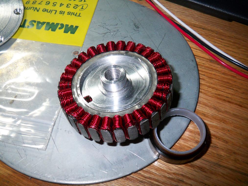
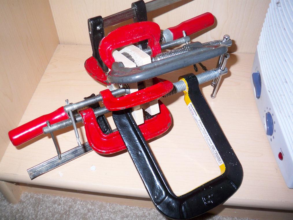 The stator got a bit mangled as I tried to wrestle it onto its mount. No worries, a few dabs of epoxy here and there to secure the plates and a cuddling session with all 8 of my various off-duty clamps fixed that quickly. The heater it’s next to helps the epoxy set quicker and stronger.
 Everything looks hardcore with a few flathead cap screws on it. For some reason, three of four area hardware stores did not have the cap screws I needed. The fourth had exactly 16. The motor needs exactly 16 screws.
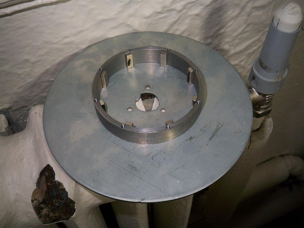 Back at MIT, starting work on the magnet ring. There are 40 magnets and 8 mounting holes, so five magnets are spaced equally in the arc segment between two mounting holes. I placed these eight “keystone magnets” first and set them on top of the radiator to bake the epoxy for a while.
I also keep food warm on this same radiator, and if I need a quick chilled drink, I stick it outside the window.
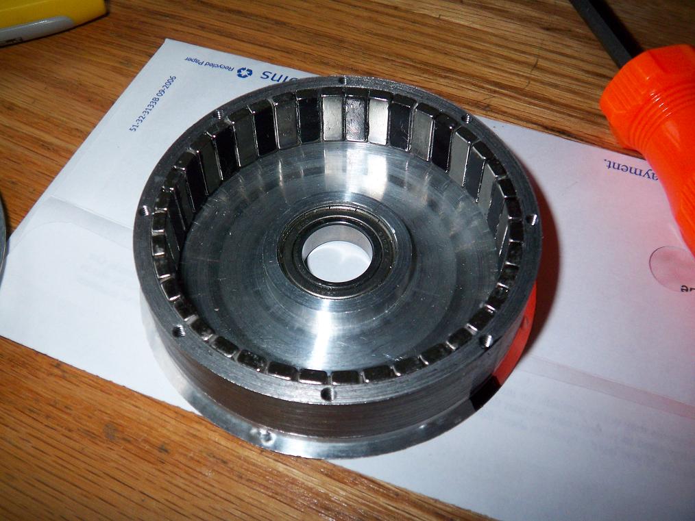 Magring completed and epoxied. Index card stock folded twice over worked perfectly as a magnet spacer, so there are no odd gaps or areas where two magnets are unequally spaced. Constructing this was the messiest thing I had ever done – I think I absorbed more epoxy working on this than I have in all my life so far. Also, the stuff started to gunk up after 10 minutes or so (protip: if building motors, use some good quality 24hr epoxy). The magnets loved to leap off whatever I’m using to hold onto them and make a mess as they splat into the steel can. Adjacent magnets also like to stick to eachother, and the whole can would consume whatever tool I accidentally waved over it in the process.
If life were Autodesk Inventor, I could suppress the Magnetism attribute of the magnets as I mount them.
 To the Media Lab shop! For some reason, I keep forgetting to bring my camera-camera to the ML and other off-dorm construction sites, and have to rely on the cell phone’s camera. Here’s some final machining prep to mount the motor to the scooter. The motor shaft center hole was threaded, the original wheel bolt holes on the Razor were drilled out (along with the wheelie bar), and the stator had its high spots and epoxy-gunked areas sanded flat.
At 4AM in the morning, the entire Media Lab building is empty. I was probably close to being the only person in the whole place, and couldn’t help but look over my shoulder and listen to every sound that did not originate from me.
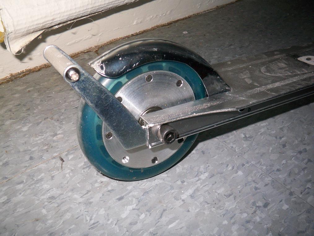 Motor without windings test-fitted on the chassis. It’s almost there! It’s just missing wires! And a center hole in one of the cap screws. For this task, I went to MITERS and chucked a cap screw up in the lathe.
These cap screws are made of some serious, serious steel. I blew through two 1/4″ drill bits before damning it all and popping a 1/4″ endmill into the lathe tailstock chuck. Surprisingly, it devoured the steel capscrew very quickly. This leads me to conclude that endmills rock.
When freewheeling around, the cogging of the iron core upon the magnets creates a resonance in the tube chassis at a certain speed. It’s incredibly annoying at this speed – a rather high pitched siren noise. Although typical of brushless hobby motors, the rectangular thin-wall aluminum tube that forms the Razor chassis amplified the noise a whole bunch of times.
 It had to go wrong somewhere, of course. I came too close to tempting the robot gods by being able to buy precisely the number of screws I needed. So of course when winding the first phase, I was off on the length of wire required by mere inches. So close, in fact, that I was only two loops away from being able to end that phase. If I had pulled the preceding coils tighter, I probably would have had enough!
This sucked. I had to cut off that coil, wind it individually, then join the two bits of magnet wire. Magnet wire does not solder well at all – I had to use a torch to burn the enamel off. Of course, the torch runs out of gas after one joint. I then had to resort to scraping the enamel off and waiting for the soldering iron to burn it off the rest of the way.
And then I couldn’t apply the heatshrink to insulate the joint because normally I use the torch at a distance for these things. It had to wait.
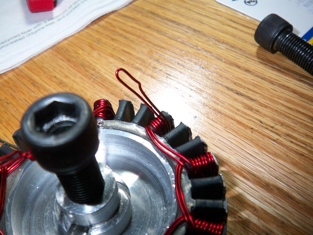
 In the end, all was well. This is actually the back side of the stator. It’s actually quite neat and orderly, like good shrubbery. Five and a half turns per pole (probably two few) of twin-strand 21 gauge wire for a rough equivalent of 18 gauge windings. Real 18 gauge wire was too inflexible for my non-rugged not-engineer hands, which were pretty much bloody stumps after pulling hard on 30 coils of wire ten times each (that’s 300 good tugs not counting repeats).
 Yeah. Here’s the other side. It’s a total clusterfuck since I couldn’t figure out how to overlap the coil transition windings and kept switching methods between coils. Surprisingly, everything rotates clear of the side plates. I’m very glad I left the extra .125″ of space on those.
But of course there has to be a catch to this somewhere. Yes, there is continuity to the chassis in the windings somewhere. The bane of hobby motor builders everything – improperly insulated stator combined with brittle magnet wire enamel make for shorts between phases. Again, if this were a real stator, it would have been dipped in an epoxy compound to remove all the sharp edges. Pop quiz’s motor is actually chassis-shorted also. I’m just going to run with this for now.
The proper thing to do is to strip the windings and start over, hopefully avoiding shorts. Fuck that, seriously. Fuck all of that. It looks shiny. Can’t you guys cut me some slack!?
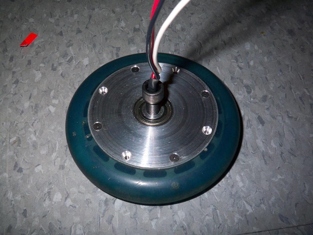 Closed up and tested for wire access. At this point, I was able to hook up a test rig and hold the motor using visegrips to spin it up. My large ESC was being nonresponsive, so naturally I used a small 25 amp controller I bought in China two years ago.
If you think Chinese parts suck nowadays, you probably thought they REALLY, REALLY sucked two years ago. You’d be correct. The controller was able to spin the motor up for about a second before something went poof.
I wasn’t sure of the amp draw since I didn’t have the RC meter hooked up, but it was surely not 25 amps. Then again, the motor was a bit rough to turn by hand, so that might have caused a current burst long enough to explode something. Oh well.
I later found out that the big ESC was nonresponsive because the receiver battery supplying +5v was dead. It doesn’t have a BEC.
 With the motor mounted in the scooter chassis and the wheel off the ground, it was time for a motor test!
The video of the first firing is here. MOV format, 3 megs. Yes, it’s rather rough and the controller burps a few times. With subsequent runs and some loading, it (oddly) smoothed out. I never knew you could break in a brushless motor.
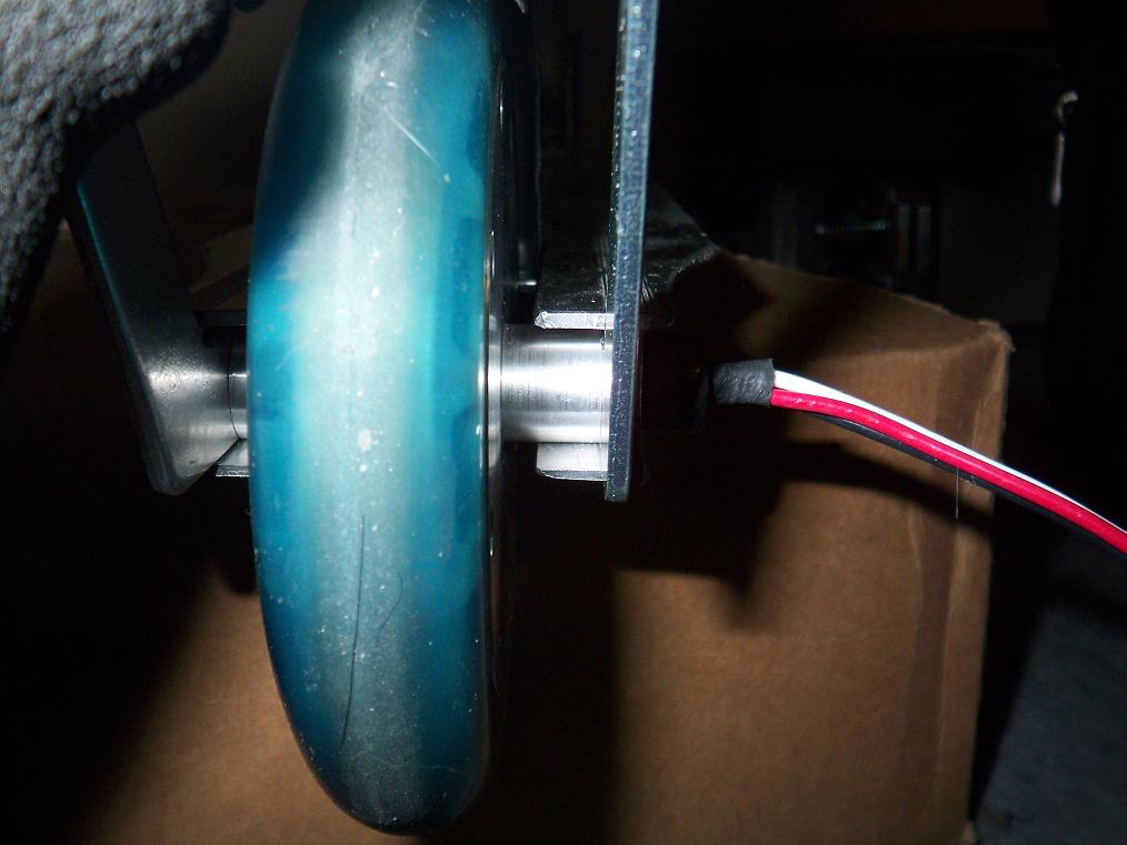 Getting the bundle of wires through the mounting holes at the same time as mounting the wheel was quite an adventure. I had to disassemble the wheelie bar, thread the bundle through, then through the chassis, then pop everything into place with a sharp whack. After that, the other side slides in normally. There is zero play in the whole assembly.
In the optimal design, the wheelie bar is replaced with a suspension assembly that makes the whole thing a module. No threading wires through too-tight spaces.
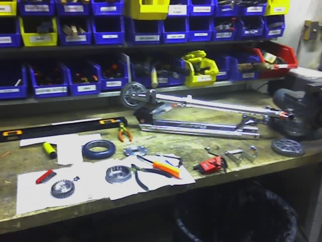
 Observe. This is the first duct tape test rig I have built for anything in almost a year (Snuffles 1 didn’t move until everything was mounted in its final position). The ESC, battery, power analyzer, receiver battery, and about 10 alligator clips were all bundled up near the back and strapped in place with duct tape. Surprisingl, it held together long enough for me to get in a few test runs down the hallway.
The result? Dismal, as expected. Acceleration was extremely sluggish and only noticeable near full throttle. Peak current draw was over 50 amps with steady current during acceleration of about 30-40. There were probably lots of bad contact areas and high resistance spots thrown into the mix.
At the end of a few heavily strained runs (the motor always sounded close to detonation) everything was surprisingly cool, The motor will probably get perimeter cooling holes drilled in the side plates anyway, since I want it to be (somewhat) continuous duty. It’s good to see the duct tape rig didn’t short directly against the frame and set the building on fire.
In the morning I’ll do a concrete-asphalt run to confirm its suckiness, since the hall carpet probably added alot of drag. It is also awkward trying to hold the big Spektrum transmitter in one hand, the handlebars in another, move the (non-sprung) throttle stick, and stand on one foot. At once.
Hopefully I’ll be able to video that run. In the mean time, IT EXISTS! IT’S LEGITIMATE! IT MOVES kinda AND CAN CARRY ME marginally AND ROCKS! It’s also a prototype, rather rough around the edges, and can stand alot of improvement.
Verdict: Needs more engineering before becoming viable.
Stay tuned for more! Meanwhile, bot on.


