Continuing the story of Ragebridge’s quest to find a stable power converter design, I received the updated version 3 boards earlier last week, and got around to assembling and testing them over the weekend. I think RB is ready, at this point, to enter the release candidate & fine tuning stage of the development process. But first, I had an adventurous time remembering what boost converters did.
First, if you want to skip straight to the RageBridge potential customer & user survey, feel free to just click through.
To summarize, the RB project has seen me move away from a known stable (but not that vintage) power supply design to exploring other ways of generating logic voltage and gate drive voltage in order to push the lowest operating voltage down below about 18 volts. My general setup has been dropping a switching regulator on the battery input and buck converting to 15 volts (gate drive voltage) and then a linear regulator to 5v (logic voltage).
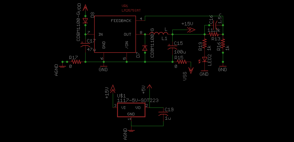
This arrangement has been reliable, but it pretty much limits the working voltage of the controller to greater than 13 volts or so. The switching regulator, a LM2594, can turn entirely on and pass the input voltage, but it has a 1.3 volt saturation voltage penalty. Add to that the other 1 volt or so of diodes (one before and one after), and the gate drive ICs turning off at 10 volts, means that operation down to that level or below is undefined.
My intention is to make this board also useful for 12v lead-acid and 3S lithium systems, of which there are still plenty, and hence I needed a way to make sure the board is logically determinate down to maybe 8 volts. The previous board version, as detailed in its post, explored an integrated buck-boost converter, the LT3433.
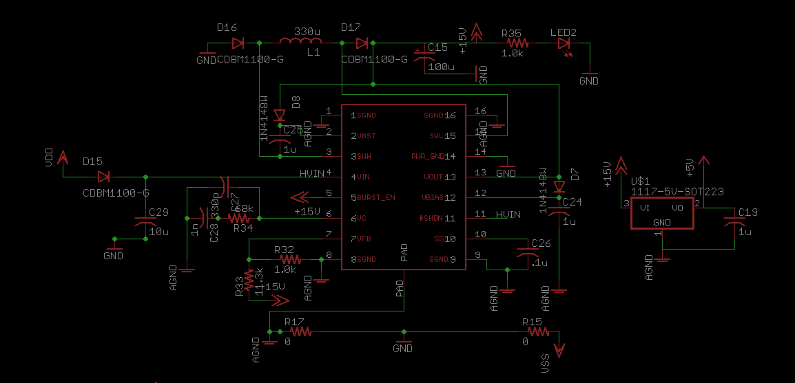
Unfortunately, while it could have worked in principle, it turned out the chip couldn’t supply enough current to run everything on the board. At around 20 volts, the output began sagging out of spec.
Turning my attention to a more serial arrangement of components, I decided to take the slightly less efficient (in principle) method of chaining a boost converter after a buck converter. In this case, I was going to convert battery voltage directly to 5v logic, and then from there, boost to 15v gate drive. This keeps the regulators (nominally) separate and out of eachothers’ affairs. The chip used was the LT3460, a small dedicated boost converter controller. There would be no more linear regulator, so I had to pile on the capacitors to keep ripple voltage lower and also added a transient voltage suppressor diode to the 5v bus.
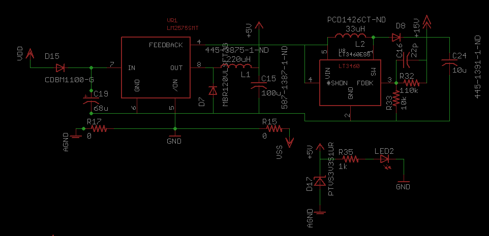
That’s where the design stood as of 3 weeks ago, and the corresponding board layout is:
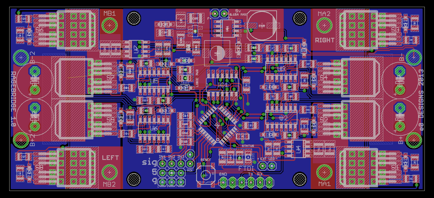
I pretty much followed the recommended layout of the 3460 exactly. This had better work. I sent out this design to MyroPCB, once again, but in 1oz only (since I was just out to test this converter, more or less) and…
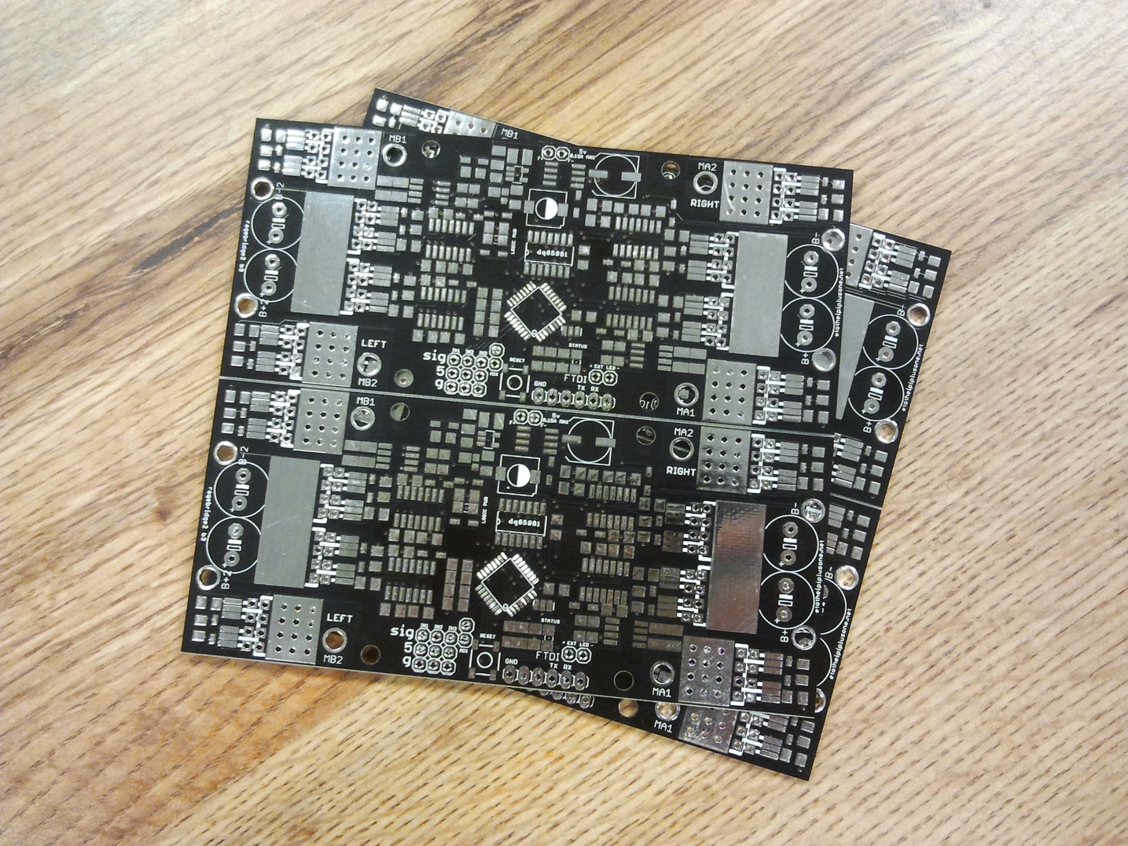
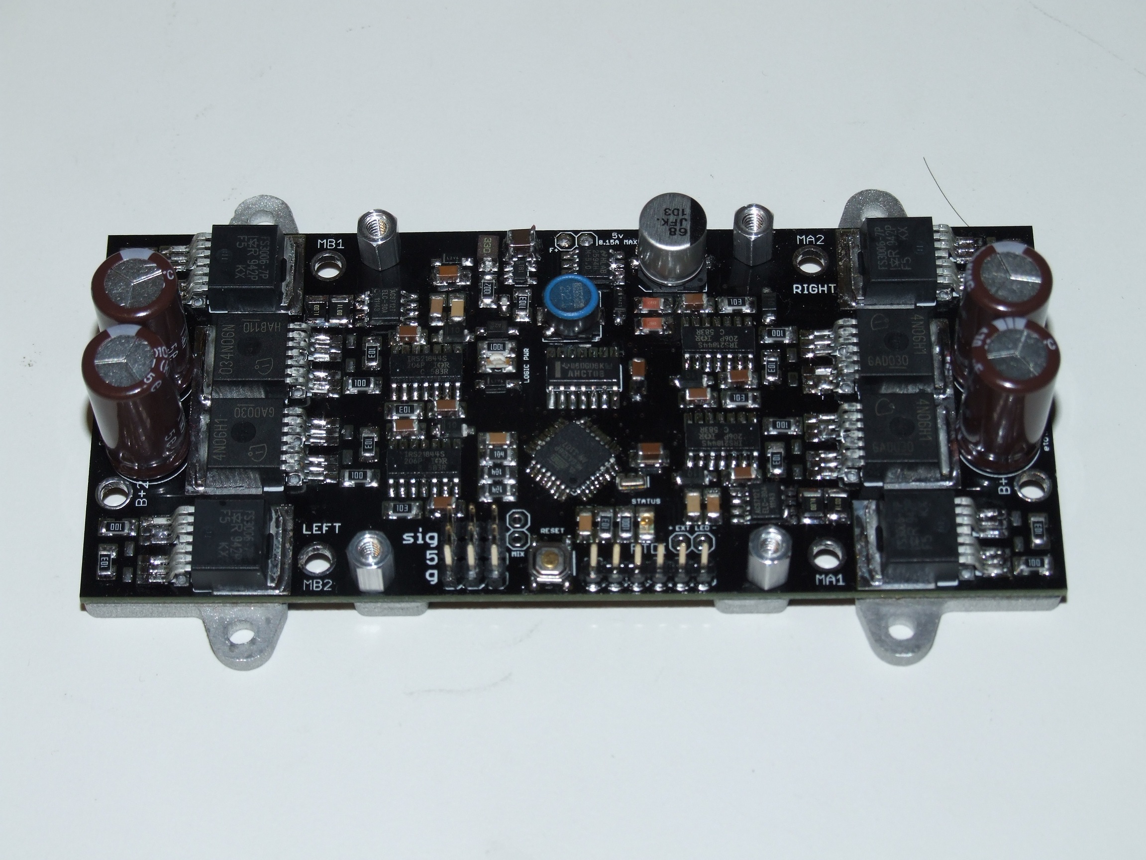
…in black. I’ve always wanted black boards – they just look so much more badass. As usual, I placed my Digikey order when Myro notified me of the boards shipping, but that seems to have gotten delayed, so my Digikey order appeared a few days before the boards.
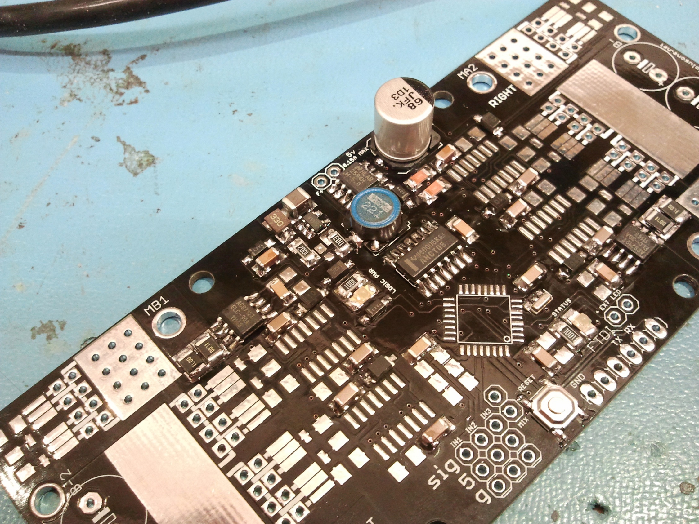
The first thing I wanted to test was the power converter, so it was assembled first thing. It’s important to note here that I also bought a same-footprint-and-pinout equivalent of the LT3460, the MIC2288. The alternate chip has a much higher (1.3A) switch current limit than the 3791 at 300mA. This will become important later.
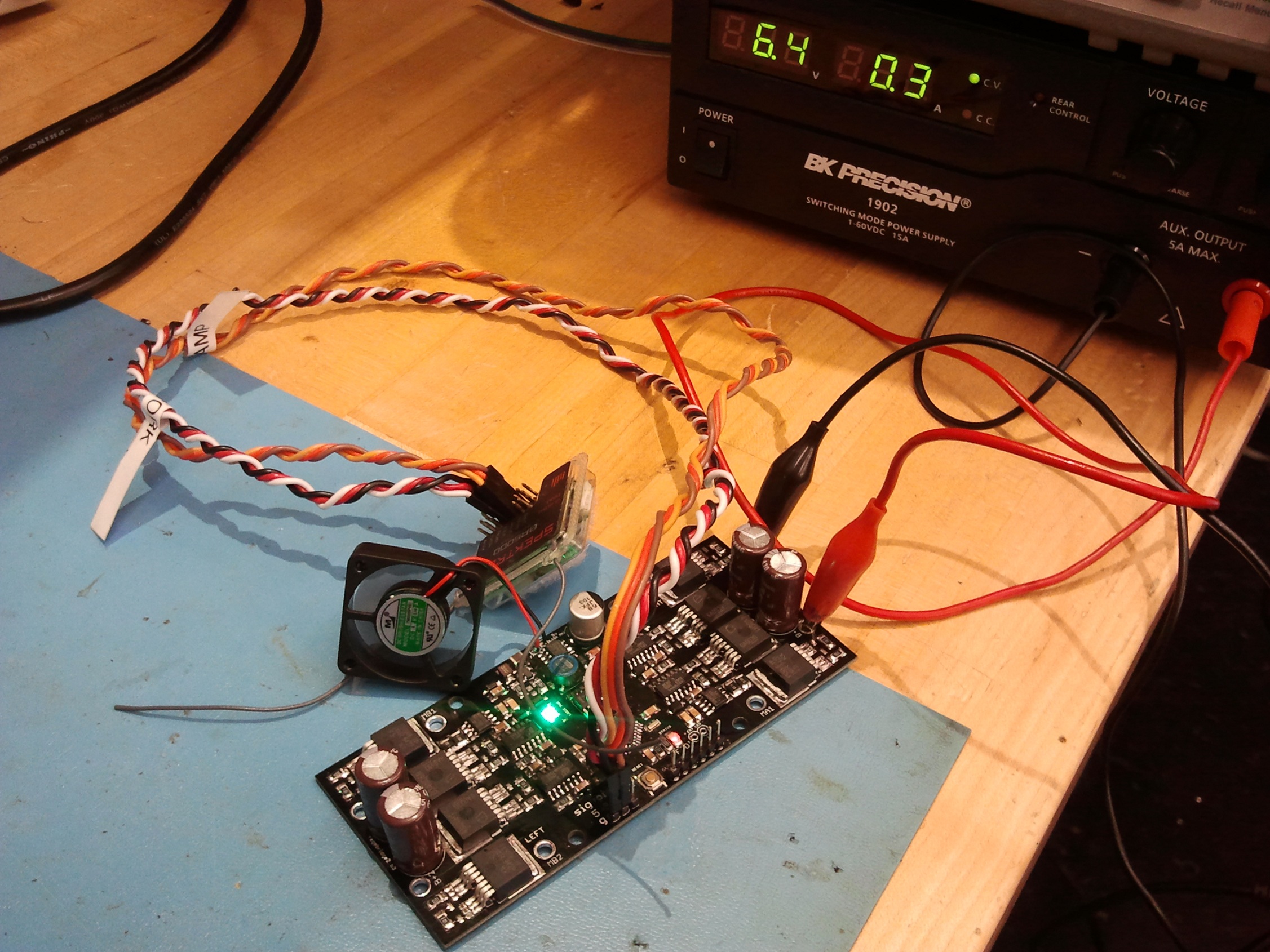
With the power converter testing out good, I finished one board fully and did a load test with a small 5v fan (0.15A) and a spektrum receiver (0.09 to 0.12A, because what?). This was just to make sure the thing could hold up under load. The gate drive, at this point, was not yet enabled (the receiver was in failsafe mode).
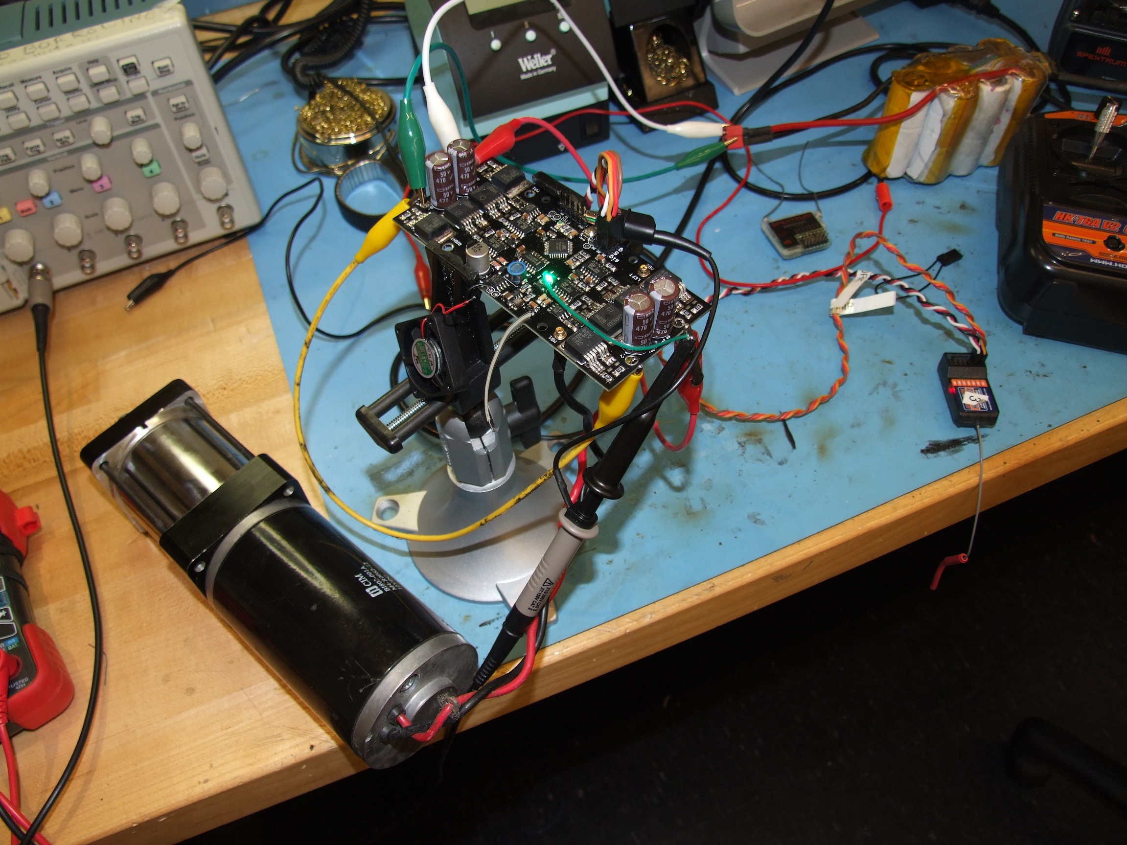
After that was done, it was time to drive motors. I remembered that I had Segfault’s old drive motors, which are CIM motors stirring a hydraulic brake a 27:1 Banebots P80 gearbox filled to the brim with thick grease. This thing draw like 15 amps just running freely, and an overvolted CIM can certainly push enough current to scare most controllers. One of Überclocker’s batteries provided the bus voltage. Even though testing unknown controllers on a battery (a source of potentially infinite amps) is a bad idea, I did it because..
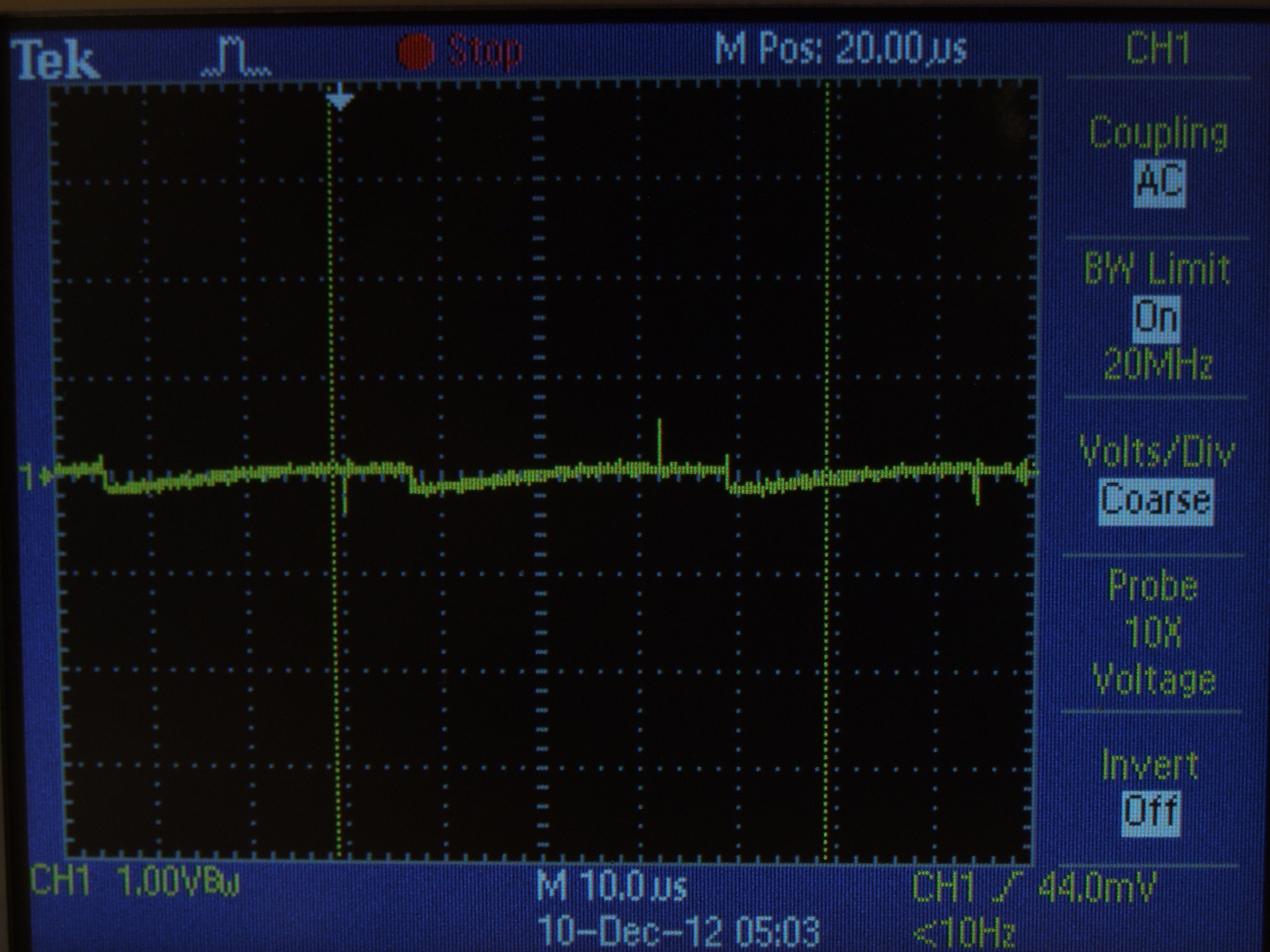
…ouch. The sketchy switching lab supply has that as its output voltage waveform. I thought I was chasing down a noise issue on the board when I realized anything the scope probe touched was displaying this waveform or some linearly transformed version of it! Oops. I had forgotten that switching power supplies are usually pretty bad in terms of voltage ripple and noise, cheap ones especially.
It might be worth iterating to other aspiring secret board ninjas that you DON’T EVER USE A SWITCHING POWER SUPPLY TO TEST SENSITIVE LOGIC CIRCUITS. Linear power supplies, though lower in amperage, supply a much cleaner power rail that can be essential for correct operation of circuits, especially analog ones.
Anyways, after switching to the battery, I realized the noise issue was probably something else. The symptom was, like just about every disease that afflicts motor controllers, frequent and unexplained resetting. Maybe it was some weird positive feedback effect between 2 switching regulators? I tried scoping the 5v and 15v supplies to check for their stability, and it seemed okay. What was weirder was that the behavior was only present if the radio was on and the signal was valid. The board wouldn’t exit failsafe mode.
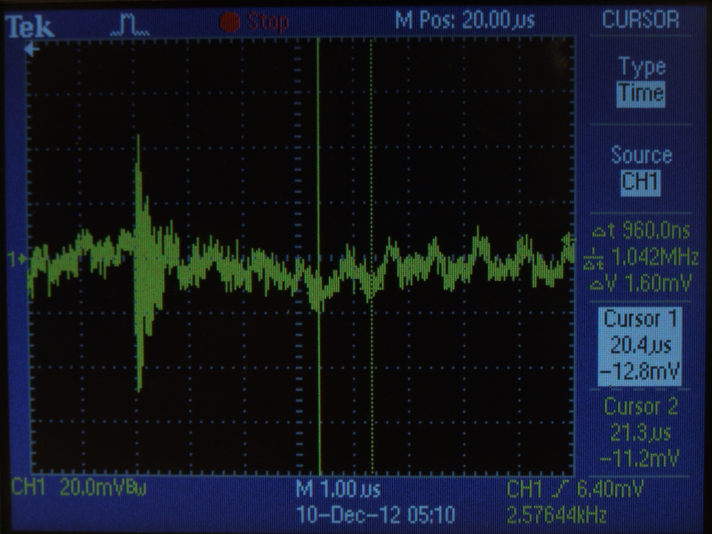
Leading me closer to the culprit was the fact that the behavior was basically the same as hitting the reset button. It took a little while of sitting and watching the 5V rail, but finally I saw a strange transient:
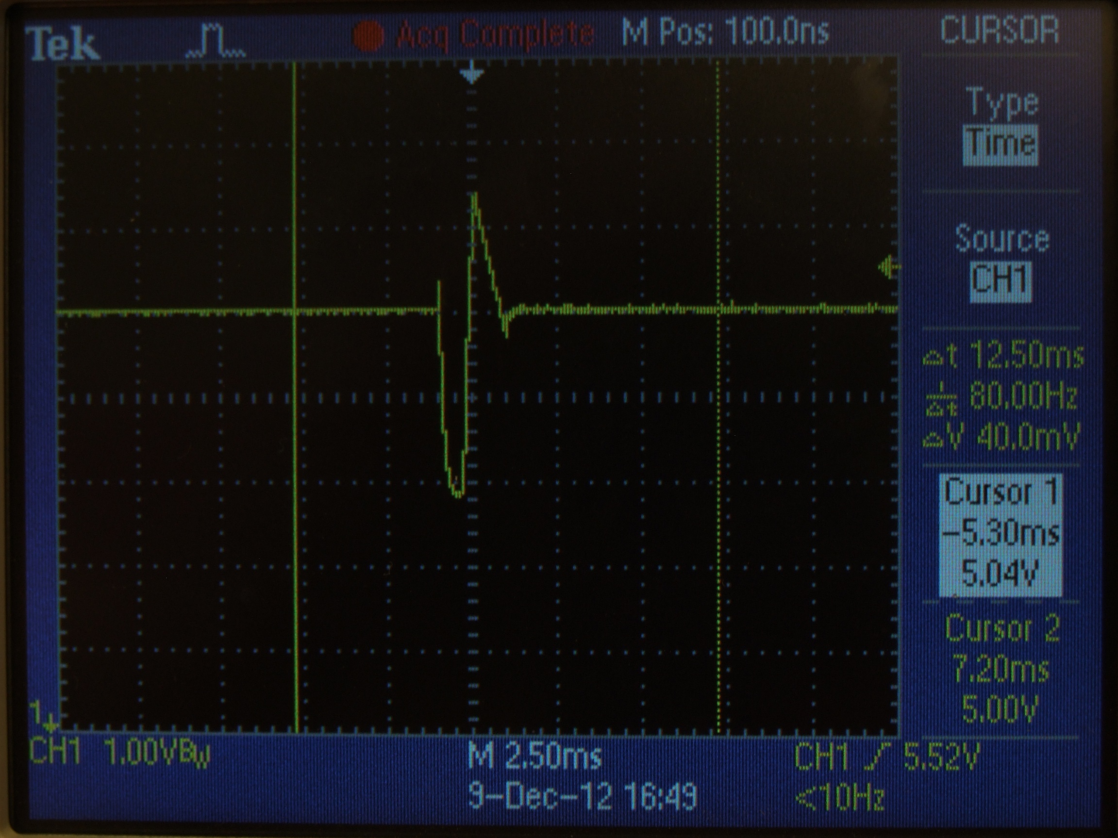
Wow. That’s my 5 volt bus dipping to about 2.8 volts, then flying back up to 6.5 volts. Something weird was happening.
The critical clue was seeing this transient occur whenever the board entered running mode (i.e. left failsafe mode). It also happened immediately after reset, before the program has a chance to load. The transition from running to failsafe mode was smooth, and by pure accident, I left the USB cable plugged in (while trying to mess with the code to see if I could get the reset to occur elsewhere) and noticed this transient did not occur. I could, in fact, “bootstrap” the board with USB power, then after it enters running mode, unplug the USB. And it will be fine.
It was clear to me now that it was caused by something suddenly wanting a ton of power from 5 volts. But what? The microcontroller doesn’t need that much of a load at the start.
The only thing that happens when the board leaves failsafe mode is that the gate drivers are enabled. Could that be the problem? I began to suspect that the sudden current demand of all the gate drivers enabling at once caused the boost converter chip to go crazy. To test this hypothesis, I ‘staggered’ the re-enabling of the gate drivers into 2 groups, separated by 5 milliseconds.
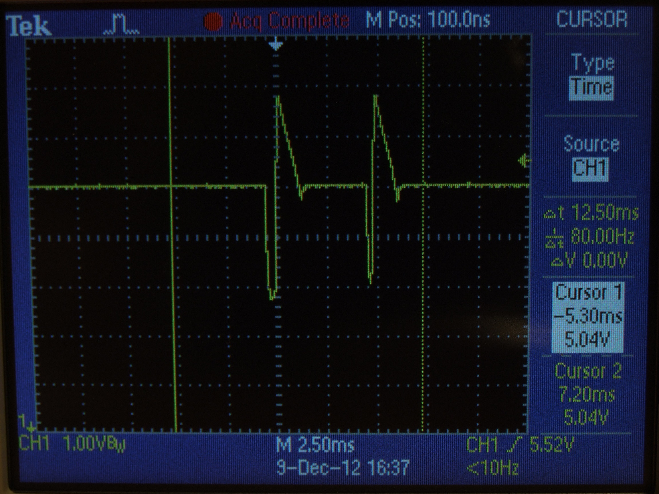
It was definitely the boost converter beating my 5V buck converter into submission now. The fact that there is a transient whenever the gate drivers turned on was the decisive piece of evidence here. What’s funny is, the board worked fine in this state. It seems the sudden pull from the 5V rail is no longer enough (since only half the gate drivers are demanding current) to reset the chip.
The explanation as to why the gate drives suddenly want a burst of current is that the first thing they do when enabled is turn on the low side FETs on all the H-bridges (i.e. feeding a pretty big capacitor in the form of the gates). The bootstrap capacitor for the high side also charges at the same time. A small dip in voltage occurs on the 15 volt bus as a result.
Because the boost converter is much faster than the buck – 1mHz vs. 150kHz, it responds by pushing more current through the inductor (briefly 1.3 amps worth at least, according to the MIC2288’s rating) and it does so quicker than the buck converter can respond. As a result, by the time the buck converter duty cycle catches up, the transient power demand on the 15v bus has already been fulfilled, so the boost converter backs down output current. Again, because the buck converter is slower to respond, it overshoots and then slowly adjusts itself again. That’s how I think it goes anyway.
So basically, I need a precharge circuit or something for my 15v bus. Well, one way to combat capacitor dumping is with more capacitors:
First, I replaced the small 10uF 16v ceramic output capacitor of the boost with a giant 47uF one. On this board, its brethren are buffering the 5V line.
This had very little effect. It seems that the problem is still the boost slurping from the 5V line when it has a sudden demand on the output (necessitating charging up the inductor with a burst of input current). So I moved it to the other side.

This made the transient less in magnitude, but unfortunately it was still causing the ATMega to brown out.
Facing another potential redesign of the board to add even more capacitors or something, I thought about other bad hacks like isolating the 5V power converter from the rest of the logic with a low-ohm resistor, such that even if the converter itself goes under a little, the local capacitors at the ATMega and current sensors, etc. will keep them afloat briefly.
Then I remembered the LT3460 has a 300mA internal switch current limit. The MIC2288 has a 1.3A limit. I began thinking that maybe putting a converter that can briefly eat 1.3A after one which can only source 0.5A (the LM2594) was a bad idea.
The LT3460 has the exact same footprint, exact same feedback resistor and compensator capacitor needs, and exact same output cap and inductor specs. Alright, why not… I’ll swap it in.
That fixed the problem completely. Even with the “staggered start” removed and the extra 47uF of capacitor gone, there were no startup issues. The transient on the 5v rail had declined to the point where trying to detect it was difficult with the scope’s noise floor.
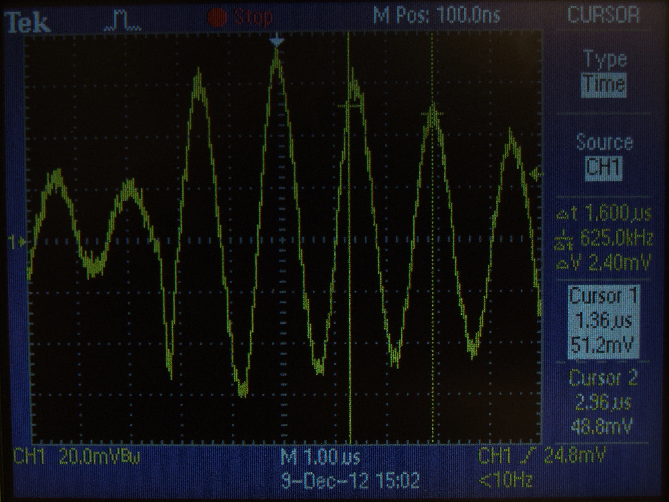
Above is a picture of the 15v rail under switching conditions, when the gate drive is running. As can be seen, all of the FETs being switched on at once causes a brief dip in the power supply (on the order of 0.2 to 0.3 volts). Meh.
I zoomed way in on the 5V supply and AC-coupled the scope to catch the power converter’s actual output waveform. The 1mhz switching freq. of the LT3460 can be seen over the 150khz switching frequency of the LM2594. The 5V ringing is a bit concerning, but it doesn’t seem to be affecting the controller function.
In the interest of reducing this ripple, I’ve spec’d out a 100uF 6.3v ceramic cap just for the 5V rail. It has the same package as the 47uF on there now, so it will simply drop into place. I’m also going to add more bypass capacitance at the ATMega and current sensors, upping it from 0.1uF to 1uF.
I waterjet-cut the updated heat sink plate design for RB and laser cut my remaining silpad sheet to make the insulator. This is basically what a stock RB will look like, without an additional fan mount or something. I’ve accepted a quote for punching out the heat sink design from 1/8″ 3003 aluminum, with a silpad die-cut piece bonded to it. The future is exciting.
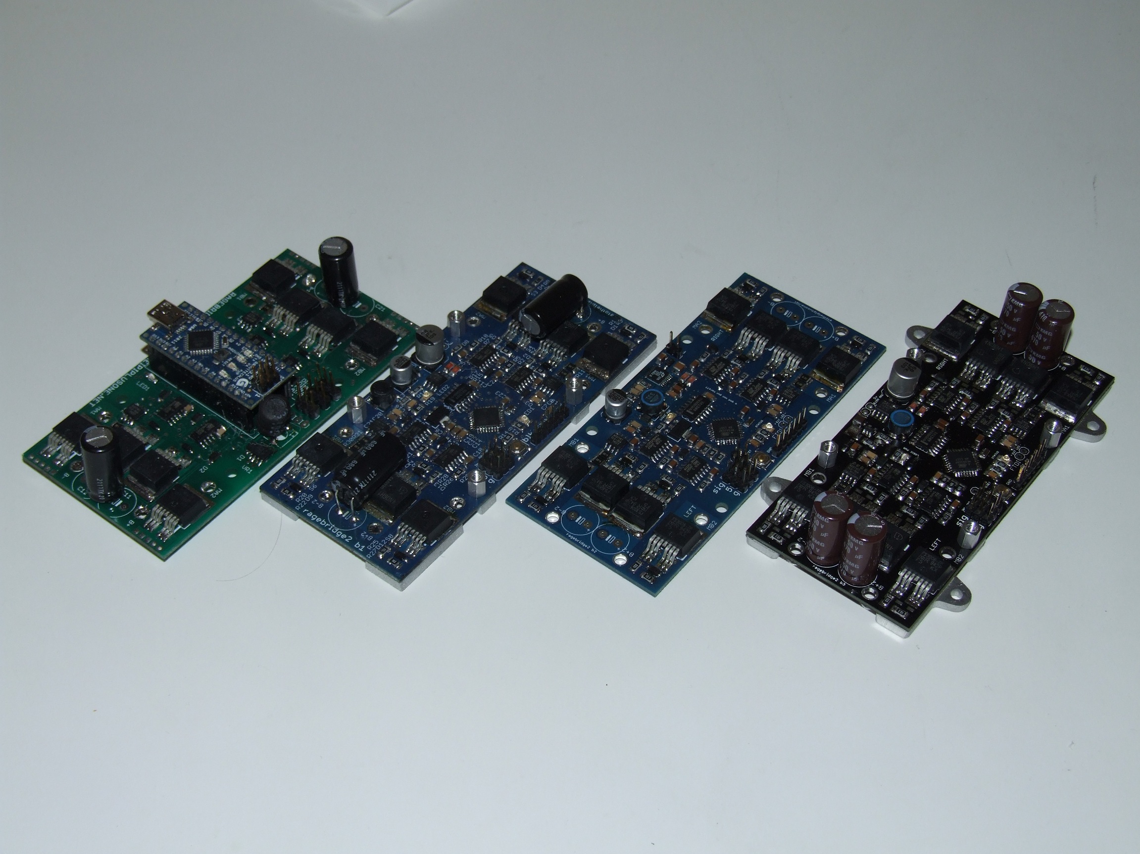
Here’s a picture of all generations of RB so far!
I’m now going to throw this board into something like Null Hypothesis and ride it around drive it to obtain a reasonable robot drivetrain test for temperature and current draw.
In the mean time, I’d like to rally some help from everyone.
I and a few cronies are gearing up to bring a first run of these boards out next Spring. I’ve made a survey to get a better idea of what people actually want to see, featurewise, as well as other details like support and returns. Please take a moment to fill this out, even if you’re not immediately out to buy a big motor controller!
The RageBridge Survey
I’ll be cross-spamming this across a few different forums in the coming days.
I’m very excited for the future as well. It’s impressive to be able to watch the evolution of this device. Thanks for that.
Good work man congrats
but Let’s think out of the BOX for a second
why bother with problems of buck -then boost .. you need the 12v only for gate drivers right ?
why not use a gate driver that operate on 5 volt or at least doesn’t stop working on low voltages ( if it exist ) , the reason is that there are now trench or logic level (vgs=4.5) mosfet with ultra low Rds and not terribly expensive.
isn’t better that your whole board work on 5v bus and easier in routing ?
please consider and correct me if am wrong?
The IR21844 combo is my current ‘stable’ platform, which is why I’ve been developing with it. It is true that there are logic level FETs which can switch at very low Vgs, but 1. I couldn’t find any with good characteristics that could handle 60-75V and 2. They are more expensive than standard FETs at the resistances and voltages I was seeking.
Even some of the Hobbyking ESCs have a charge pump that feeds > 10v to the gate drivers (like the small 4 cell one I reviewed last year).