Wow! Can you believe it’s ONLY been only a month since the last Overhaul 2 D&B series post?? I felt like it was last year. Time flies when you’re trying to finish a robot.
So the truth of the matter is, if you might have guessed, the competition and season filming is already done. Everything was packed up and shipped on April 5th. Prior to that, the build season got hurried, so I prioritized having a robot over blogging – I know, such shame. Now that I’ve recovered, I can finally return to writing the design and build up. The plan from here is to finish up the design and move onto the build process, because now I have a whole new set of content to pre-game – the event itself! Those posts will be released as the show airs, because spoilers.
Anyways, the very last portions of the design for me to reach before “first-plass competion” was the top armor plate. After that, I could go and revisit parts of the design which nagged me or just didn’t seem right.

The nice thing about having a design that’s almost done is that the last few parts are easy to generate. That’s usually what causes me to CAD more efficiently after I start putting some parts down – there’s less of a need to “design” than to “wrap this thing around that thing”. Conversely, it’s the first few parts that really define the function and shape of the assembly, so you can’t really just skip that.
This top plate is just a “follow the outline” exercise, similar to the bottom plate. The anticipated material is 4mm titanium. I allotted that for weight, but might also make one from 7075 aluminum to save another (roughly) pound and a half in case it’s needed.

I decided to open up an air vent in the “giga bracket” on each side right above the SK3 motors, and save some weight by not having the armor extend out over them. From the previous post, one of the things I wanted to have was a cooling fan which pulled air through important parts of the bot – namely the drive motors and motor controllers. A mockup of the fan is shown near the upper right, where there’s a spare cavity in the bot. It’s a 92mm high-speed server rack cooling fan, and it fits almost perfectly between the frame rails.
To facilitate cooling, I also added a ventilation grille feature at the very back of the bot. This admits air through the battery pack area (which is shorter than the electronics deck), which allows it to flow through the motor controllers. The batteries need minimal cooling, if any at all, so their placement in the air path is incidental.
Save for some minor dimensional changes, this was the end of the top plate. You’d notice that the master switches are just kind of hanging out in the open… That will be a problem to solve later. For now, I declared #yolo and moved on to the obviously most important part of OH2 if you listen to everyone else: the ears.

Fun trivia about Overhaul 1 which most people still don’t know: The famous ears of the bot were a 11th-hour, Hail-Mary addition to aid exclusively in self-righting. The bot was pront to becoming stuck upside-down in a tilted position, and the ears forced the bot to always fall straight backwards if overturned. This was due to the clamp arm being very tall compared to the bot’s footprint. The same issue is present in OH2, so the ears make a return!
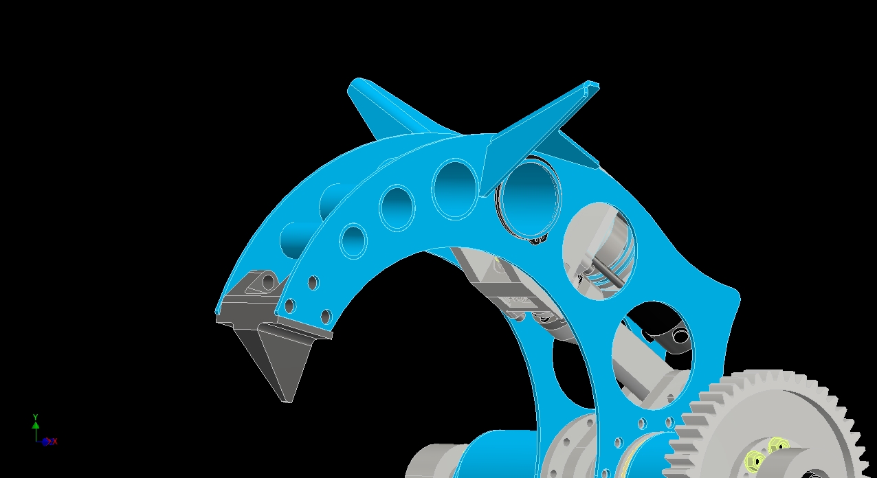
To generate the ears, I first used the model to calculate where the center of gravity of the assembly was when the bot was upside down, and basically rotated the assembly in the view window until I found a satisfactory “line of tipping”. We did this on OH1 with the physical bot, but it was also simple to do in CAD. The idea of ear positioning is to make it such that there is no stable position in the tilted upside-down position because the ears force the center of gravity to act past that “line of tipping”, levering the bot over onto its back.

For instance, in that position, the ‘line of tipping’ is defined by the ear contact point and the back left corner of the frame. The center of gravity acts behind that line, meaning in this condition, the bot will always fall on its back. This hard to “see” in one screenshot, especially in a perspective-eliminating isometric rendering.
The caveat is that this line of tipping is only valid for a certain range of clamp arm positions. I tried to find a compromise with the arm in an arbitrary halfway-up position, like if I was trying to grab Bronco at a bad angle and got wanged (that’s a technical term) over. If the arm were fully raised, there was no position which satisfied the criterion, so like in OH1, I always need to make sure that I begin powering the clamp arm downwards as soon as I think the bot’s about to go over.

Using the “best guess” without an ear already in place, I generated the shape using the side of the clamp arm as a reference plane. Like OH1, the ear will be a bent plate weldment attached to the side of the clamp arm. Once I had the general shape, I went back and forth in the assembly to tune the dimensions little by little. The determinant was a combination of “stickout” vs. aesthetics – too big and pointy, and it started looking ridiculous. Structural stability was a far lesser concern, since it’s still a large L-section of AR400 steel involved no matter what, but obviously the larger the ears, the more they wrench on the side of the clamp arm.
Trimming a bit of material for weight purposes primarily. The way this will be loaded in the majority is “up and down” from landing, so I was less concerned about the front to back taper being intact.
This is more or less what the final ear design will look like. Now, working on this caused me to remember something that I made a few weeks prior – the big gnawing tooth up front. Remember it from this post? It was made to “have something there” and now I need to think about it again. I was facing down having to get the thing manufactured, or somehow make it myself, and it was starting to be worrysome.

Version 1 of the tooth was a one-piece affair made from a big chunk of tool steel. Version 2 takes the “important part” and makes it machinable from a much more commonly found flat tool steel stock. The total thickness is 1.5″. To make up for the thickness difference between the clamp arm plates, the triangular upper profile of the tooth will just be made into some 0.75″ thick spacers, to be cut out of aluminum.

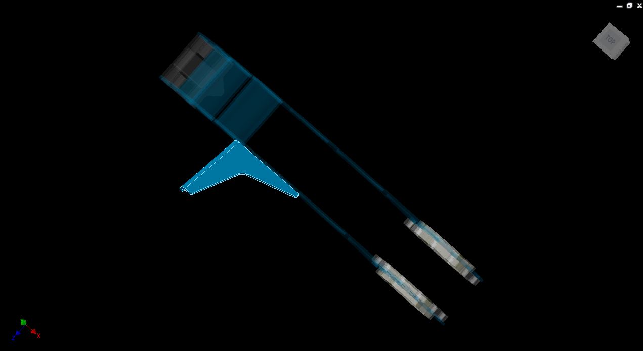
And with that, every element on the bot is “first-pass complete” in some form. Notice that the arms are still the slightly older curved design which I explained in the Pointy Things post.

I changed the color of the pontoons to more reflect the original concept. Short of a few changes made later on during “production”, this is what the final bot looks like.
the manufacturing process begins
There’s a big change in how OH2 will be made that is a departure from anything I’ve done before, including the OH1 build.
What’s going to happen is I’m outsourcing all of the “big machining” – the frame rails, the actuator parts, etc. – to outside machine shops. Not only that, but the large steel parts are going to be laser-cut through a commercial steel vendor. I’m basically only taking care of minor manual operations or “just need 1” kind of parts.
This is a monumental change from everything else I’ve built, where the majority of parts have been made by me, in-house. I’m taking this step for a few reasons:
- I decided that it was worthwhile to trade money for time due to the splitup of team JACD from Season 1 – I could no longer count on equally-skilled friends who can take a CAD file and go make it, then come back and keep working together. My team this season would be more “minion” than anything else, so I had to make sure the complex-skilled tasks were taken care of.
- If I chose to do all the machining myself, I would have to be literally machining from now until the season, on machines which I could not guarantee that I had consistent access to. Factored in with leaving MIT proper, and I couldn’t guarantee that I would be able to machine anything short of using manual machine tools.
- Equals Zero Designs still needed my attention and I’d rather be spending as much time as I can making sure RageBridge 2s didn’t have too many teething problems or manufacturing issues popping up in the field.
What this means is that the relative cost of the build was going to go up immensely, even with my contacts at Chinese production shops. I estimated each frame as being around $5,000 of machine work, and obviously needed more than one frame for spare parts. That’s always a trap with building bots – you never really build one robot, but more like two or even three, because what’s the cost of losing a match because you did not have any spare parts to restore functionality with?
Overhaul 1 was built for an all-up cost of around $9,000. With the machining estimates for both the aluminum frame and steel armor plating, I was looking at a minimum cost of $16-18,000 if not more. Oh boy, glad those RageBridges are selling…
I put togther a package of detailed drawings and accompanying models, like the one seen below for one of the frame rails:

Techinical drafting instructors and machine shop foremen, start cringing.
I play very fast and loose with my drawings – basically if it gets the point of the part across, it’s fine by me. One of the upsides of working with a “bot vendor” like Team Whyachi is they “get it” – combat robot parts tend to worry much less about precision and rigorousness of dimensions, because after 1 hit, it won’t matter any more. But it’s hard to communicate that to a local machine shop.
The package of drawings was shopped around very briefly to a few places I’ve had work done with before. It was furthermore segmented into a few parts – the big aluminum frame, and some smaller but still critical pieces like wheel hubs which I wanted dozens of in order to ensure the supply of spare wheels. That way, if a shop had time for the frame, they could take that, but if one didn’t but could still run smaller parts, they could have the smaller hardware.
The bigger your production run, generally the more attention you get from a shop. Small, quick turnaround one-offs are about the worst possible pieces you can have hired out. Companies exist which specialize in that realm, but I can’t afford them :P
While awaiting word on quotes and lead times, I began to put together parts to be made locally. For example, the electronics box (revision 1) layout for waterjet cutting is below.

The plan as of late January & mid-February was to perform the support work in-house and using MIT equipment I still had access to, assemble all the electronics, motors, and batteries, and integrate them the same week that I should hypothetically receive my parts in mid-March.
As a preview of things to come, the first parts to return were the drive wheel hubs, made by a local (Boston-area) CNC shop I had done some business with a while back…

Aren’t they gorgeous? In the next episode, we’ll see how they go together…
In the mean time, if you haven’t already, make sure to Like & Subscribe!™ the Equals Zero Robotics facetube.