There’s lots of variations on the phrase “80/20” – usually it’s some corruption or adaptation of the Pareto Principle, bent and shaped to your specific industry. Legend has it that 80/20 framing got its name from having 80% of the strength of a solid bar of aluminum of the same outer dimensions, but at 20% of the weight. I think it actually weighs a little more than that, but even according to 80/20 themselves the name is just derived from the classical “80% of the results come from 20% of the effort”.
Now, in terms of hours spent building this version of Chibikart, I don’t think I’ve even come close to that. I’ve probably spent around 4 or 5 hours staring intently at a waterjet head versus maybe the same amount actually putting parts together and fabricating. And if I factor in the many hours spent stewing over little details in the design, like how to shove brakes onto this thing, I’m even worse off, probably closer to 20/80…
But what I’m trying to say is, 80/20 is awesome and being able to pitch so many parts of DPRChibikart together in a single day sure as hell makes it feel like I’ve gotten 80% of the way there…. if only. I’ve been taking some notes and modifying the design to make the assembly steps easier. I’ve also been finding that some of the parts I specified in the design are not as appropriate as I had imagined, and while I would totally just modify or custom-machine a part to fit the bill better, having to find a workaround that is a repeatable process by others is challenging as well.
First, a brief recap showing more Pretty Instruction Pictures and some more completed subassemblies.
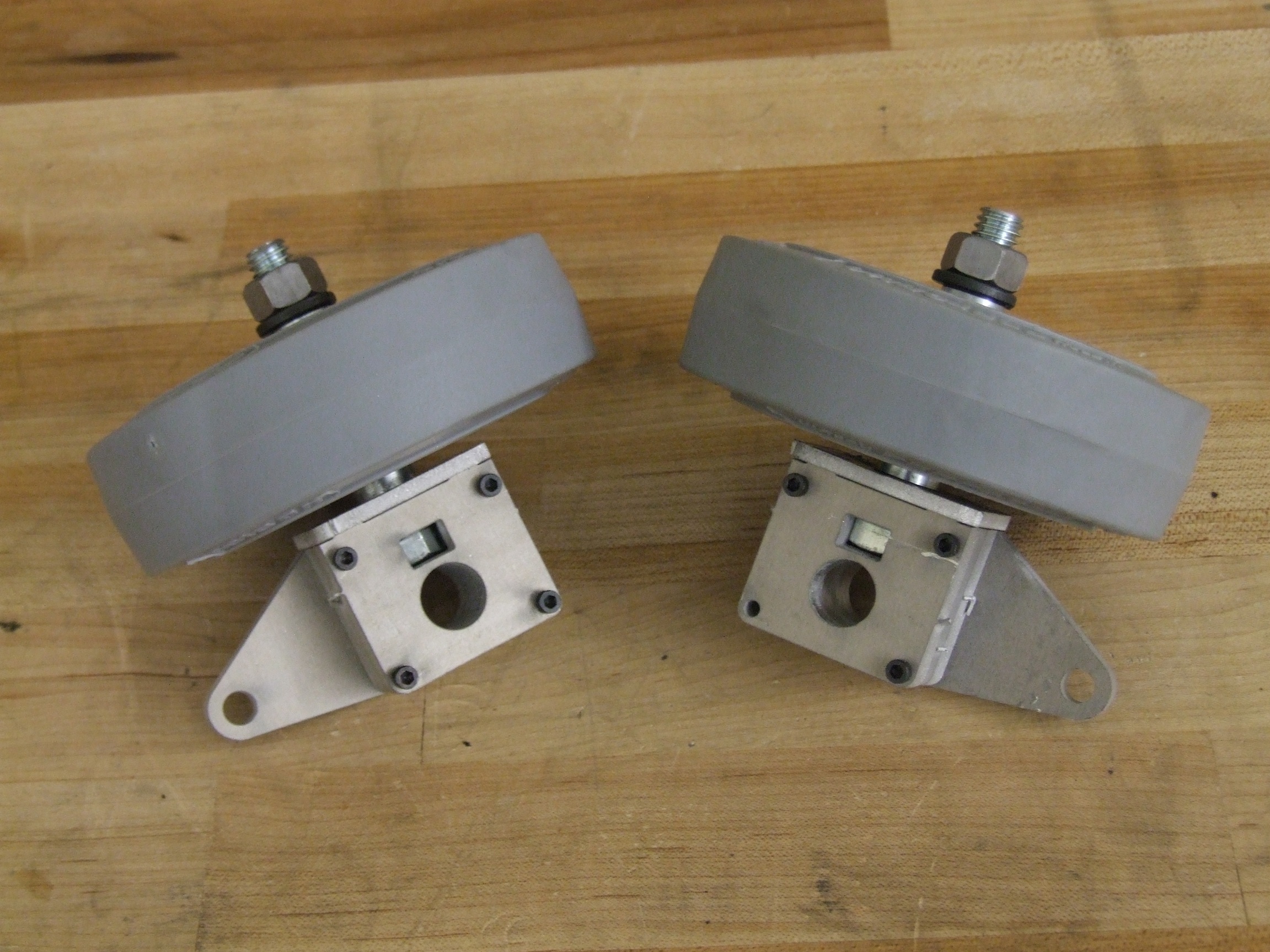
I put together the “uprights” for the front wheels, and I must say that I’m really proud of these. I had expected some fit issues with the head of the bolt and generally keeping everything together, but once I tightened down the 4-40 screws which lock the layers together, and tightened the wheel spindle bolt, the whole thing was rock solid. I have no doubt this will be able to carry any reasonable load DPRChibikart will experience.
My intent with the eventual Instructable isn’t so much presenting a step-by-step of how to build Chibikart as putting together a sneaky way to present resources and techniques while applying them directly to an example build. I’m convinced that said resources and techniques will be way more useful to people than building the whole kart will be – it is going to cost a ton of money and you can readily extend the concepts to your own weird vehicle anyway. Making the uprights for a kart is generally one of the harder things to do – right angle part mates are almost always more difficult to make rigid (short of welding, I suppose), and this will be one more page in the book of tricks.
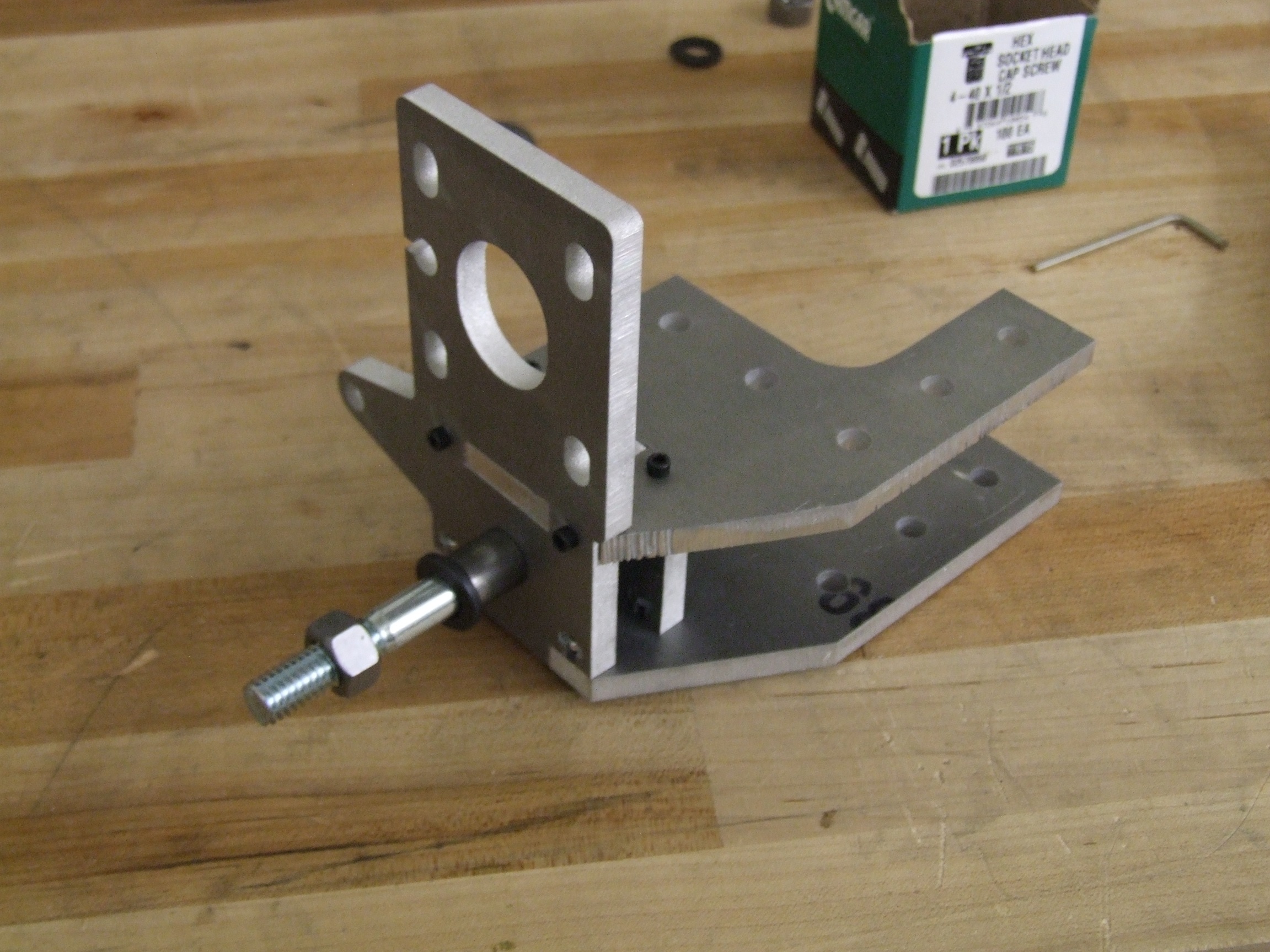
The rear motor mount/corner modules also came out as expected. A small amount (<10min) of file-fitting was required, but I think the tolerances on these slots is more than reasonable given my experience with different waterjets.
When the wheel is clamped by the spindle bolt, the whole thing becomes rock solid and all the parts are constrained by screw pressure – nothing can come loose and slide off, for instance.
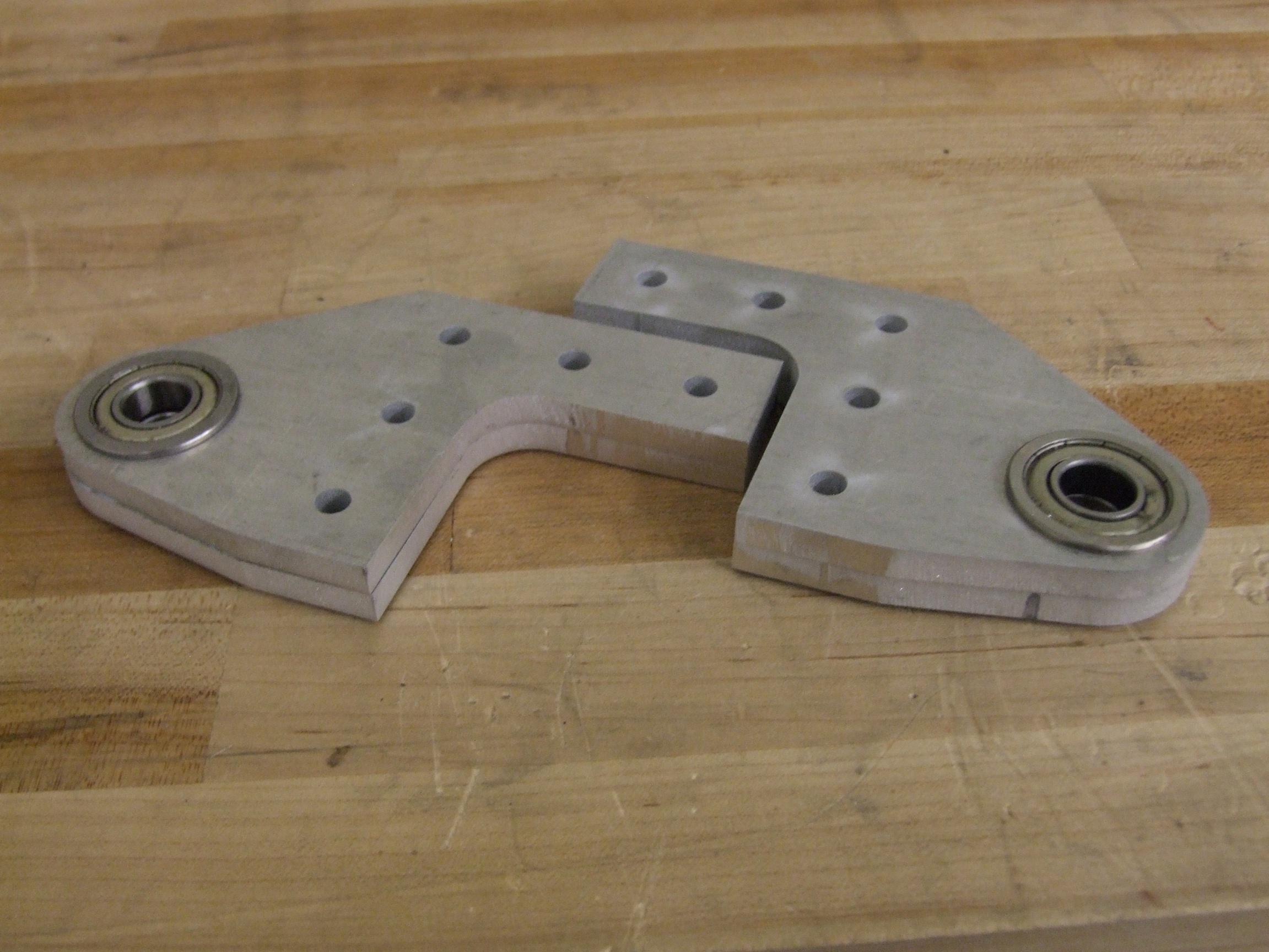
One of the fine tuning details I was playing with was raw-waterjet bearing fits. Normally you would precision bore the hole on a milling machine to get a proper bearing press fit, but if you know the qualities of the machine you use well, then you can make a bore which is natively the right size. However, this is a very risky procedure because then your parts are not gauranteed to be duplicable on anyone elses’ machines.
Hence why I will elect to keep these steering kingpin bearing bores oversize than risk having them be too tight of a press fit, even though they were just right for me. Because these are flanged bearings and the kingpin will keep them tightly bound together, there is almost no need for a tight press fit. It could even be sort of jiggly to start with, held in place later by loading.
Cool assembly methods will not be the only thing in the Instructable. I intend to put a healthy amount of manual fabrication tips in as well – the first of which is DON’T TRY TO SUPERMAN-GRIP YOUR PARTS AS YOU DRILL THEM.
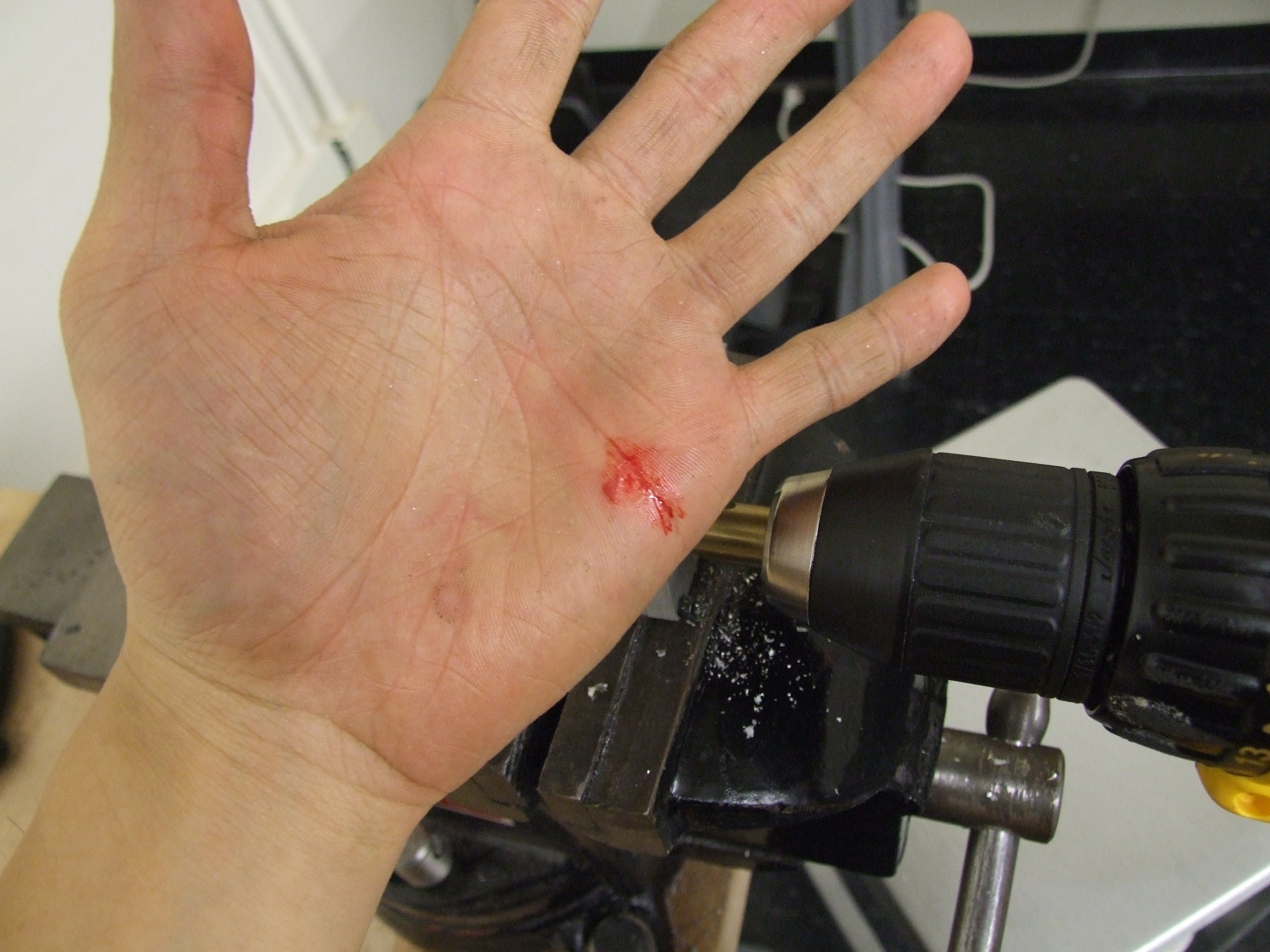
I was reaming out the kingpin holes in the uprights with a 1/2″ drill bit when it suddenly bound and whipped the whole thing out of my grip. Not bad damage at all (and I jut kept working), but I stopped to think a second about what I’m having people do with tools, and how tools can eat you.
The remainder of the holes were done with the upright securely locked in a vise.
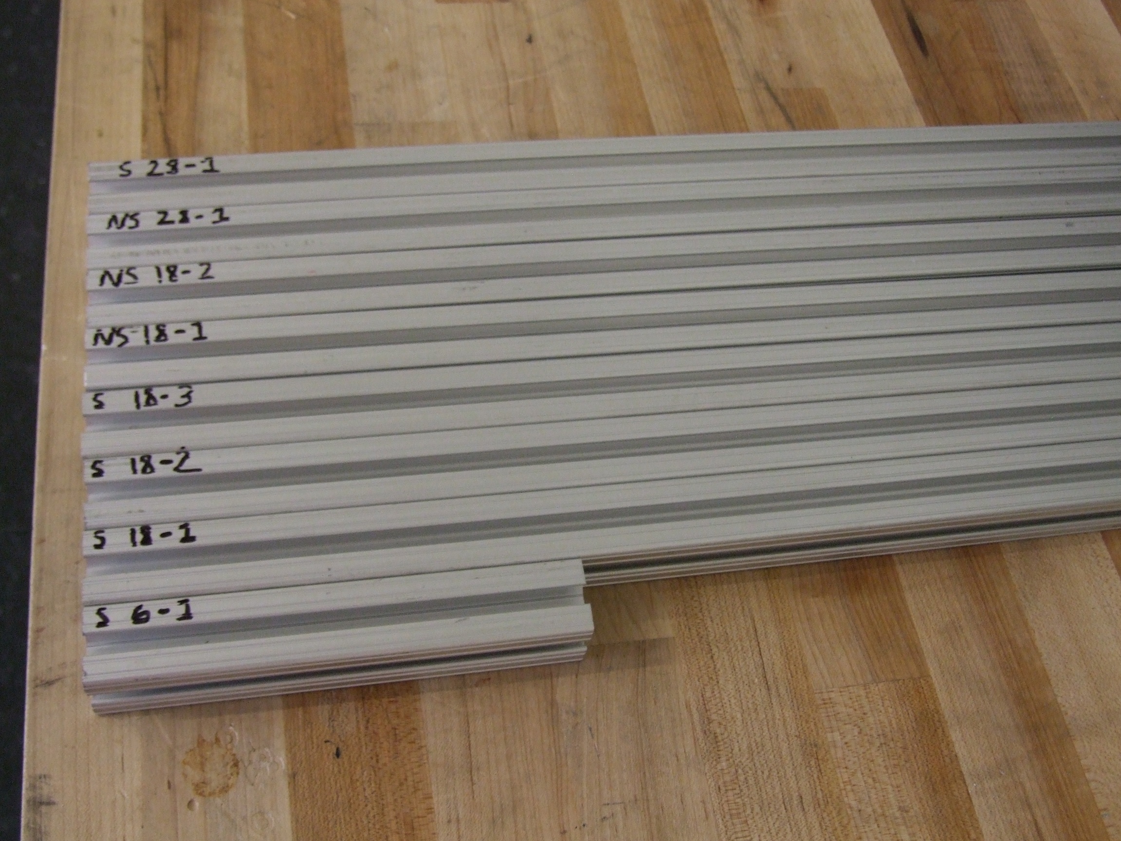
After finishing as many subassemblies as I could, I started cutting 80/20. Normally this would be a horizontal bandsaw (“drop saw”) operation, but did I have a horizontal bandsaw in high school? Not really.
So I hit these with the Sawzall. Very brutal and surprisingly clean and straight. The “S” indicated that the section was cut starting from a clean square end of 80/20, which I deemed critical for some alignments. “NS”, of course, then stands for “Not Square” – a piece which won’t be involved in any end-fastening.

Alright, with all of the freestanding subassemblies done, it was time to to assemble the frame! Here’s a shot of everything so far, along with the ‘critical hardware’ needed for the procedure. This will probably be a theme in the Instructable: necessary materials/parts, tools, and fasteners will be listed, with allowable deviations also listed. If there’s more than one way to make a part, then I’ll try to discuss that too.

Magic happens, and here’s the whole frame. 80/20, anyone?
If I didn’t stop every 15 seconds to take a picture, this would have been an under-1-hour job.
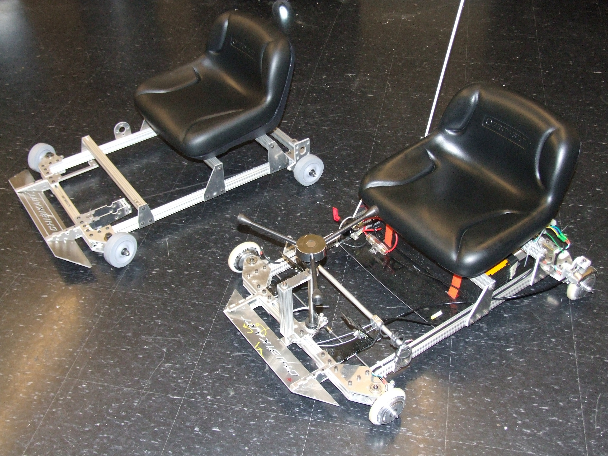
For kicks, I rushed ahead a little and put the wheels on. This is not a step, but I just wanted to see how it looks compared to Chibikart proper (would it be the Republic of Chibikart?). I was missing some critical nylon and bronze washers at this point, so I called it a night here.
If you’re paying attention, you can clearly tell by the ambient lighting what work was done during the day and what was at night.
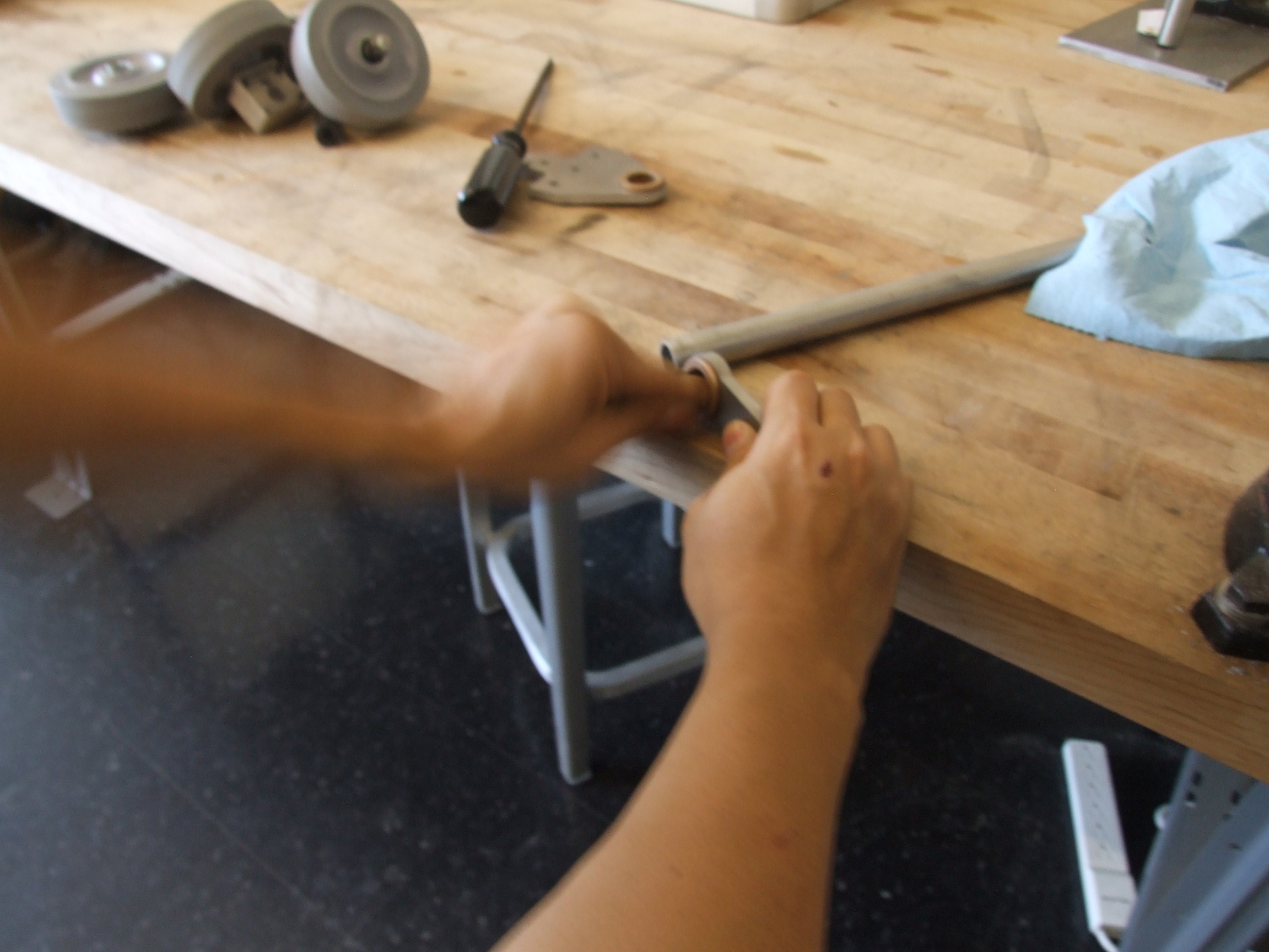
Another day! No, my left arm is not sublimating as I work. This is an “action shot” from when I was filing out the internal bore of a 0.75″ bronze bushing, cleaning up the result with some sandpaper. I should not have found it surprising that raw aluminum tubing is not made to shaft-fit tolerances. I had specified a 0.75″ OD 6061 tube for the steering column, but really it was more like 0.76″ or so.
While I wouldn’t have had second thoughts boring out the bushing on a lathe (and in fact did for Chibikart, just forgot), I realized I wasn’t allowed to do that. So, elliptical filing action it was. This was how they USED to make bearings, dammit.
I will most likely make a note in this step that intsead of using aluminum/steel tubing, McMaster sells precision aluminum shafting in 0.75″diameter which would natively fit in such a bushing. It would weigh significantly more, but aluminum is light anyway.
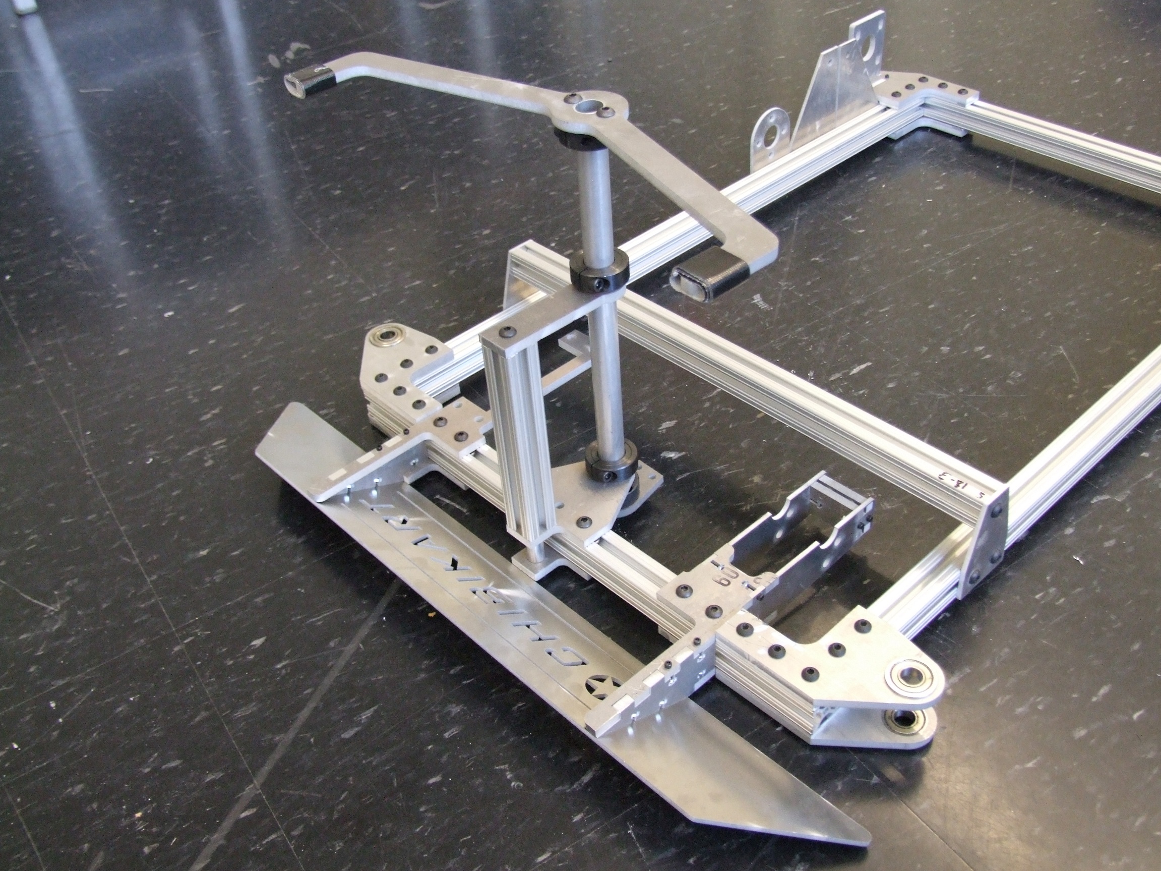
After the steering parts are assembled…
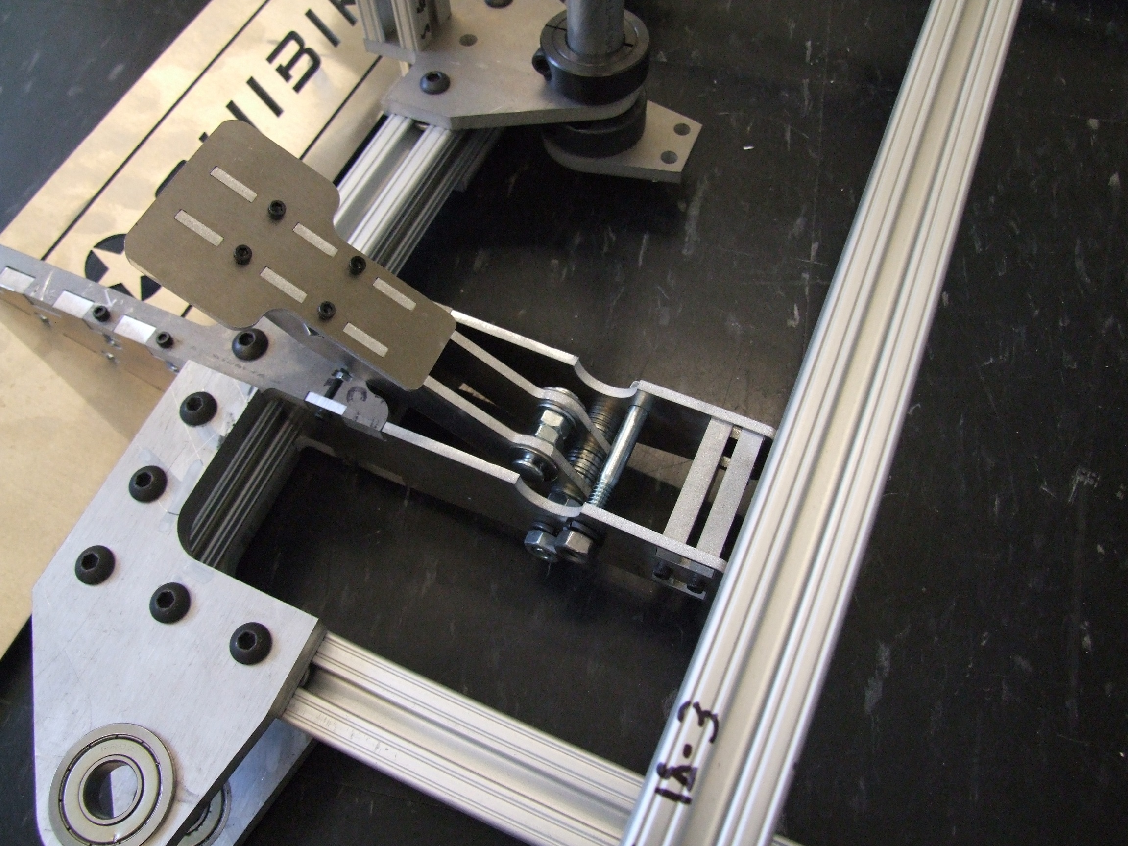
The brake pedal came out nicely. I only had one concern, and it was that the vertical pieces are way too close together. I specified their distance based on a scooter brake-holding-cross-drilled-screw-thing that I already had, which was pretty short. I then lost it, so had to source new ones from Cambridge Bicycle. It turns out that bicycle caliper BHCDSTs are usually alot longer, and I wanted most of these brake parts to be sourceable from bike shops for repeatability. I may make an untested design change for the Instructable in which the pedal itself is made wider to accomodate different length screws. It would also cut down on the sheer number of washers I had to stack between the plates…
And the front end is off the ground! Putting together the steering involves cutting some allthread, which I did using a hacksaw. Man, it’s been a while since I hacksawed the shit out of something.
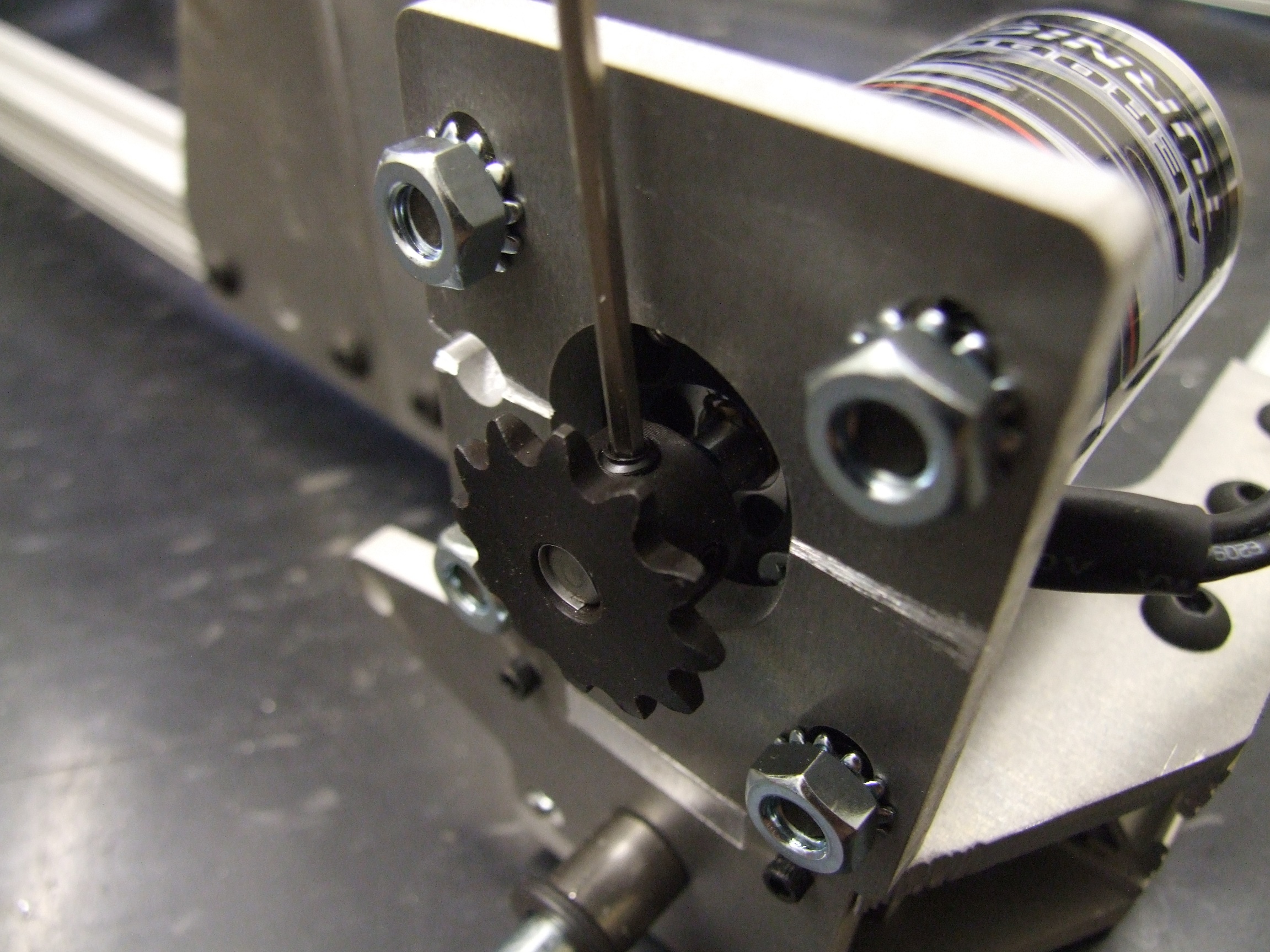
Mounting the sprocket on the motor was a chance for me to finally use a mostly bullshit tactic that I had been saying to people to get them to stop asking questions. Yes, that’s a chunk of a soda can hanging out of the sprocket there. I’d jokingly suggested to people before that soda cans in fact are sources of precision shims from 0.004″-0.006″ and that they can be used as crude metric-to-imperial bore converters if needed.
Well, I’m not joking any more. I measured the can wall of a Sprite Zero at 0.0045″ +/- fuck, this isn’t 2.671 near the 1/3 mark. 6mm is 0.236″, and 0.25″ is… uhhh, 0.250″. So there’s about 0.007-0.008″ per side to make up, or 2 full turns of soda can. Procedure: Cut small strip of soda can, wind into coil, stuff into sprocket.
Note that the thickness increases near the endcaps due to the drawing process, so if you need a thicker shim, you can cut closer to the ends. The can walls are thinnest in the middle, which according to my old 2.671 Soda Can lab paper is about 0.0041″.
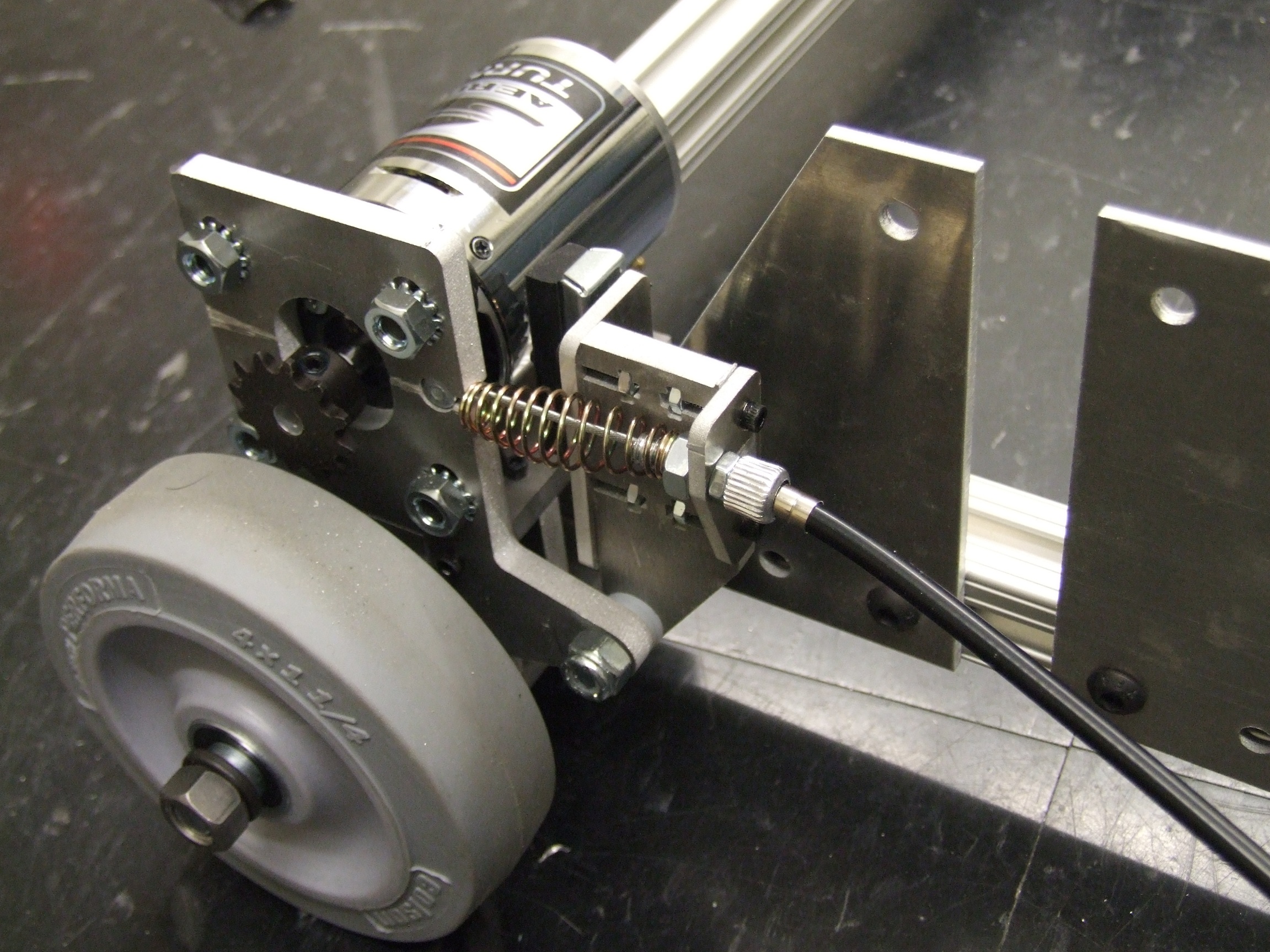
To add to the list of things I’m really proud of on this build, these half-caliper half-railcar brakes came out pretty awesome. The circular notch holds the little cable-end-ball-thing of a road bike brake cable. A general cheap road bike brake pad is the friction element, and the cable-tension-adjusting-hollow-bolt-thingie is also sourced from a road bike caliper brake.
I spent an incredible amount of time just learning what these specialized bike brake parts were called. I’ve gathered that:
- “cable-end-ball-thing” is a nipple
- “cable-tension-adjusting-hollow-bolt-thingie” is a barrel adjuster
- “brake-cable-holding-cross-drilled-screw-thing” is an anchor bolt or pinch bolt.
So yeah. If you want to pre-buffer parts, go get two standard road bike brake cables with at least one nippled end, two smallish brake pads, two barrel adjusters, and two anchor bolts. Use the proper terminology so your bike shop guys don’t give you the “wtf?” face when you literally use those Buffy-speak names.
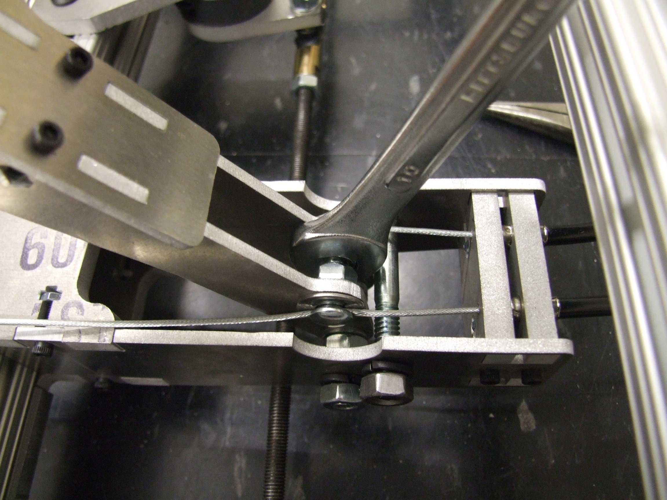
Clamping the cable this time is much, much easier compared to the fiddling I had to do with Chibikart’s brakes, which didn’t use brake-cable-holding-cro ANCHOR BOLTS. The waterjetted cable sleeve holders also worked out very well, requiring no drilling or messing with.
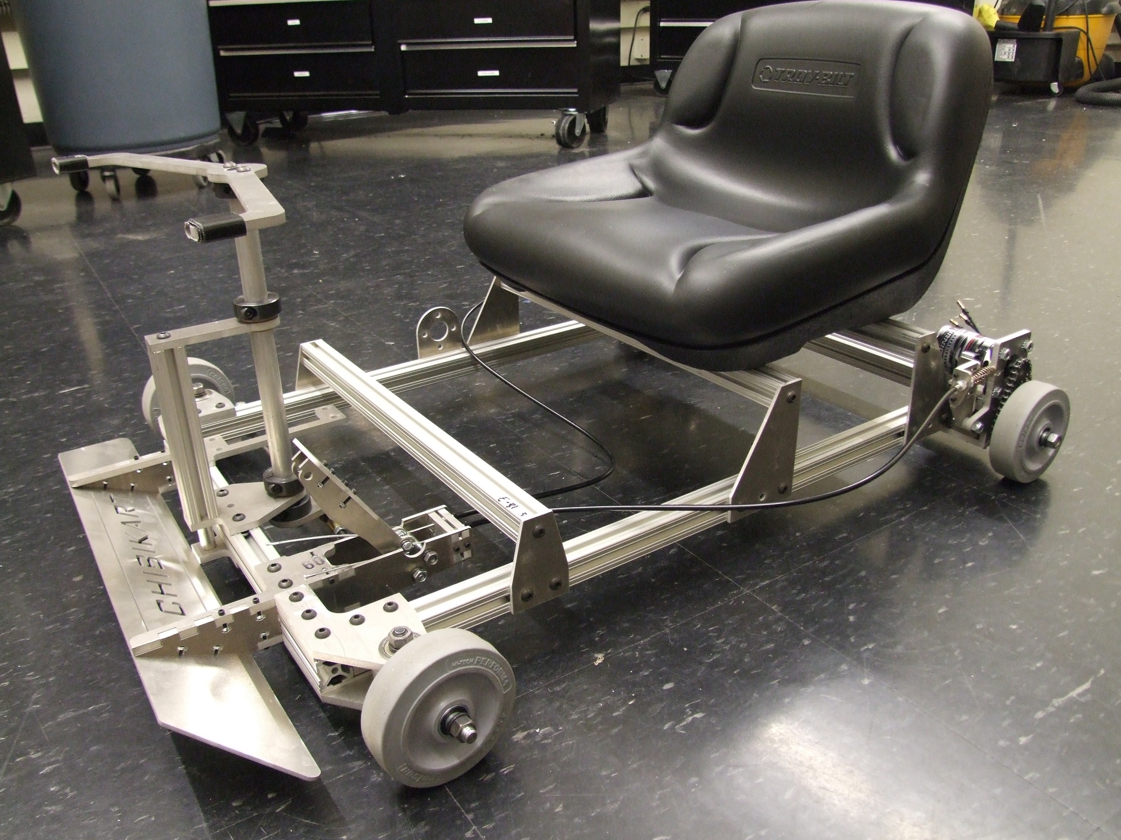
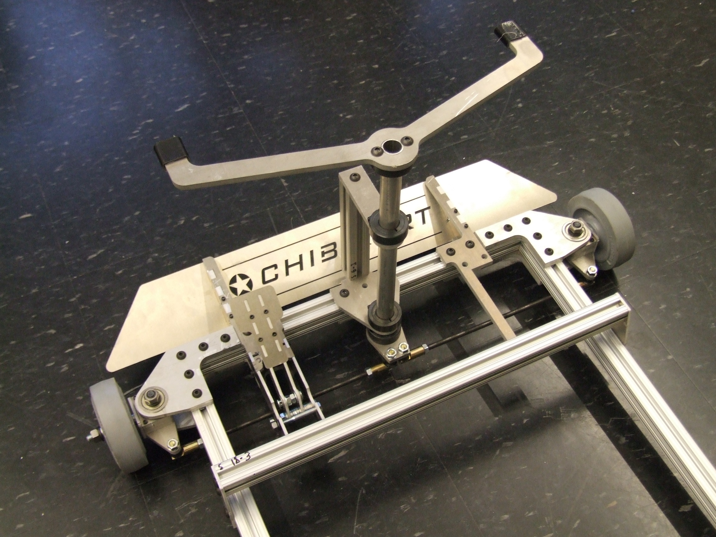
BAM! Rolling frame.
The brakes on this are obnoxiously good. Probably because I overcompensated since Chibikart proper had no brakes to speak of until 2 weeks ago. This will lock up and skid with 65A durometer Colsons, which means if I fit hard wheels on the back it will drift readily. This is exciting.
What’s left but to have your friends push eachother around while looking silly?
Here’s what’s left.
- Assemble the electronics plate. This involves waiting for a new shipment of Jasontrollers, which should arrive this week. If they don’t come by Wednesday, I might actually knock two Jasontrollers off Chibikart for now just to get it over with. Because I want to ride it. Badly.
- Put all the pictures into rough assembly order and make smaller sizes of them, because there are currently 235 of them. Not all will be used, but most will be!
- Write the damn thing. I need to start now if I have any hope of finishing before the Make It Real Challenge is over!


