This is a brushed Etek.
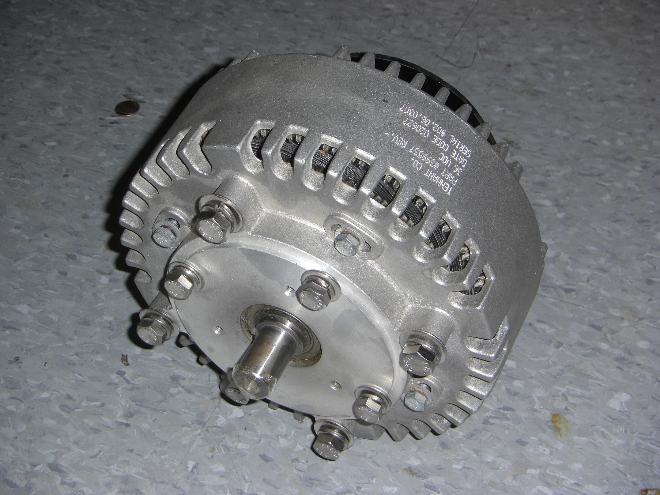
It is an axial air-gap ironless disc-armature rare-earth permanent magnet DC motor. That’s a mouthful, isn’t it? Thus it is commonly referred to by its acronym, “AWESOME”, which is pronounced “badass”.
I traded in the brushless Etek that I was running before for this thing, mostly because brushless motors require nontrivial power electronics to operate, and we know my luck with nontrivial power electronics.
The brushed DC motor requires… you know, DC. Conveniently supplied by the kilo-asston by large nickel cadnium batteries.
Additionally, the brushed Etek is capable of high power throughput than the new brushless motor. Some times you just need a dose of old-school brute force.
Speaking of nontrivial, I had thought that swapping the motor out would be a 1:1 operation, as the two were designed to be interchangeable.
Sort of. They’re designed to be compatible only if you’re mounting through the face of the motor and nothing else. They are drastically different lengths. This is a bit of a problem when you fit the motor exactly between two walls of aluminum that are now static.
To make life even more interesting, this was the original robot version of the motor – which had a short, 3/4″ diameter shaft instead of the normal longer, 7/8″ shaft. Problem? My sprocket was purchased for a motor with a 7/8″, long shaft.
So it turns out that changing motors was going to be less than trivial. No problem, however, since I’m better at navigating the seas of mechanical nontriviality. In a pinch, you can use a slide rule as a sextant.
The motor mounting spacers would have to be shortened half an inch, and the sprocket would need a bore adaptor to fit it to the 3/4″ shaft. Additionally, I would need a wider key to take up the 1/16″ bore difference.
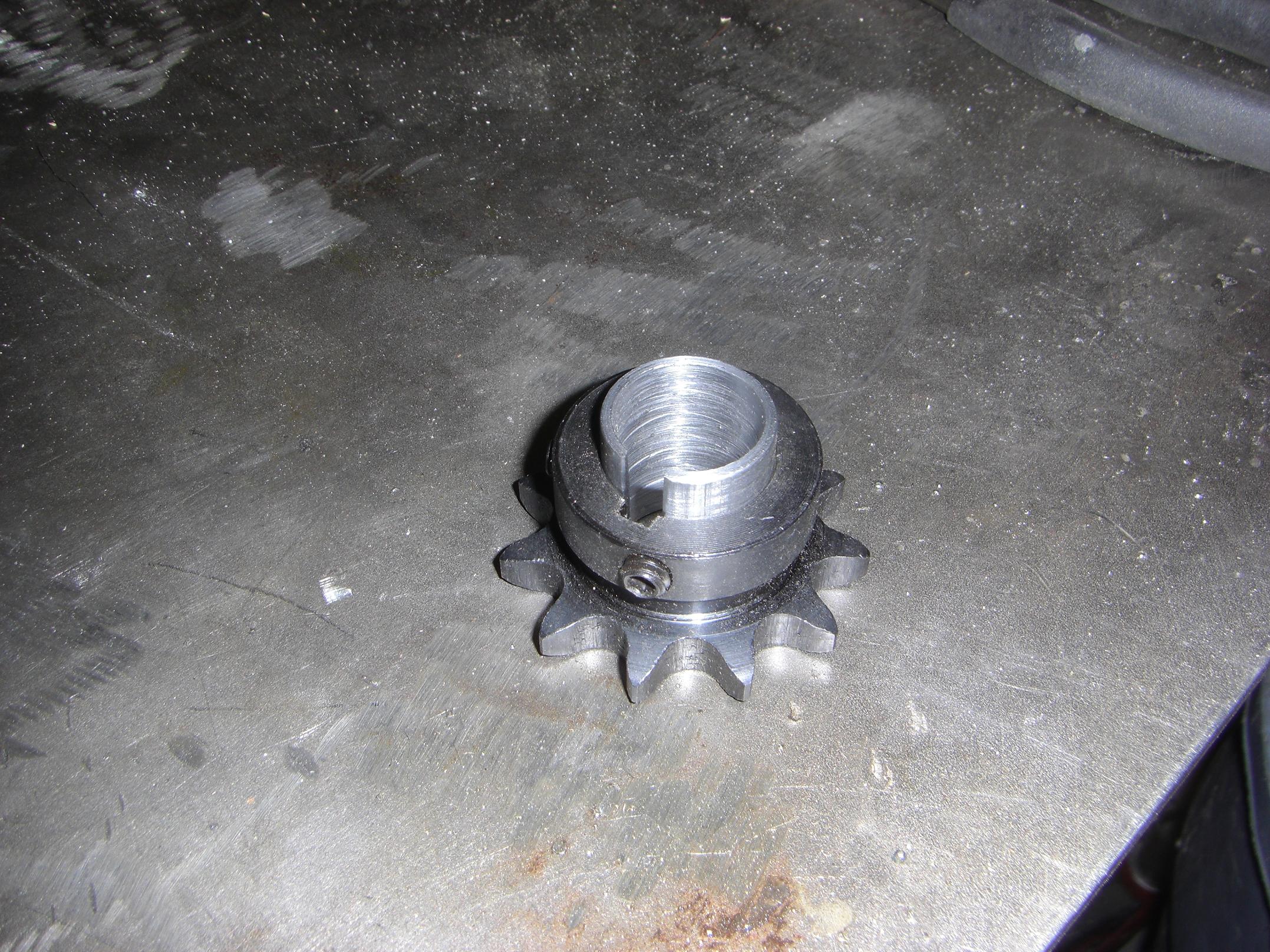
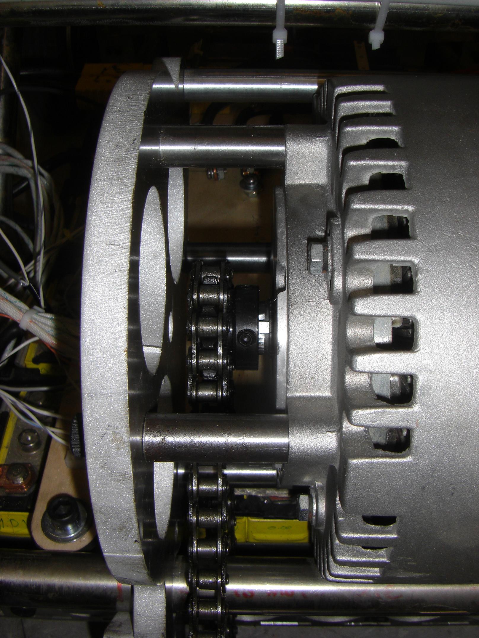
Here’s the sprocket with bore sleeve. I searched the entirety of MITERS for a 7/8″ OD pipe with a .75″ or smaller ID, but couldn’t find one. So, face with no other options, I bored and turned a solid 1″ bar of steel into a little pipe shape, then slit it on the mill.
Sigh.
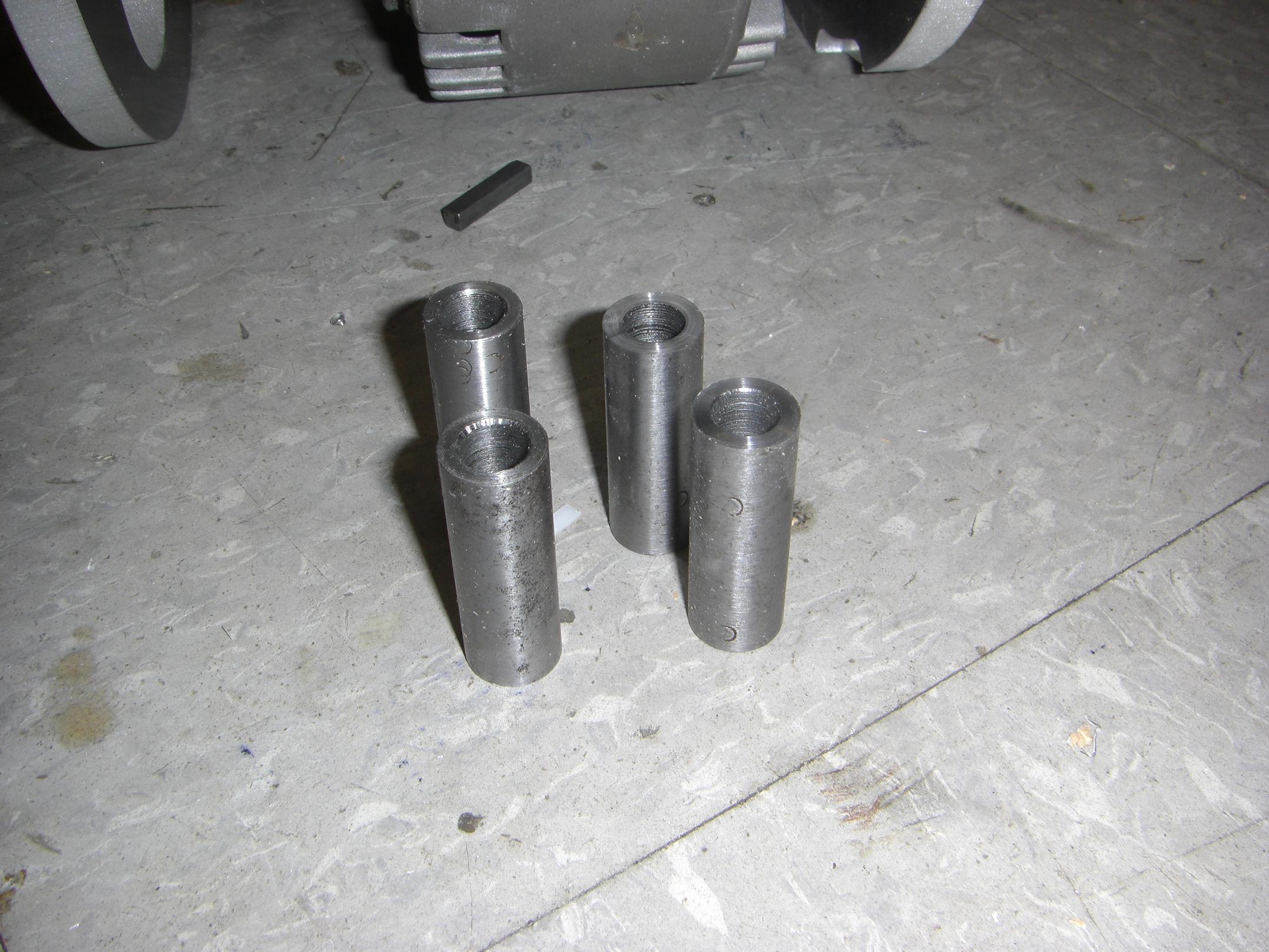
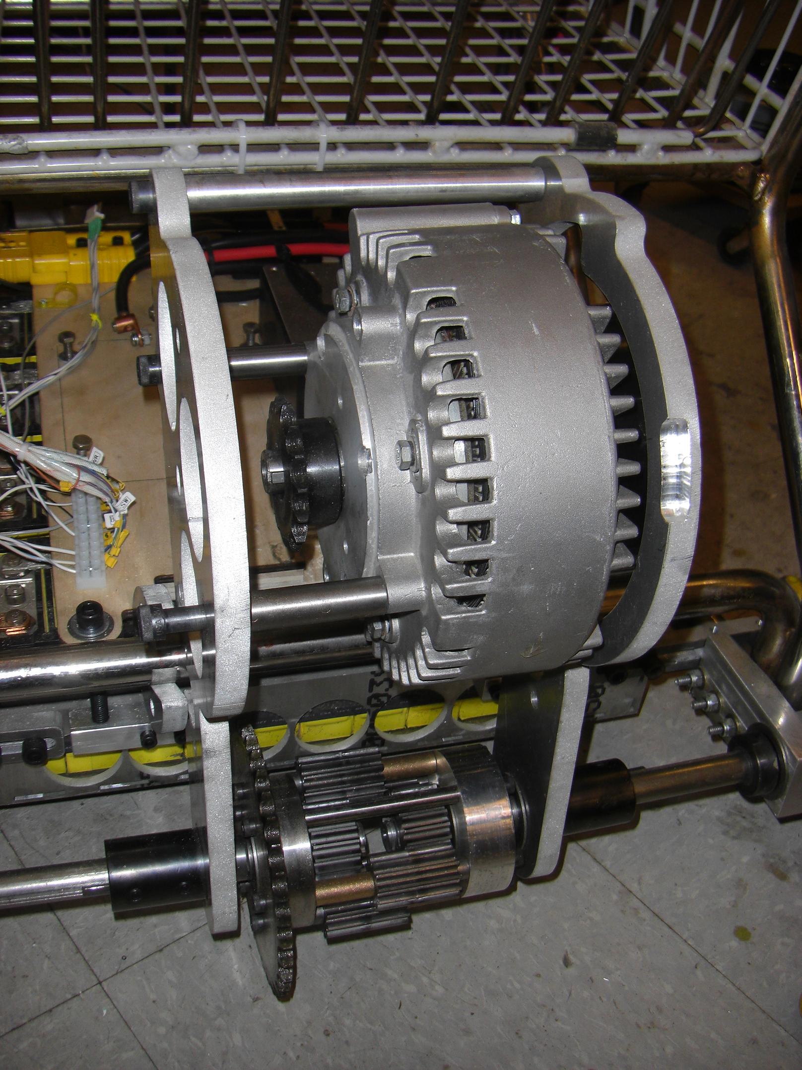
The motor spacers each shaved down half an inch. This is necessary such that 1) the aluminum motor casing doesn’t try to intersect the aluminum transaxle superstructure in 3-space, and 2) such that the motor sprocket can still line up with the differential.
Everything put back. I took the opportunity to move back down to the 11-tooth sprocket, too, for more tire-flaming torque. Unfortunately, this limits my top speed to a mere 36MPH, from 45.
Oh well. Some times in life, sacrifices have to be made. Also, going down to the smaller sprocket allowed me to take a link out of the chain, which was sort of droopy with the 15 tooth sprocket, but was then the *PERFECT LENGTH* when reconnected.
With the motor mounted, it was time to move back to the electrical system.
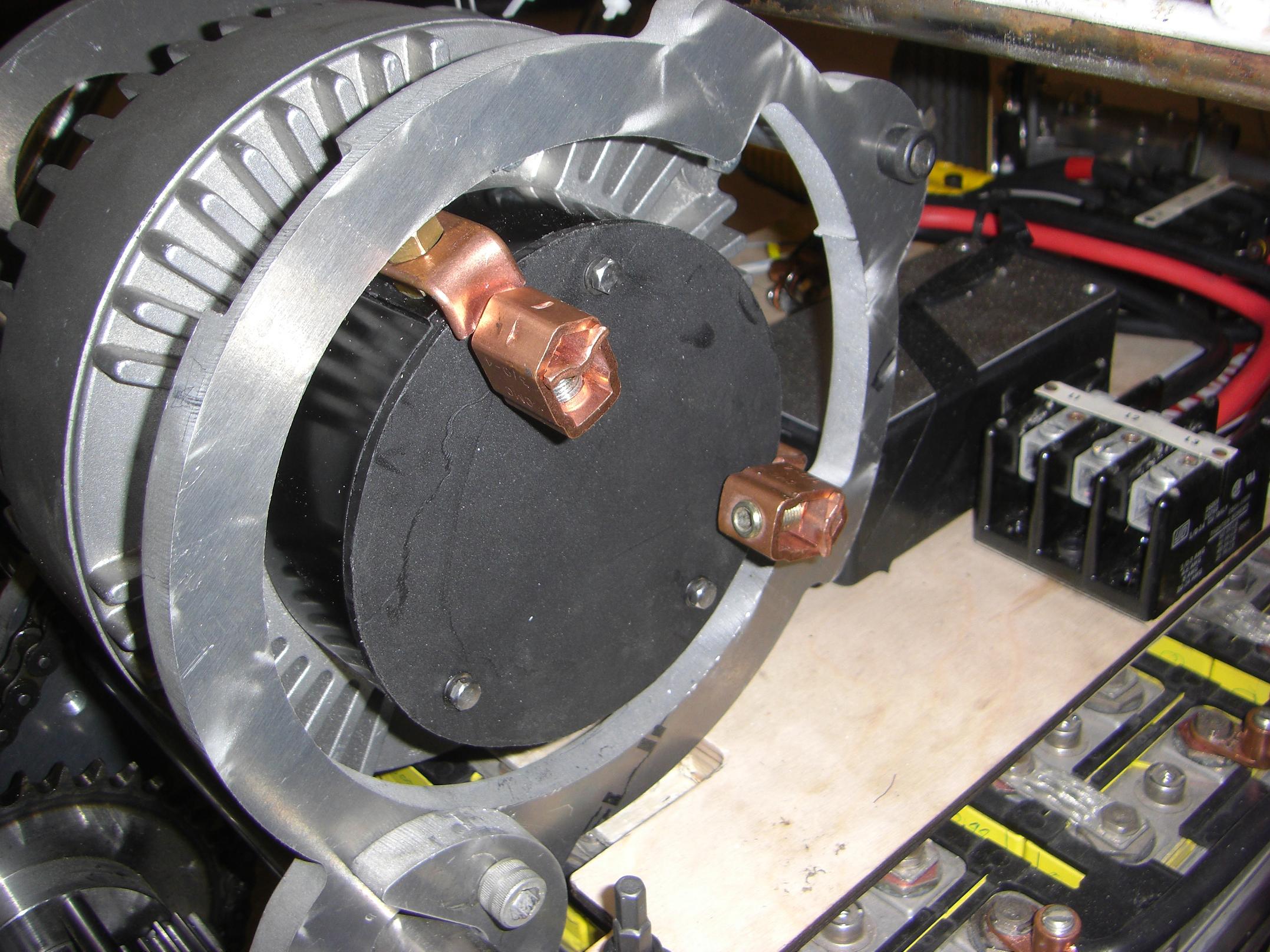
Observe. These are wire connectors for real men. Man-nectors, if you will. The smallest wire gauge these are designed for is 4 gauge, and the largest is 3/0. I was actually looking for more of the smaller type seen on the batteries, but then found these suckers. Such a manly motor requires masculine terminals for maximum badassery.
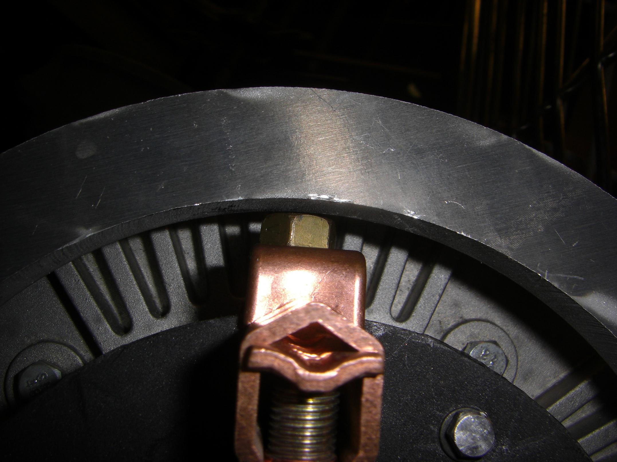
…with the mounting bolt about 1 nanometer from grounding to the frame, just the way I like it.
This was a significant nontriviality in the motor mount that not even moving the motor forward half an inch could help, since the transaxle side thickness is half an inch, and the motor terminals were placed so perfectly as to be covered by the metal both times.
Don’t worry, this will either be insulated or DC arc-sputtered away!
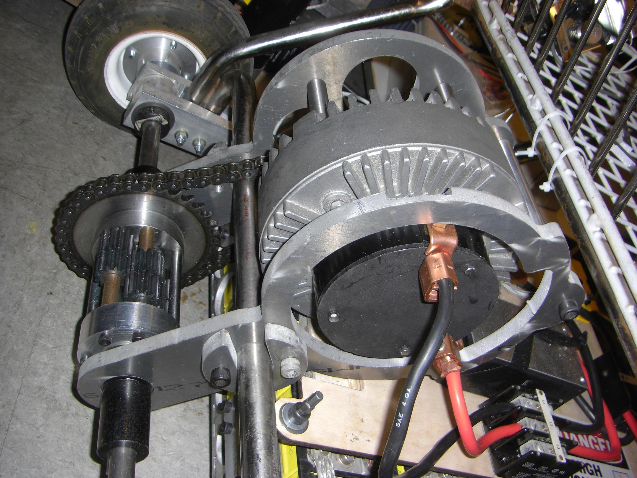
Brushed Etek fully secured!
Okay, enough with making it go – time to figure out how to make it stop.
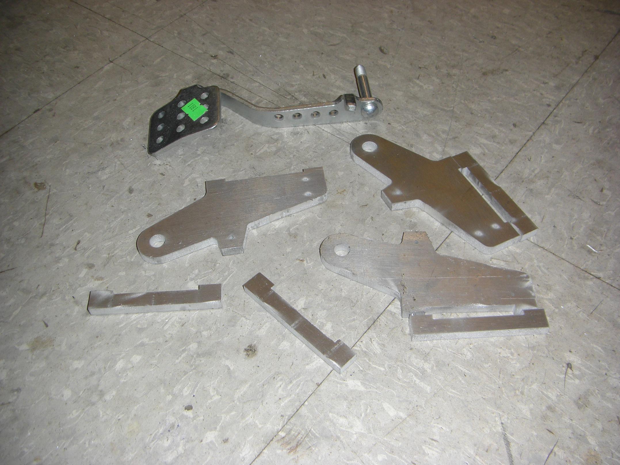
In a rare turn of events, I designed something else for the kart before making it. The other big item that was pre-designed was the back end transaxle assembly. These parts were all waterjet-cut, and obviously one needs a 2D routed path file to run the waterjet machine – I cannot yet sneeze hard enough to cut aluminum, but when I can, rest assured that I’ll make more flat parts on the fly.
I made a few sets of these embryonic pedal mounts. One will become the brake pedal, the other will be turned into the accelerator. They still need things like holes drilled to size and threads tapped.
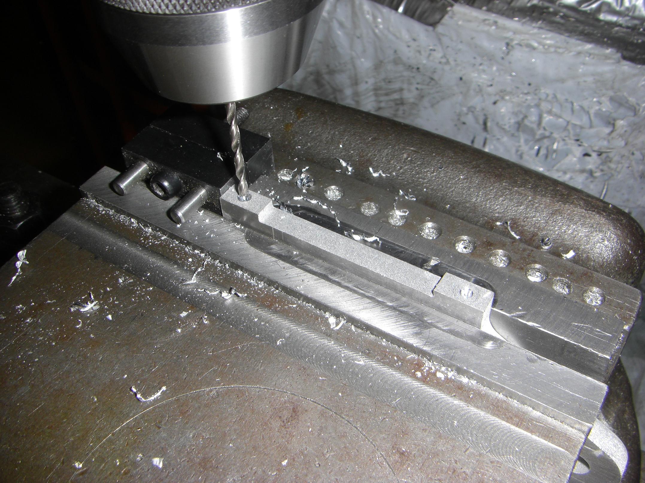
Like so. Drilling 32 holes in the same place on a bilaterally symmetric part was made easy by the mill stop, since I could pop the part in, lock the vise, drill, open the vise, flip around and drop the part back in the other way.
I call this the Pop-Lock-Flip-it-and-Reverse-it technique.
Missy Elliot and Huey could not be reached for comment.
Welcome to another episode of “I hope the kart never actually ends up in this position during operation”. I decided it was easier to roll it onto its backside to install the pedal mounts from underneath, than to fiddle an allen wrench under the thing.
I discovered this after putting in 3 out of 4 screws.
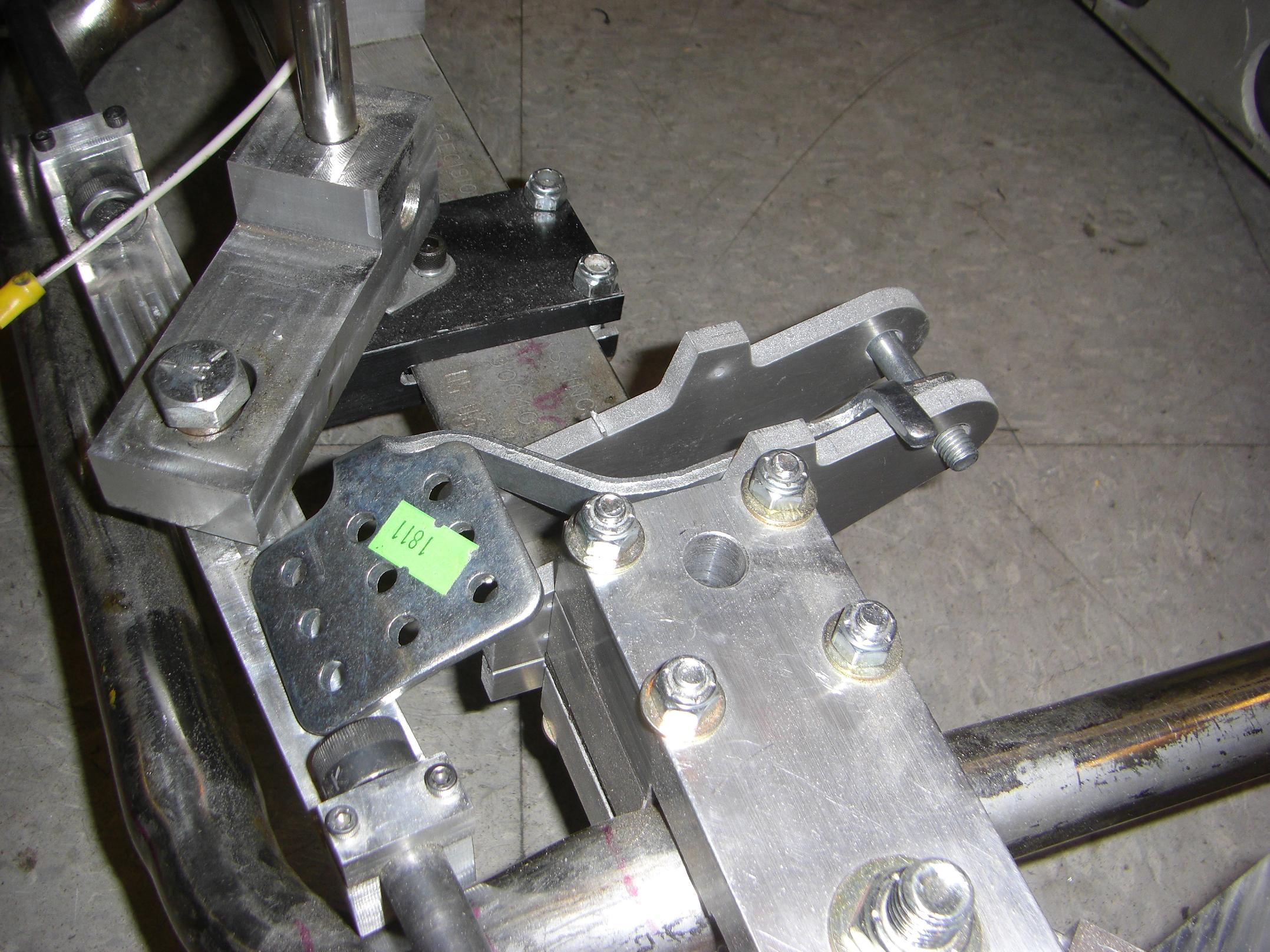
Testing pedal positions. Part of the downside of designing things 5 seconds after you build them is making sure your parts don’t run into eachother. Here, I’m trying various configurations of pedals and mount to ensure that they still clear the steering tie rods. This ended up not being a problem since the pedal could never reach this low – part of the mounts acted as a physical stop when everything was secured.
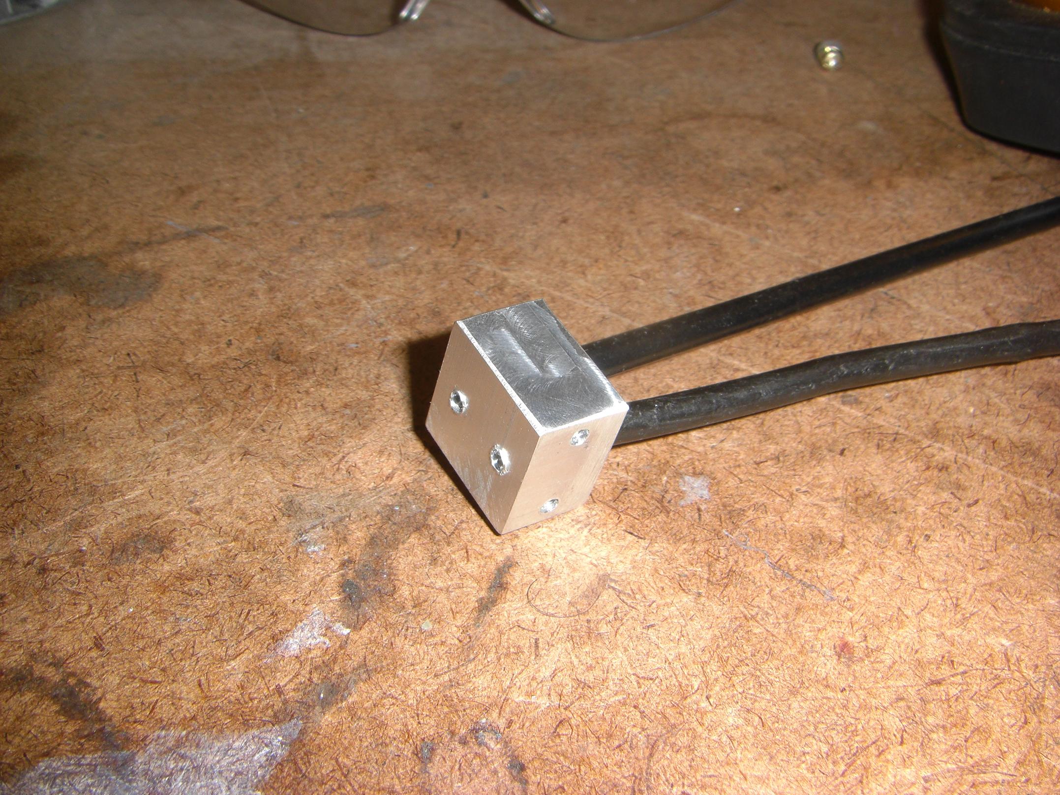
This is the combination cable stop and mount spacing implement. It holds two bike brake cable sheaths securely such that I can route them to the two front wheels.
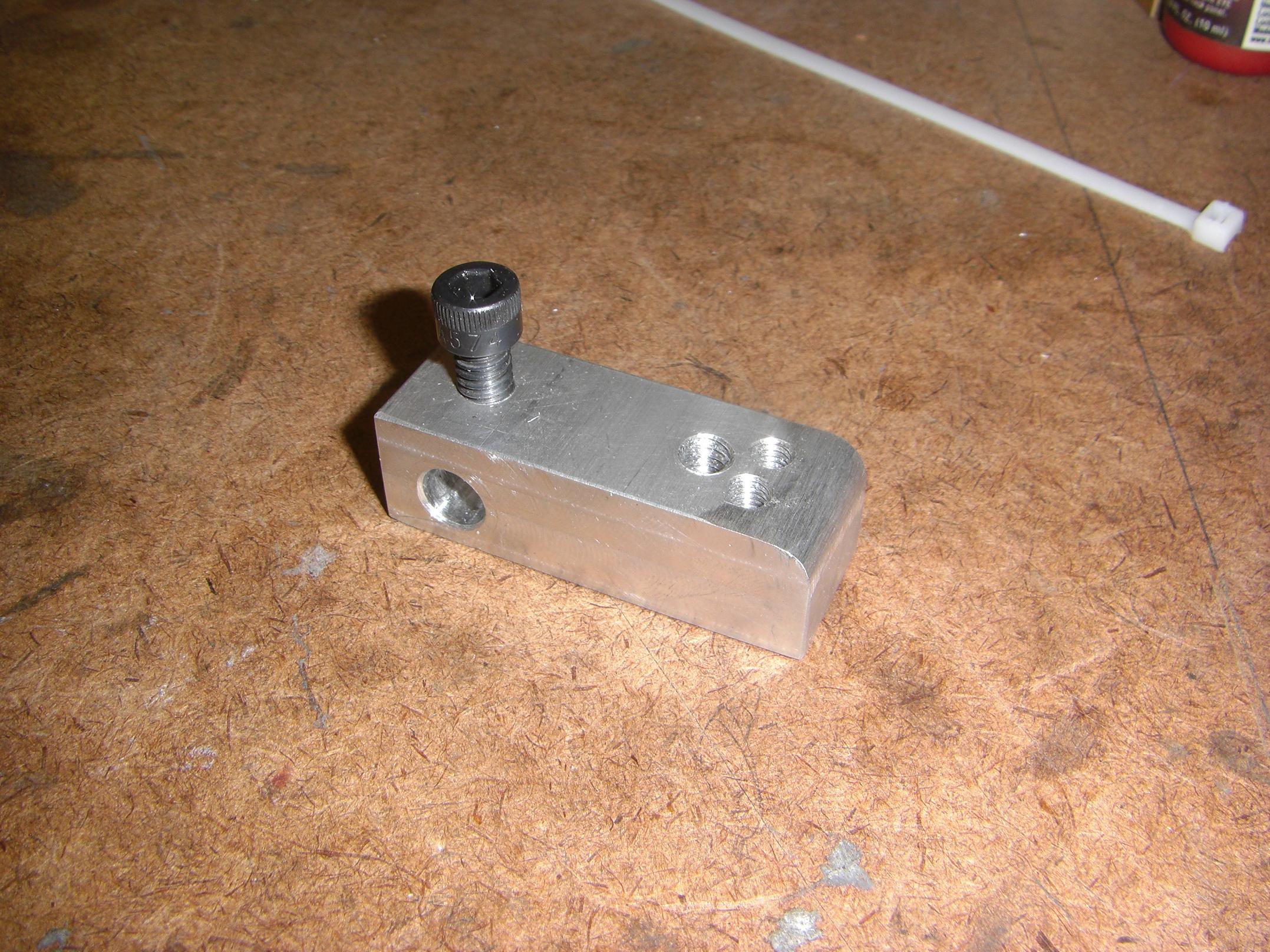
The actual brake lever that will translate my desperate brake stomps into an ineffective tug on the cables. It set-screws onto the pedal’s pivot shaft (Don’t worry, there’s a spot drill just for this!) and has holes on the other end for putting in cable-clamping screws. The end is rounded off to reduce cable stress.
The triangualar screw hole arrangement was the result of “Hmm, let’s make two independent cable clamps… wait, nevermind, let’s make one locking clamp thing for both cables!)
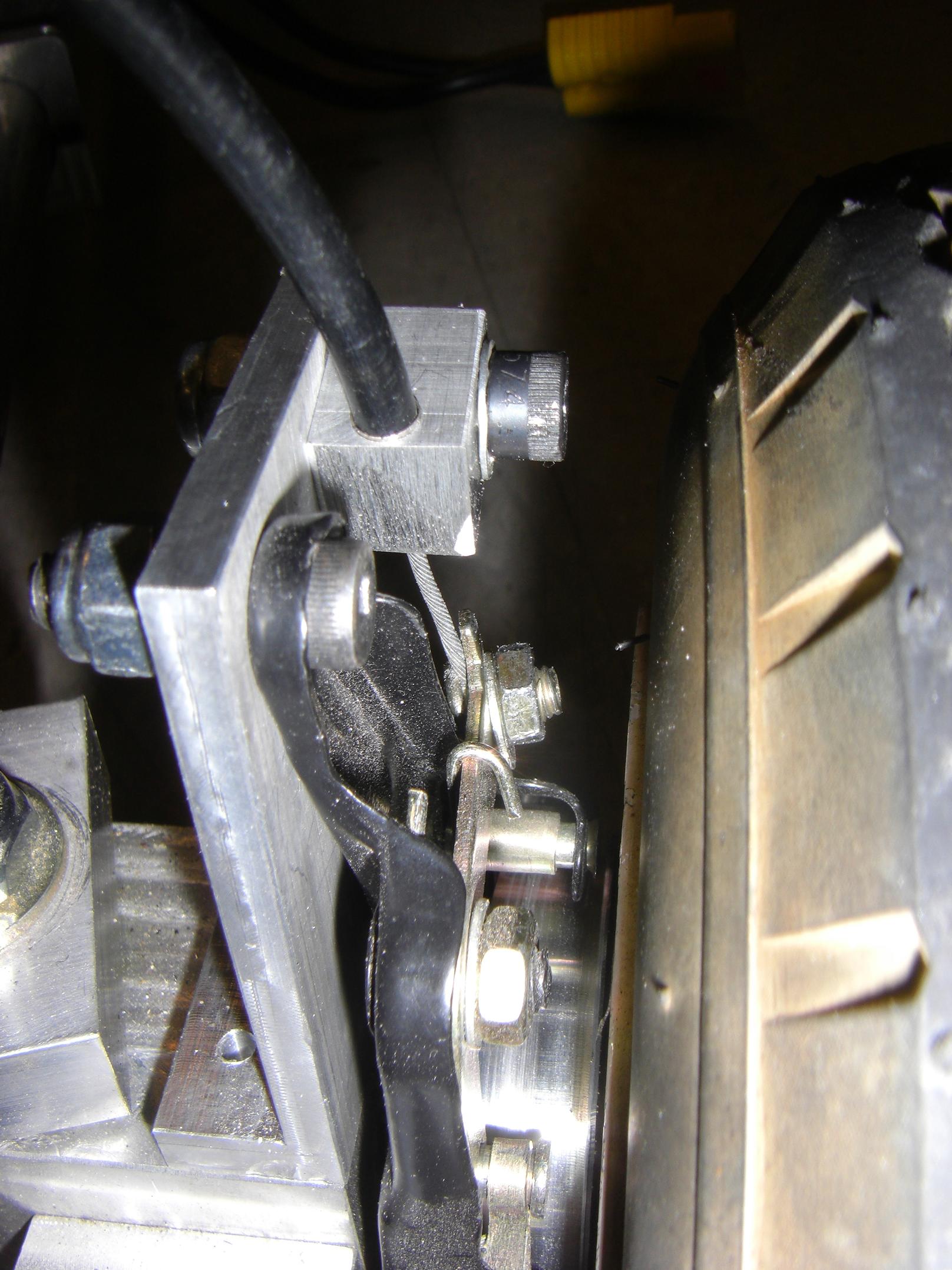
On the other side of the cable are the two band brakes. Conveniently, each had a little clampy screw built into the levers. Here, the Blocks of Cable Sheath Holding (+1?) are also visible.
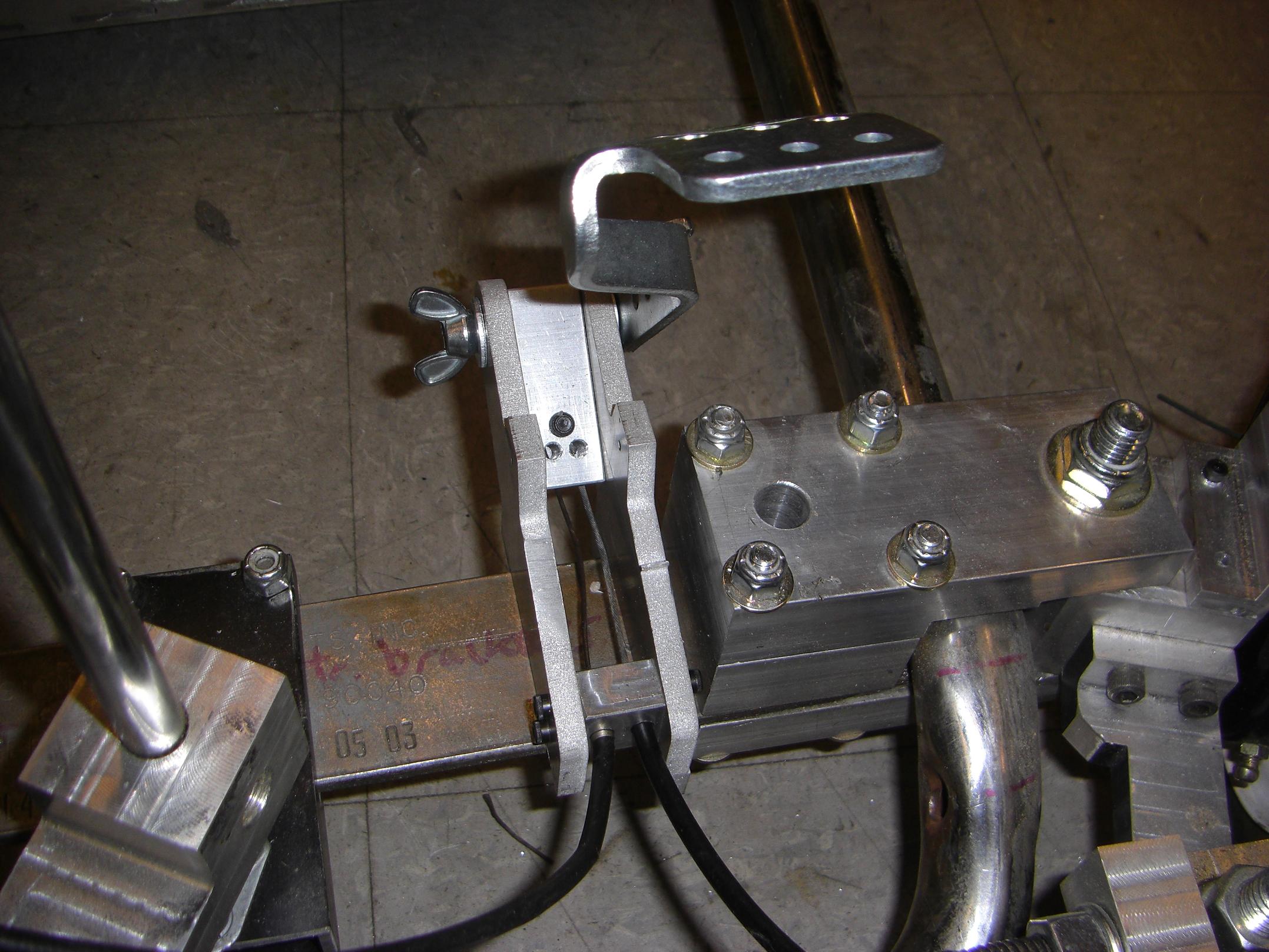
Alright, so everything’s hooked up. The springs on the band brakes transmit sufficient intial tension such that I do not need a return spring on the pedal itself.
Good, because I didn’t think of how I could do that.
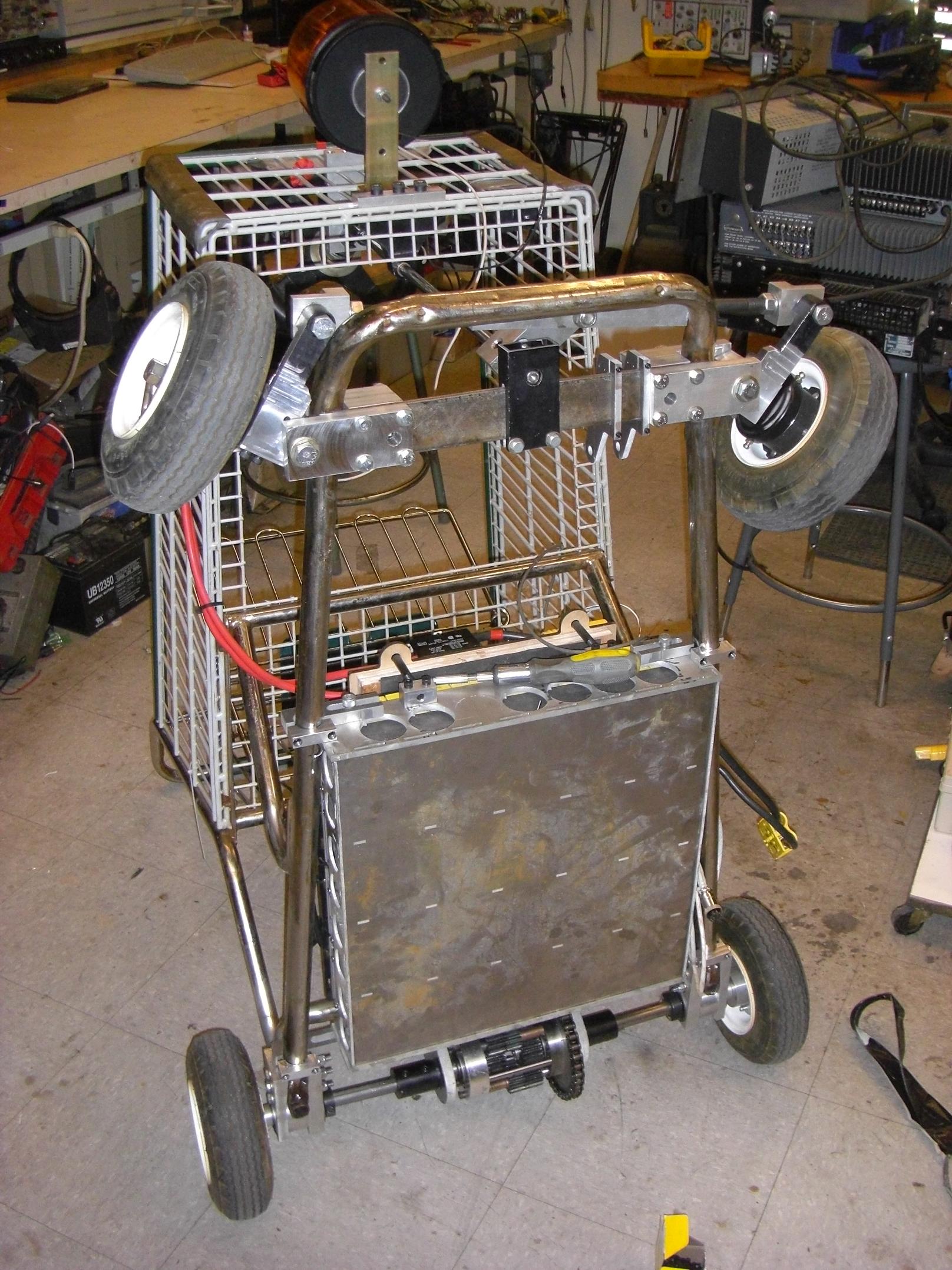
Here it is, LOLrioKart, now with BRAKES! Front brakes! TWO OF THEM! And they WORK!
Well, mostly. It stops well, but pulls hard to the right – this is an unfortunate characteristic of the dinky little scooter band brakes I used. Like some forms of drum brake, band brakes have a preferred direction in which they will “self-servo“, or bite harder with little application of force. For me, this was a forward rotation of the right wheel. Yes, the left front wheel does brake harder if rotating in reverse.
This is why disc brakes are just awesome in general, since the applied force is always at an right angle to the brake pad surface. There’s no motion which would tend to amplify the frictional force. In fact, new designs of disc brake incorporate small cam mechanisms into the cylinders to simulate this self-servo effect.
Regardless, this was one of the design goals of this project, since I haven’t seen many go-karts that have braking on the front wheels. Rear wheel braking is much easier to accomplish, since often the rear axle is solid and driven by a single large (conveniently disc-shaped) sprocket. I decided this was unnecessary, since I already have an electric motor back there which incidentally acts as a fine brake if you squeeze it right.
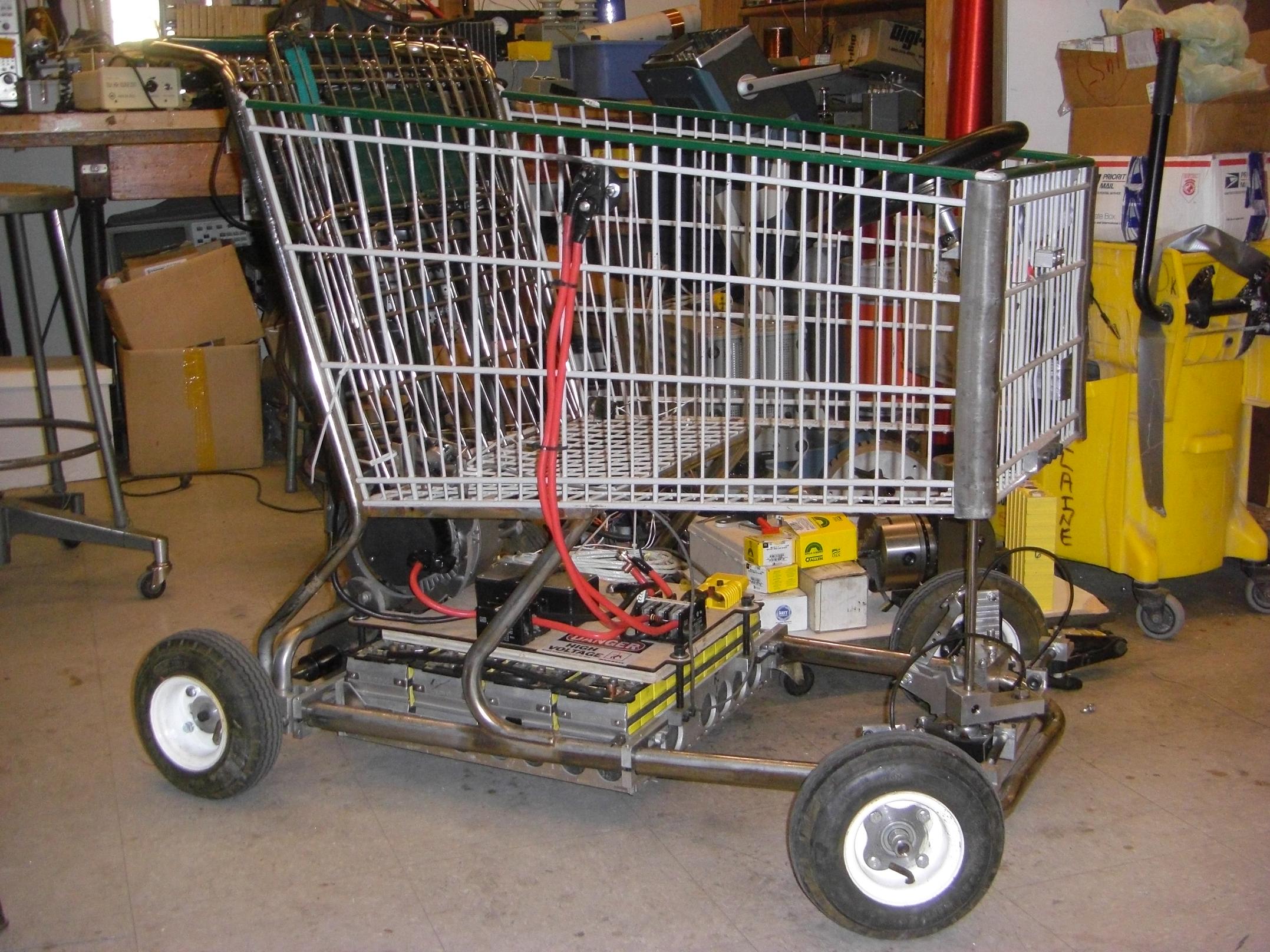
Anyways, it can now stop on command. What does this mean? Epic hoonage to come, especially since if you watch my wiring in the above picture closely – the Etek is wired directly across the Hella key switch.
No, it hasn’t welded closed yet.
Yes, it’s incredible. The kart will actually kick up on the two rear wheels on acceleration, which makes the “nose-in-the-air” picture even more potentially reflective of reality.
No, I never expected my set-screw wheels to survive that kind of torque. Video to come soon, I promise!

Hey, contactors! I grunged an armful of industrial contactors from a free parts pile. They are mostly 24 volt coils, but the 4-pole one is a 120 volt coil. Oddly enough, it still trips extremely well on 54v.
I might consider replacing the giant Hella battery switch with one of these later on, after I put a speed controller between the motor and battery.This would get rid of the enormous red cable leading up to the basket, since the system can be switched using a much smaller, more discrete key switch.
While these are certainly not main battery cutoff contactors, the idea is that they should never be switching the maximum current of the battery, i.e. handling any inrush current, with a proper precharge resistor setup. This high resistance is placed in parallel with the contactor such that a small amount of current can flow as soon as the battery is connected. It fills up any capacitors in the circuit, such as in the controller, which otherwise appear as instantaneous dead shorts on a voltage step (such as suddenly turning your switch on).
This prevents a wall of electrons from getting all arc-y on your semiconductors. I suspect the lack of such a resistor was what killed my previous BLDC controller.
I’d have to split the 4-gauge cables into 3 or 4 smaller (such as 10) gauge ones, which is troublesome, so I might just *get* a real battery cutoff contactor.
Anyways, onto more \m/it \m/echanical \m/ayhem!