Over the past two weeks, I managed to loiter enough around the Media Lab to get some work done on the wheelmotor. All I can say is that it’s “getting there”… those weird things called “classes” get in the way of building things. Who the hell needs ’em?!
 The first step in shoving a motor inside a wheel is to carve the center out of the wheel. This proved to be challenging – polyurethane wheels are squishy and would be nearly impossible to mount on a lathe chuck the conventional way. The spokes also prevent grabbing anything inside the wheel.
 Naturally, I come up with a clever, dangerous, and potentially expensive plan to get around it. The method of attaching the wheel on Snuffles 1 was pressing them onto a circle of pins in a large aluminum pulley.
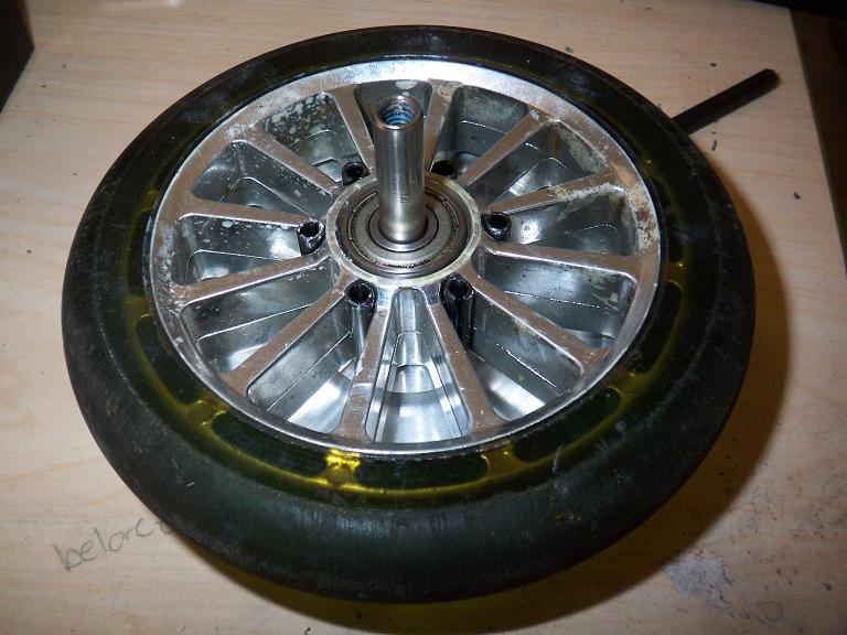
Large aluminum pulley? Perfect! I popped the other wheel off on a press and mounted the new wheel. Then I ran some high speed steel into the plastic spokes at the diameter of the rim, stopping just short of breaking the rim off so I could snap the core out and avoid possibly getting the rim trapped in between big steel spinning things.
 The stator mount designed for the motor is a dished-in piece of aluminum with stubs on it to seat the bearings. However, I decided that it would be much easier to make the dish separate, then press the shaft through. It would involve less wrangling and maneuvering of the tool bit and simplify the process.
The shaft was the first piece I actually made on the lathe (to precision – ripping the spokes out of a plastic wheel isn’t particularly clean). This is a CNC-only lathe that has meta-handles to let you jog the axes. Maximum resolution is .0001 on fine stepping, which was really awesome.
Unfortunately, I can no longer bump the tool into the material to set a zero, because… well, the handles aren’t force-feedback. I had to eyeball tool contact, but could otherwise hold any dimension I wanted down to .0001 +/- the deformation of tool and piece. It turned out well enough for pure eyeballing of the reference zero – .590 was actually .587, but Loctite fills spaces.
After a night’s work, the pieces. I was halfway done with machining the dish part when I realized that I had probably outstayed my welcome – it was almost midnight!
Notice the ring inset into the wheel. This is the “can” part of the motor which will support the magnets.
In order to not have to deal with aligning the finished motor parts on a vise to drill out all 16 perimeter holes 3 separate times, thick aluminum round pieces that have the holes already piloted were cut on a waterjet. That way I could trim them to taste on the lathe. All dimensions on the ring were made .125″ oversize. The two thick blocks under the wheel will eventually become the side plates/bearing mounts, and will be chrome plated for pimpness.
Not.
 Here’s one result of misjudging zeros by a bit. I thought I had lined up with the inner part of the dish, but actually ran the unforgiving Z-axis slightly into the material . Hence zero was a few hundredths off. Nothing life-threatening, but I had to stop and re-eyeball it again. This small part would be better done on a smaller manual machine since it requires smaller tools and more improper machining techniques than the CNC allows.
